
Backlash Identification in Industrial Positioning Systems Aided by a
Mobile Accelerometer Board with Wi-Fi
Mathias Tantau
1 a
, Lars Perner
2
, Mark Wielitzka
1 b
and Tobias Ortmaier
1 c
1
Institute of Mechatronic Systems, Leibniz University Hanover, An der Universit
¨
at 2, 30823 Garbsen, Germany
2
Lenze Automation GmbH, Am Alten Bahnhof 11, D-38122 Braunschweig, Germany
Keywords:
Backlash Identification, Accelerometer, Electric Drives, Electric Power Trains.
Abstract:
In electromechanical motion systems performance measures such as positioning accuracy, dynamic stiffness
and control bandwidth are severely limited by backlash. Several control schemes based on backlash com-
pensation or switching control of hybrid systems are known, but many of these approaches require the exact
backlash width as an input parameter. Several existing approaches for backlash identification are limited in
accuracy because the load-side velocity is required but it is not directly measurable. In this paper a method
for backlash identification tailored to electromechanical motion systems with rotary motor and translationally
moving load is proposed. A mobile sensor board with inertial measurement unit (IMU) is mounted temporar-
ily on the load and serves to acquire the accelerations during the experiment. The connection to the host-PC
is wireless, time synchronisation is not required. It is shown in experiments on a testbed with an adjustable
backlash coupling but otherwise industry-like equipment that high accuracies can be achieved.
1 INTRODUCTION
Electric drives in automation industry are required to
have a high closed-loop bandwidth and a high dy-
namic stiffness in response to external disturbances.
Both is highly limited by backlash between the mo-
tor inertia and the load inertia. Backlash, also called
deadzone, is present in many drive systems, mainly
emerging from gear play.
A number of control metrics have been developed
for systems with backlash (Lagerberg, 2001; Nordin
and Gutman, 2002). Many of them consider the back-
lash gap width explicitly in the design although this
parameter is often unknown and changes over time.
Examples are given in the following paragraph.
An early work on control of systems with back-
lash is the one by Tao and Kokotovic (Tao and Koko-
tovic, 1996). Three different methods of exact lineari-
sation control depending on the availability of angle
sensors at the drive side and/or load side are demon-
strated in (Schoeling and Orlik, 2000). The backlash
width is required in the design. Friedland (Friedland,
1997) developed a load side observer that requires
a
https://orcid.org/0000-0003-1195-7329
b
https://orcid.org/0000-0003-0088-6457
c
https://orcid.org/0000-0003-1644-3685
knowledge of the backlash gap size and the load iner-
tia. A concept based on model predictive control was
developed by Lagerberg and Egardt (Lagerberg and
Egardt, 2005) that requires knowledge of the exact
backlash width. The controller by Nordin and Gut-
man (Nordin and Gutman, 2000) softly switches be-
tween a mode for operation in the backlash gap and
a mode with high gain for operation in contact with
the load. The switching rule requires knowledge of
the backlash width and the stiffness. In (Rostalski
et al., 2007) model predictive control with state ob-
server is proposed for systems with backlash. It is
shown in experiments that uncertainty in the required
model parameters such as the backlash width limits
the performance considerably or respectively leads to
instability. A backlash compensation control scheme
for twin-drive systems with backlash is proposed in
(Itoh, 2008), that requires the backlash width as an
input parameter.
In summary, the explicit consideration of nonlin-
earities like backlash and friction improves perfor-
mance (Marton and Lantos, 2009), but often these
advanced approaches cannot be put into practice be-
cause the required backlash width is not known.
This explains the quest for backlash identification
methods that cannot only detect its presence in the
sense of condition monitoring and fault diagnosis, but
576
Tantau, M., Perner, L., Wielitzka, M. and Ortmaier, T.
Backlash Identification in Industrial Positioning Systems Aided by a Mobile Accelerometer Board with Wi-Fi.
DOI: 10.5220/0009805305760584
In Proceedings of the 17th International Conference on Informatics in Control, Automation and Robotics (ICINCO 2020), pages 576-584
ISBN: 978-989-758-442-8
Copyright
c
2020 by SCITEPRESS – Science and Technology Publications, Lda. All rights reserved

can determine the exact value.
Existing works can mainly be divided into min-
imization of simulation model errors, extraction of
features in the measured signals and online state and
parameter observers. The first group can further be
divided into time domain approaches and frequency
domain approaches. Examples of the former are
the works of (Ravanbod-Shirazi and Besanc¸on-Voda,
2002; Zemke, 2012; Calvini et al., 2015), where back-
lash and other parameters are identified by time do-
main output error minimization with for example par-
ticle swarm as an optimizer. A frequency domain ap-
proach is the one presented by (Popp et al., 2019).
Online observers are addressed in the works of Reddy
(Reddy et al., 2019).
Feature-based methods detect the time instances
when the backlash gap is entered and when it is left.
These are also called commutation times (Ravanbod-
Shirazi and Besanc¸on-Voda, 2002) and mainly show
up in the velocity and current signals of the motor, e.g.
(Gebler and Holtz, 1998). The backlash parameter
is obtained by integrating the velocity difference be-
tween motor and load. Details of the load-side veloc-
ity estimation and the detection of commutation times
depend on the availability of sensors and other system
parameters.
In (Marton and Lantos, 2009) it is utilized that the
load stays at rest after a velocity reversal until the
backlash gap is passed, so in this case the load-side
velocity is known (zero). The re-engagement time
is detected in the motor current. Villwock and Pacas
(Villwock and Pacas, 2009) drive a triangular velocity
and detect the commutation instances right after the
maximum velocity peak by analysing the velocity sig-
nal. The load speed is assumed to be constant. Their
technique can be refined by utilizing also the motor
current signal, especially if the load friction is known
(Han et al., 2016). The load deceleration can also
be determined from the commutation times if a sinu-
soidal excitation is used instead of a triangular one
(Specht, 1986) or if a load-side velocity sensor exists
(Ravanbod-Shirazi and Besanc¸on-Voda, 2002). Two
methods based on the assumption of zero load velo-
city in backlash mode are compared in (Zhang et al.,
2018). One of them detects the contact-separation-
contact times via transmission torque mutations, the
other method measures the load-side speed and uses
a describing function to calculate the backlash angle
from the phase lag of the load’s base frequency.
The limitation of most of these methods is that cer-
tain assumptions about the load are made (constant
load-speed, known friction) which are not satisfied in
all applications and the true behaviour of the load is
not known if no load-side sensor exists. In real-life
applications it is expectable that the friction is not
negligible and it is not measurable independent of the
motor friction. Gravity is another problem. Load-side
sensors could be installed but only at high costs and
cabling efforts.
This paper aims at backlash identification for ro-
tary motors by the help of a mobile, radio controlled
sensor board based on an inertial measurement unit
(IMU). It is attached temporarily to the linearly mov-
ing load and helps to reconstruct the load-side veloc-
ity. The main goal of the presented technique of this
paper is to improve the identification accuracy based
on these extra data. Installation effort is minimized
because the sensor board transmits the measurements
via Wi-Fi and it is battery-powered.
2 BACKLASH IDENTIFICATION
This section describes the proposed procedure of
backlash identification for an electrical power train
with belt drive as shown in Fig. 1. A controlled servo
motor with angle or angular velocity sensor is con-
nected to a translationally guided load by means of a
belt drive, toothed rack and pinion, or a ball screw.
In the figure a revolving belt drive is shown. Often,
there is also a gearbox with backlash behind the mo-
tor. The gear ratio is i, the backlash angle is 2α and
the feed constant of the translational element is c
f
, e.g.
c
f
= 2πR for the belt drive with pulley radius R. Such
a configuration is encountered frequently in automa-
tion industry, for example in linear positioning sys-
tems, stacker cranes, rapid prototyping and machine
tools. In contrast to testbeds with free-wheeling load
the belt drive has considerable friction, but as an ad-
vantage the linear acceleration of the load a(t) can be
used as an additional input signal for backlash identi-
fication.
Servo
drive
Motor with
sensor
Gearbox with
backlash
Translation into
linear motion
Load
Figure 1: Drive train of electromechanical positioning sys-
tem with rotary motor and linearly moving load.
The proposed procedure is developed along Fig. 2.
Although the exact experimental setup is postponed
till Sec. 3 this measurement for 10
◦
serves already
now as a demonstration. It is assumed for now that
gravity has no influence, i.e. the linear motion is hori-
zontal. Similar to the approach of Villwock (Villwock
and Pacas, 2009) the motor is commanded to acceler-
Backlash Identification in Industrial Positioning Systems Aided by a Mobile Accelerometer Board with Wi-Fi
577
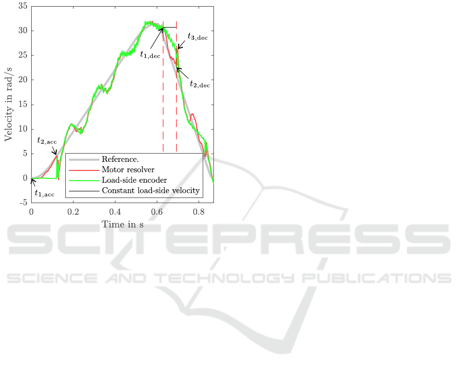
ate up to a certain maximum velocity, followed by a
sharp deceleration, as indicated in grey, Ω
ref
(t). In red
the actual motor speed is shown. In addition, the ve-
locity of the load-side of the backlash element is given
(green line). This signal is measured for visualization
only and it is not used for backlash identification.
Figure 2: Velocities of an exemplary experiment with 10
◦
backlash setting without acceleration sensor.
Due to our long-term goal of using the identi-
fied backlash for control design, all measurements are
done with misadjusted control parameters. This leads
to clearly observable oscillations after each backlash
impact. The identification algorithm is robust enough
to handle this suboptimal system behaviour.
There are two distinct patterns where the backlash
becomes evident. In the beginning of the acceleration
phase the load remains at rest while the motor accel-
erates already and traverses the backlash gap. This
effect is utilized in (Marton and Lantos, 2009). When
the impact with the load-side occurs, the motor ve-
locity drops instantaneously to a value close to zero
while simultaneously the load is accelerated. The sec-
ond characteristic pattern is observed after the veloc-
ity peak has been passed in the deceleration phase. It
can be seen that the motor decelerates faster than the
load and a clear divergence between the two veloci-
ties occurs. At the other end of the backlash gap the
motor re-engages with the load and is accelerated by
the impact force. This effect is utilized in (Villwock
and Pacas, 2009).
For backlash identification both patterns (acceler-
ation and deceleration) can be evaluated as long as the
commutation times can safely be recognized and the
load-side velocity can be approximated (Villwock and
Pacas, 2009):
2α =
Z
t
2
t
1
Ω
M
(t) −Ω
L
(t)dt
. (1)
Ω
M
and Ω
L
are the angular velocity of motor and
load, respectively. t
1
and t
2
are the commutation times
before and after backlash gap passing. They are re-
placed by the times with index acc and dec for ac-
celeration and deceleration phase, respectively, see
Fig. 2.
For fully automatic backlash identification, con-
ditions for detecting the commutation times must be
established. In the acceleration phase t
1,acc
coincides
with t = 0. It is ensured by a slow backward move-
ment preceding the experiment that the backlash el-
ement is actually at the one end, in a defined state
when the shown velocity profile begins. t
2,acc
can be
detected by a sharp drop in the motor velocity. Here,
t
2,acc
is defined as the time instant in the acceleration
phase when the maximum motor velocity is reached
which is followed by a drop in the velocity of at least
50% of this maximum.
50% is the value expectable for bounce-free but
undamped re-engagement by conservation of momen-
tum if the inertia ratio of motor and load is 1. Usually,
the load inertia exceeds the motor inertia, leading to a
deeper drop and 50 % is a safe setting. On the other
hand, if the load is lighter, backlash identification be-
comes less important for control design, because the
control parameters are predominantly determined by
the motor inertia.
In the deceleration phase t
1,dec
is defined as the
time instant corresponding to the maximal motor ve-
locity after the maximum in the reference speed has
been reached (first dashed line in Fig. 2). t
2,dec
is
more difficult to determine automatically. First, the
maximum in Ω
M
(t) −Ω
ref
(t) is found and marked as
t
3,dec
. Then, the minimum in the motor velocity be-
tween t
1,dec
and t
3,dec
is detected and associated with
t
2,dec
(second dashed line). Typically, t
2,dec
and t
3,dec
are close together.
Approximating the load-side velocity in the time
interval of interest in the acceleration phase is trivial
because without gravity the load should be at rest, so
the velocity is zero (Marton and Lantos, 2009). For
the deceleration phase it can be assumed that the load
velocity is constant and identical to Ω
M
(t
1,dec
) (black
line). While Villwock (Villwock and Pacas, 2009)
achieved good results with this approximation, it was
found that in a real setting with friction in the driven
mechanics a large error is introduced. In Fig. 2 this
error can be quantified by comparing the surface areas
between the green and black line, resp. between the
ICINCO 2020 - 17th International Conference on Informatics in Control, Automation and Robotics
578
red and green line in the time interval marked by the
dashed lines.
Now, the accelerometer comes into the picture.
It is mounted on the translationally moving load and
measures accelerations in three axes. The component
in the direction of motion a(t) serves to obtain the
velocity between the dashed lines from numeric inte-
gration of discrete-time signals:
ˆ
Ω
L,k+1
=
ˆ
Ω
L,k
+ 2πia
k
T
s
/c
f
. (2)
In this equation ˆ stands for the estimate and T
s
for the
sampling time. The time at sampling instant k, kT
s
is
shortened by the index k.
At kT
s
= t
1,dec
the velocity could be initialized
to the current motor measurement, but since this
would depend on one single, noisy measurement a
better alternative is to utilize also the common move-
ment of motor and load during the acceleration phase.
The sensor fusion of motor position measurement
and accelerometer measurement could be realized via
Kalman filtering (Shim et al., 1998), or since the cal-
culation is performed offline Kalman smoothing is
also possible (S
¨
arkk
¨
a, 2013). Here, the acceleration
is simply integrated and the known motor velocity is
used as a feedback:
ˆ
Ω
L,k+1
= (1 −ε)
ˆ
Ω
L,k
+ 2πia
k
T
s
/c
f
+ εΩ
M,k
. (3)
ε is a tuning factor that is adapted manually to adjust
the dynamics of the estimate.
Since the accelerometer outputs the data with a
certain, a priori unknown offset a:
a
raw,k
= a
k
+ a, (4)
this offset must be determined and compensated. We
can utilize the fact that right before and after the ex-
periment the velocity is known to be equal and zero:
ˆ
Ω
LN
=
ˆ
Ω
L0
+
2πiT
s
c
f
[a
0
+ a
1
+ ···+ a
N−1
+ Na].
(5)
With
ˆ
Ω
LN
=
ˆ
Ω
L0
= 0 (5) can be solved for a, which
is then subtracted from a
raw
.
Another essential preparation step is the synchro-
nisation of signals in time. Since the mobile sensor
for acceleration measurement is started remotely via
a non-realtime connection, the acceleration may have
a time shift. For time synchronisation the cross corre-
lation between the acceleration signals from the two
sensors (motor and accelerometer) is maximized:
lag = arg max
m
k=∞
∑
k=−∞
2πia
k+m
c
f
Ω
M,k+1
−Ω
M,k
T
s
. (6)
This way the time lag is determined and the first lag
samples of a
k
are discarded before the above calcula-
tions are carried out.
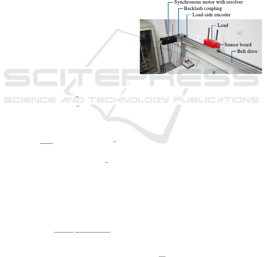
3 EXERIMENTAL SETUP
For the experimental validation the testbed shown in
Fig. 3 is used. A synchronous motor of the type MCS
12L20 with a rated power of 2.8 kW and a rated torque
of 13.5 Nm is driven by an 9400 servo inverter, both
from Lenze. It is connected to a belt drive of 2.20 m
length by a coupling with adjustable backlash. The
load allows for weight adjustment, but in these ex-
periments a constant load of 11 kg is chosen. On the
load-side of the backlash coupling a rotary multiturn
encoder ’ATD 2B A 4 Y26’ from Baumer Thalheim is
mounted. The resolution of the encoder is 17bits/rev.
Servo inverter and encoder are connected to the main
controller, ’3200 C’ from Lenze via EtherCAT.
Figure 3: Experimental setup.
Figure 4 shows the backlash coupling, which
works similar to the one described in (Villwock,
2007). Ball bearings have been integrated to facili-
tate the alignment. The gap width can be adjusted in
steps: 0
◦
,0.5
◦
,··· ,4.5
◦
,5
◦
,6
◦
,··· ,20
◦
. This range of
adjustable values is comparable to other couplings or
gearboxes with adjustable deadzone (Dagalakis and
Myers, 1985; Schoeling and Orlik, 2000; Merzouki
et al., 2006; Rostalski et al., 2007). In (Merzouki
et al., 2006) the deadzone can even be extended up
to 24
◦
. Industrial gearboxes have a motor-side back-
lash angle in a similar range, typically more for high
transmission ratios (Lenze, 2020).
The mobile sensor is attached to the load with
an ordinary tape. Figure 5 shows a detailed view of
the sensor board. It is based on an Arduino ESP32
NodeMCU from Espressif with dual-core controller
running at 80 MHz and 802.11 b/g/n Wi-Fi function-
ality. The lower PCB has been added to integrate
three SRAM devices ’IS62WVS2568FBLL-20NLI’
with 2 Mb,20 MHz as a data buffer. Also, the MEMS
(micro-electromechanical systems) IMU ’LSM6DS3’
is mounted on the lower PCB. It is configured to mea-
sure accelerations in three axes with a resolution of
16Bits at ±2g full range, at a nominal noise level of
90µg/
√
Hz.
Backlash Identification in Industrial Positioning Systems Aided by a Mobile Accelerometer Board with Wi-Fi
579
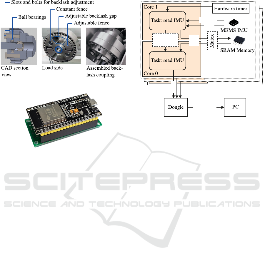
Figure 4: Coupling with adjustable backlash.
Figure 5: Sensor board with MEMS IMU and Wi-Fi data
transmission.
In Fig. 6 the principle of data transmission is
shown. Real-time operating system FreeRTOS
TM
(Amazon Web Services, Inc., 2020) is running on
the sensor board with two tasks, one for reading the
measurements from the IMU and storing them in the
SRAM devices and one for transmitting the data via
Wi-Fi to the receiver. Reading the accelerations from
the sensor can be synchronized with the clock of the
actual measurement, which can be set in steps up
to 1.66 kHz. In this case it is initiated by an inter-
rupt from the sensor. Alternatively, an arbitrary sam-
pling rate can be realized by a hardware timer inter-
rupt. It was found that tolerances of the sensor sam-
pling rate lead to problems in time synchronisation.
For that reason the sensor is configured to measure at
1.66kHz, while the data are recorded asynchronously
at 1 kHz. This leads to time jitter, but aliasing is pre-
vented by a low-pass filter at 400 Hz inside the IMU.
Data are transmitted to a receiver board via Wi-Fi
Direct mode, which allows the simultaneous connec-
tion of several sensor boards without a wireless router.
The receiver is also an ESP32, which is connected to
the computer over USB.
4 EXPERIMENTAL RESULTS
In this section experimental results are reported for
backlash identification. Firstly, in deceleration phase
Receiver board 3
Receiver board 2
USB/Serial
vSPI
Interrupt
Wi-Fi
hSPI
hSPI
Receiver board 1
Counting
Semaphore
Figure 6: Schematic of the data transmission from the mo-
bile sensor boards to the PC.
without accelerometer, secondly in acceleration phase
with zero load velocity and thirdly, in deceleration
phase with the mobile sensor unit.
For the identification in deceleration phase with-
out accelerometer identified backlash angles are
shown against those that have been configured in the
backlash coupling in Fig. 7. Measurements have been
repeated for five motor orientations spread equally
over one rotation. This procedure ensures that the
identification works not only for one particular ori-
entation. In addition, as a reference the backlash val-
ues have been measured by the help of the load-side
encoder (black line). For this experiment the motor-
side part of the backlash coupling was fixed and the
load-side position was rotated slowly by hand, while
the minimum and maximum encoder readings were
recorded.
The fact that the reference measurement is almost
an identity line confirms that the backlash coupling
has been machined accurately, although the actual
width is always approximately 0.5
◦
too low. The
identification result is far above the correct value, for
most widths even exceeding 200%. This can be ex-
plained by the error due to neglecting the deceleration
of the load as already shown in Fig. 2.
The result for the acceleration phase is shown in
Fig. 8. These experiments reveal a high accuracy
and repeatability which suggests a clear superiority
of the method. However, it is less robust to sources of
disturbing torques not considered explicitly. For ex-
ample, position-dependent friction could lead to sim-
ilar drops in the velocity causing confusion with the
backlash-induced effect. Also, if due to a slight in-
clination of the linear drive there is a small gravity
ICINCO 2020 - 17th International Conference on Informatics in Control, Automation and Robotics
580
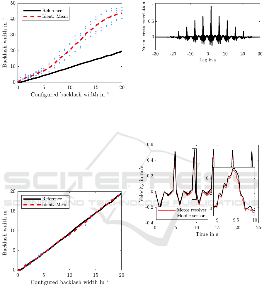
Figure 7: Identified vs. configured backlash width when the
load velocity is assumed to be constant and the backlash is
identified in the deceleration phase.
torque, the load acceleration will depart from zero
during the measurement or the load might leave the
one end of the backlash gap prior to the measurement.
It is expectable that it could even become impossible
to detect t
2,acc
. So, although the results in the acceler-
ation phase are good, it is expectable that this method
is not robust and suffers from similar problems as the
methods cited above that make certain assumptions
about the load-speed.
Figure 8: Identified vs. configured backlash width when the
load velocity is assumed to be constant and the backlash is
identified in the acceleration phase.
In the following, the results with accelerometer
are reported. For an angle of 10
◦
the results of the
time synchronisation step are shown in Fig. 9. In this
figure as well as in all other experiments a clear max-
imum can be seen and time synchronisation is readily
possible.
After time synchronisation and drift elimination
the velocity could be obtained from the accelerome-
Figure 9: Cross correlation between accelerometer mea-
surement a(t) and numerically differentiated motor velocity
Ω
M
(t).
ter with only a minor error as shown in Fig 10. Al-
though only the velocities before and after the five
movements are used for calibration, both graphs are
in good agreement. But this free integration result is
not actually needed and only shown as a verification.
Instead the velocity is estimated as explained above
with the result given in Fig. 11.
Figure 10: Velocity obtained from motor encoder
Ω
M
(t),resp. by integration from the mobile accelerometer.
For the same 10
◦
recording as in Figs. 9 and 10
the velocities of the three different sources are shown.
ε is set to 5%. Apparently, the accelerometer is in
good agreement with the encoder in the deceleration
phase while the backlash gap is traversed.
This impression is confirmed by the other experi-
ments, see Fig. 12. Backlash identification is possible
with low variance and high repeatability, albeit less
good than in the acceleration phase, compare Fig. 8.
Some of the results for 1.5
◦
or less are erroneous be-
cause the time t
2
could not be extracted safely, possi-
bly because the effect of the impact is less pronounced
for small backlash widths. This can be observed in
Fig. 7, too.
Backlash Identification in Industrial Positioning Systems Aided by a Mobile Accelerometer Board with Wi-Fi
581
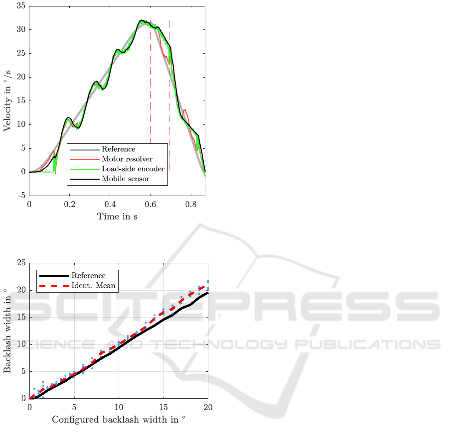
Figure 11: Velocities of an exemplary experiment with 10
◦
backlash setting with acceleration sensor.
Figure 12: Identified vs. configured backlash width when
the load velocity is obtained from the accelerometer, decel-
eration phase.
5 DISCUSSION
The presented approach towards backlash identifica-
tion was shown to provide a high accuracy, especially
for high backlash angles. This is remarkable as the ef-
fort and cost of installing the temporary sensor board
at the load is small and it is not necessary to synchro-
nize the different sensors in time. Apparently, the belt
elasticity does not impair the measurements signifi-
cantly. Many applications as listed above could bene-
fit from such a mobile sensor for backlash identifica-
tion. Although not confirmed experimentally, it can
be expected that small disturbances, such as gravity
should not impair the identification significantly, be-
cause they are detected by the IMU.
Only in the low backlash domain of 1.5
◦
or less
the commutation times could not always be detected
correctly leading to scattering of the results. Fur-
thermore, the experiments have shown that machin-
ing inaccuracies in the backlash coupling lead to an-
gle dependencies and tolerances in the range of 0.5
◦
.
Therefore, the validation of the methods is also lim-
ited in accuracy and scattering of the measurements
can partly be attributed to machining, not to the iden-
tification method. The results could be improved by
averaging several measurements, which was not taken
into account here.
It is astonishing how (Marton and Lantos, 2009)
could achieve identification tolerances of only a few
percent for backlash angles of 0.47
◦
, resp. 0.35
◦
. In
(Han et al., 2016), too, accuracies of a few percent are
achieved for 1
◦
. A possible explanation might be the
idealized setup in their experiments contrasting with
the more industry-like setup of our testbed.
It remains to be investigated if the results are
equally good for a real gearbox instead of the back-
lash coupling. Possibly, oil between the teeth and the
interplay of the multiple gear ranges could hinder a
clear detection of the commutation times. Also, if the
transmission ratio is high and accordingly the load ve-
locity is slow, it could become increasingly difficult to
reconstruct the load velocity from the accelerometer
measurement.
Future works should investigate the applicability
of MEMS gyroscopes for purely rotary settings. With
a sensor board like the one used in this work it is pos-
sible to capture also rotating parts with little effort.
6 CONCLUSIONS
In this paper a method for backlash identification in
electric drive trains has been proposed. It is tailored
to electromechanical motion systems with rotary mo-
tor and translationally moving load. A mobile sensor
board with IMU is mounted temporarily on the load
and transmits the measured accelerations via Wi-Fi,
thus requiring no cabling. Is was shown in experi-
ments with an adjustable backlash coupling that high
accuracies can be achieved even if the load-side fric-
tion and inertia are unknown, which has so far been a
challenge with series sensor equipment. The testbed
used for the experiments consists of industrial equip-
ment, except for the coupling with adjustable back-
lash. It must still be investigated if similar results
can be achieved with a gearbox instead of the back-
ICINCO 2020 - 17th International Conference on Informatics in Control, Automation and Robotics
582

lash coupling. The IMU measurement can be initiated
manually independent of the hardware that controls
the motor, because time synchronisation is possible
based on the recorded signals.
ACKNOWLEDGEMENTS
This work was sponsored by the AiF (Arbeits-
gemeinschaft industrieller Forschungsvereinigungen
Otto von Guericke e.V.) and managed by the FVA
(Forschungsvereinigung Antriebstechnik e.V.) both in
Germany.
REFERENCES
Amazon Web Services, Inc. (2020). FreeRTOS
TM
- real-time operating system for microcontrollers.
https://www.freertos.org/index.html, accesssed: Feb.
2020.
Calvini, M., Carpita, M., Formentini, A., and Marchesoni,
M. (2015). Pso-based self-commissioning of electrical
motor drives. IEEE Transactions on Industrial Elec-
tronics, 62(2):768–776.
Dagalakis, N. G. and Myers, D. R. (1985). Adjustment
of robot joint gear backlash using the robot joint test
excitation technique. The international journal of
robotics research, 4(2):65–79.
Friedland, B. (1997). Feedback control of systems with par-
asitic effects. In Proceedings of the 1997 American
Control Conference (Cat. No. 97CH36041), volume 2,
pages 937–941. IEEE.
Gebler, D. and Holtz, J. (1998). Identification and compen-
sation of gear backlash without output position sensor
in high-precision servo systems. In IECON’98. Pro-
ceedings of the 24th Annual Conference of the IEEE
Industrial Electronics Society (Cat. No. 98CH36200),
volume 2, pages 662–666. IEEE.
Han, Y., Liu, C., and Wu, J. (2016). Backlash identifica-
tion for PMSM servo system based on relay feedback.
Nonlinear Dynamics, 84(4):2363–2375.
Itoh, M. (2008). Torsional vibration suppression of a twin-
drive geared system using model-based control. In
2008 10th IEEE International Workshop on Advanced
Motion Control, pages 176–181. IEEE.
Lagerberg, A. (2001). A literature survey on control of au-
tomotive powertrains with backlash. Technical Re-
port R013/2001, Control and Automation Laboratory,
Chalmers University of Technology, G
¨
oteborg, Swe-
den.
Lagerberg, A. and Egardt, B. (2005). Model predictive con-
trol of automotive powertrains with backlash. IFAC
Proceedings Volumes, 38(1):1–6.
Lenze (2020). Product-related documentation. https://
www.lenze.com/en-de/services/knowledge-base/
product-related-documentation/, accesssed: Feb.
2020.
Marton, L. and Lantos, B. (2009). Friction and backlash
measurement and identification method for robotic
arms. In 2009 International Conference on Advanced
Robotics, pages 1–6. IEEE.
Merzouki, R., Davila, J. A., Cadiou, J. C., and Fridman, L.
(2006). Backlash phenomenon observation and identi-
fication. In 2006 American Control Conference, pages
3322–3327. IEEE.
Nordin, M. and Gutman, P.-O. (2000). Nonlinear speed con-
trol of elastic systems with backlash. In Proceedings
of the 39th IEEE Conference on Decision and Control
(Cat. No. 00CH37187), volume 4, pages 4060–4065.
IEEE.
Nordin, M. and Gutman, P.-O. (2002). Controlling mechan-
ical systems with backlash – a survey. Automatica,
38(10):1633–1649.
Popp, E., Tantau, M., Wielitzka, M., Ortmaier, T., and
Giebert, D. (2019). Frequency domain identification
and identifiability analysis of a nonlinear vehicle driv-
etrain model. In 2019 18th European Control Confer-
ence (ECC), pages 237–242. IEEE.
Ravanbod-Shirazi, L. and Besanc¸on-Voda, A. (2002).
Backlash identification: a two step approach. IFAC
Proceedings Volumes, 35(1):85–90.
Reddy, P., Darokar, K., Robinette, D., Shahbakhti, M.,
Blough, J., Ravichandran, M., Farmer, M., and Doer-
ing, J. (2019). Control-oriented modeling of a vehicle
drivetrain for shuffle and clunk mitigation. Technical
report, SAE Technical Paper.
Rostalski, P., Besselmann, T., Bari
´
c, M., Belzen, F. V.,
and Morari, M. (2007). A hybrid approach to mod-
elling, control and state estimation of mechanical sys-
tems with backlash. International Journal of Control,
80(11):1729–1740.
S
¨
arkk
¨
a, S. (2013). Bayesian filtering and smoothing, vol-
ume 3. Cambridge University Press.
Schoeling, I. and Orlik, B. (2000). Control of a nonlinear
two-mass system with uncertain parameters and un-
known states. In IEEE Industry Applications Confer-
ence (Cat. No. 00CH37129), volume 2, pages 1096–
1103. IEEE.
Shim, H., Kochem, M., and Tomizuka, M. (1998). Use of
accelerometer for precision motion control of linear
motor driven positioning system. In IECON’98. Pro-
ceedings of the 24th Annual Conference of the IEEE
Industrial Electronics Society (Cat. No. 98CH36200),
volume 4, pages 2409–2414. IEEE.
Specht, R. (1986). Ermittlung von Getriebelose und
Getriebereibung bei Robotergelenken mit Gleich-
stromantrieben. VDI-Berichte, (598):71–83.
Tao, G. and Kokotovic, P. V. (1996). Adaptive control of
systems with actuator and sensor nonlinearities. John
Wiley & Sons, Inc.
Villwock, S. (2007). Identifikationsmethoden f
¨
ur
die automatisierte Inbetriebnahme und Zu-
stands
¨
uberwachung elektrischer Antriebe. PhD
thesis, Universit
¨
at Siegen.
Villwock, S. and Pacas, M. (2009). Time-domain iden-
tification method for detecting mechanical backlash
Backlash Identification in Industrial Positioning Systems Aided by a Mobile Accelerometer Board with Wi-Fi
583

in electrical drives. IEEE Transactions on Industrial
Electronics, 56(2):568–573.
Zemke, S. (2012). Analyse und modellbasierte Regelung
von Ruckelschwingungen im Antriebsstrang von
Kraftfahrzeugen. PhD thesis, Leibniz Universit
¨
at
Hannover.
Zhang, J., Zhang, H., and Xiao, X. (2018). New iden-
tification method for backlash of gear transmission
systems. In 2nd IEEE Advanced Information Man-
agement, Communicates, Electronic and Automation
Control Conference (IMCEC), pages 378–382. IEEE.
ICINCO 2020 - 17th International Conference on Informatics in Control, Automation and Robotics
584
