
Experimental Theoretical Study of the Mobile Robotic System
Movement with Caterpillar-modular Propulsion on the Beach Line
Terrain
Alexander Belyaev
1
, Alexey Papunin
1
, Evgeny Zharkov
2
, Alexey Vasiliev
1
, Vladimir Belyakov
1
and Vladimir Makarov
1a
1
Nizhny Novgorod State Technical University n.a. R.E. Alekseev, Minin St., 24, Nizhny Novgorod, Russian Federation
2
GAZ Group's United Engineering Center, Nizhny Novgorod, Russian Federation
Keywords: AMRC, Modeling, Caterpillar-modular Propulsion, Beach Line Terrain, Adams, ATV, Unmanned Ground
Vehicles.
Abstract: This article presents the data for mobile robotic system motion modeling with caterpillar-modular
propulsion on the sand support base. The study provides the basics of the development of the calculation
model in Adams Tracked Vehicle amid mass and geometric chassis parameters and characteristics of non-
rigid soil. The study presents the 3D views of the model created. The study provides the fragments of
curvilinear motion. The study provides graphs of behavior moments for chassis beads, as well as shows the
total resistance to motion on sandy beach. The mean of the moment on one bead during linear motion
amounted to 172 Nm, during curvilinear 195 and 217 Nm respectively for backward and overleaping
chassis beads. The mean resistance to motion during linear motion amounted to 1606 N, during curvilinear
to 1943 N. To validate the results of the modeling we have conducted experimental studies.
1 INTRODUCTION
The monitoring of beach line terrain can be done
with the help of fixed stations, research equipment
can be installed on a special mobile robotic system
(Barber and Mills 2007, Belyakov et al. 2017, Bio et
al. 2015, Didier et el. 2015, Incoul et al. 2014,
Kramer and Hunter 2007, Kurkin et al. 2015, 2017,
Serra et al. 2005, Wübbold et al. 2009, Zaytsev at. al
2017).
To solve the issue of providing movement for
mobile robotic systems, it is necessary to choose
chassis with the most suitable parameters for
operating conditions, as well as for the requirements
of the attached list of active jobs.
Depending on the issues needed we can use a
different mathematical apparatus for modeling
motion and interaction of propulsions with the
surface lane. One of the ways is the imitational
modeling using the MSC.ADAMS program.
However, a test on the real-life object is needed to
a
https://orcid.org/0000-0002-4423-5042
confirm calculations. This object is the autonomous
mobile robotic system created at the Nizhny
Novgorod State Technical University n.a. R.E.
Alekseev (Belyakov et al. 2017, Kurkin et al. 2015,
2017, Tyugin at. al 2018, Zaytsev at. al 2017). The
unique feature of AMRC is the possibility of
installation wheel, caterpillar-modular and rotary-
screw propulsion. This article presents the issue of
chassis motion modeling with modular-caterpillar
propulsion.
2 THEORETICAL RESEARCH
To study AMRC we used a special application in the
Adams environment, which allowes to model
vehicles on caterpillar tread. Using Adams Tracked
Vehicle (ATV) we created the design of caterpillar
machines, as well as modeling of their movement
with different speeds on rigid or non-rigid soil.
2.1 Assumptions
The study have implied the following assumptions:
Belyaev, A., Papunin, A., Zharkov, E., Vasiliev, A., Belyakov, V. and Makarov, V.
Experimental Theoretical Study of the Mobile Robotic System Movement with Caterpillar-modular Propulsion on the Beach Line Terrain.
DOI: 10.5220/0009794705670572
In Proceedings of the 6th International Conference on Vehicle Technology and Intelligent Transport Systems (VEHITS 2020), pages 567-572
ISBN: 978-989-758-419-0
Copyright
c
2020 by SCITEPRESS – Science and Technology Publications, Lda. All rights reserved
567
body, road rollers, tracks assumed to be in the
shape of completely rigid bodies;
caterpillar thread consists of tracks,
interconnected by force interaction;
tracks, road rollers have contact interaction with
support base;
support base is described using the Becker’s
model;
soil pickup on the propulsion is absent;
the control of the movement trajectory
implemented using the PID regulator, where the
input signal is the distance between the set
movement trajectory and a «checkpoint» on the
caterpillar machine body, and the output signal –
turning moment on the crawler wheels.
2.2 Movement Model
Software package MSC.ADAMS designed to
address the problem of rigid body dynamics and
uses the system of differential-algebraic equations.
The base for the equation system, describing the
dynamic of system n of rigid bodies,under the
influence of m stated force and limited m holonomic
constraints, is made in the form of Euler-Lagrange
equations with multipliers.
Euler’s equations for forward running:
⁄
⁄
⁄
(1)
Euler’s equations for rotary movement:
⁄
⁄
⁄
(2)
2.3 Machine Model Design in ATV
АМРК consists of the body and four caterpillar
modules, consisting of track suport roller, the
crawler wheel and caterpillar track.
The body has geometric paramenters and mass-
inertia characteristics. Apart from the mass and
moments of body inertia, relative to the main axes,
the coordinates of the location of gravity center are
preset.
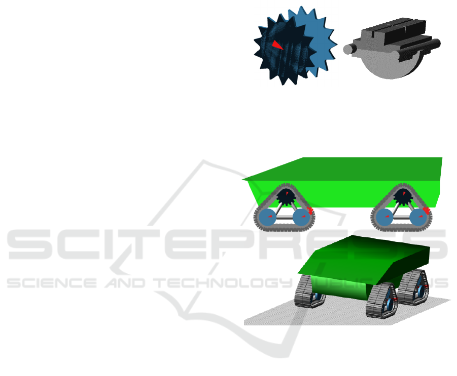
The crawler wheels with the radius of 215 mm.
bring in motion caterpillar encircling using the
toothing with caterpillar tracks. The toothing of the
crawler wheel and tracks is done using contact
interaction with each of the tracks of caterpillar
encircling. In figure 1 (left) shown the visualisation
of crawler wheels.
Caterpillar encircling of each module consists of
29 tracks at 99 mm. intervals. Figure 1 (right) shows
track visualization.
Figure 1: Crawler wheel and track visualization.
As a result of chassis development in ATV
environment we obtained the following view of
AMRC. Figure 2 presents the side view and 3/4.
Figure 2: AMRC model in ATV. Side view and 3/4.
2.4 Non-rigid Support Base Design in
ATV
Non-rigid soil model has a «memory» and keeps a
history of loading. In ADAMS programming system
Tracked Vehicle model nonrigid soil visualized in
the shape of rectangular net, where each element has
a history of loading.
The process of design non-rigid support base in
ATV programming system narrows down to
choosing a property file soil (Ageykin et al., 2010,
Ageykin and Volskaya, 2003, 2008, Bekker, 1960,
Wong, 2010) with preset characteristics from
database.
Property file of non-rigid support base is made as
a set of experimental evidence coefficiencies,
describing one or another soil type. Figure 3 presents
VEHITS 2020 - 6th International Conference on Vehicle Technology and Intelligent Transport Systems
568
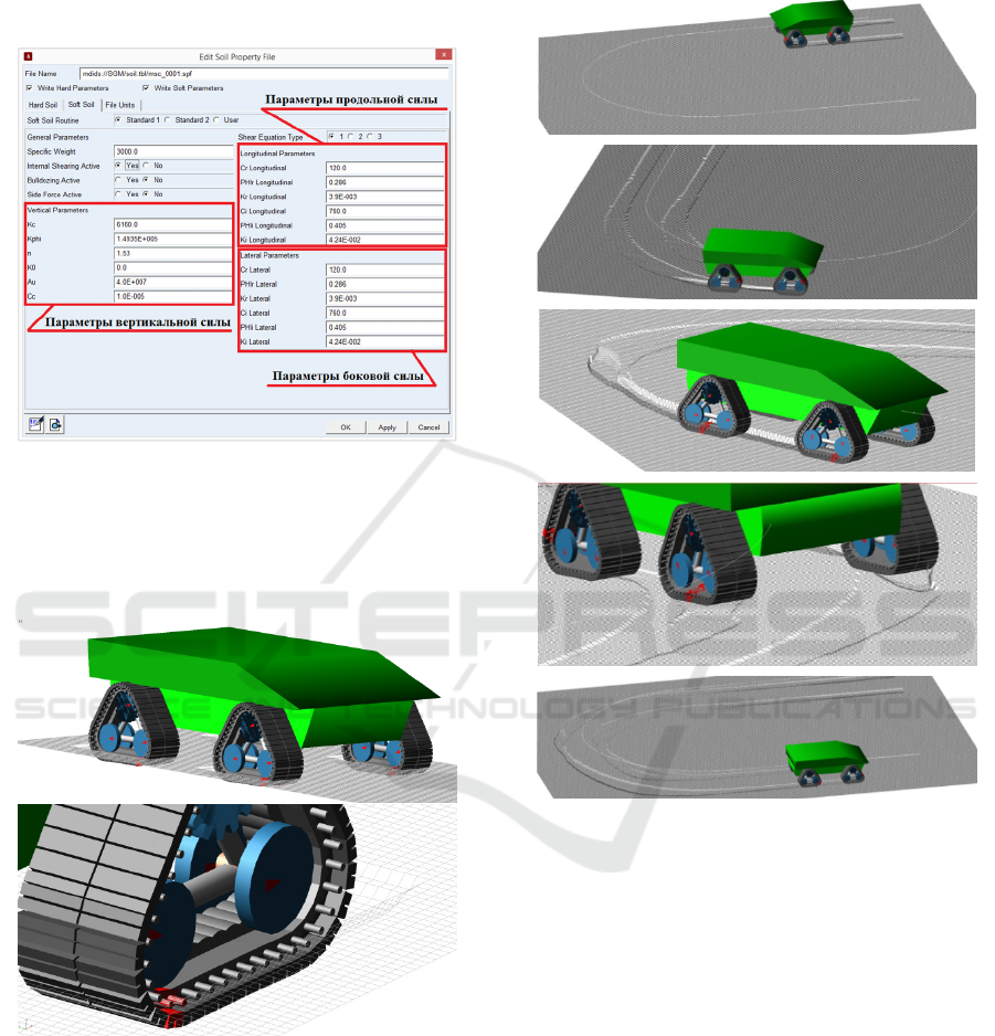
an example of popup window, which contains the
coefficients, necessary for description of parameters
of vertical, lengthway and side force between
supporting base and caterpillar chain track.
Figure 3: Coefficients necessary for description force
interaction non-rigid support base and caterpillar chain
track.
AMRC views on nonrigid soil are shown in
Figure 4.
Figure 4: AMRC on non-rigid soil.
2.5 AMRC Motion Modeling in ATV
For the designed AMRC model we have conducted a
motion modeling on bearing surface with
characteristics close to a sand surface beach line
terrain. The modeling have studied two types of
motion: linear and 180 degree turning with turning
radius to chassis center equals to 5 meters.
Figure 5 demonstrates the fragments of
curvilinear motion.
Figure 5: AMRC curvilinear motion.
As a result of turning on linear and curvilinear
trajectory we obtained the graphs of turning moment
and power on main crawler wheels. We obtained the
values for wheel spinning. The maximum motion
speed was preset at 25 km/hr.
Figure 6 (top) demonstrates examples of turning
moment changes on the main wheels of caterpillar
modules of one bead during linear motion. In figure
6 (bottom) shown the moments on main wheels of
caterpillar modules during the turn.
On grahs in figure 6 (bottom) positive values
correlate to moments on the outside of AMRC,
negative on the inside. The mean of moment on one
bead during linear motion amounted to 172 Нм,
during curvilinear to 195 и 217 Nm respectively for
backward and overleaping chassis beads.
Experimental Theoretical Study of the Mobile Robotic System Movement with Caterpillar-modular Propulsion on the Beach Line Terrain
569
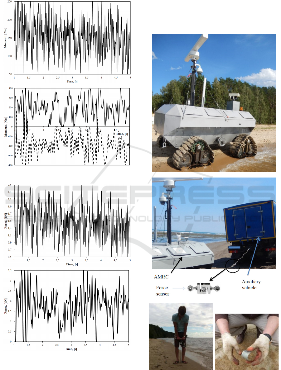
Figure 6: Turning moment behavior graphs.
Figure 7: Behavior graphs of motion resistance force of
AMRC on the sand.
Figure 7 present the change of motion resistance
force of linear motion (top) and curvilinear (bottom)
motion. The mean for linear motion amounted to
1606 N, for curvilinear to 1943 N.
The evidence correlates to conducted
experimental studies.
a
b
c
Figure 8: Experimental studies fragments.
VEHITS 2020 - 6th International Conference on Vehicle Technology and Intelligent Transport Systems
570

3 THEORETICAL RESEARCH
For choosing input data for modeling we have
conducted experimental data for sampling of AMRC
motion resistanse and parameters of support ground.
(Belyaev et al., 2018, 2019 Kurkin et al., 2017,
Makarov et al., 2017) Figure 8a shows AMRC
motion moment alongside shore line. Figure 8b
shows a sampling fragment of resistance force. An
additional vehicle pulled AMRC through the wire
rope with load cell. Figure 8c demonstrates the
moments of sampling physicomechanic
characteristics sand shore. The left side demonstrates
the sampling of resistance of penetration, the right -
soil density.
From the data received we have obtained soil
characteristics included in soil model in ATV. The
mean motion resistance amounted to 1600 N
(Belyaev et al., 2018, Belyaev & Makarov, 2018).
These data was used for model checkout during
AMRC linear motion.
4 CONCLUSIONS
The study presented basic motion equations used in
MSC.ADAMS for machine modeling motion.
The study lists the assumptions used in the
model.
The study designes the AMRC model with
caterpillar-module propulsion.
We have obtained the modeling of linear and
curvilinear AMRC motion on sand support base.
The results include model parameters behavior
graphs in time. As a result, the mean of moment on
one bead during linear motion amounted to 172 Nm,
during curvilinear to 195 and 217 Nm respectively
for backward and overleaping chassis beads. The
mean of motion resistance during linear motion
amounted to 1606 N, during curvilinear to 1943 N.
The experimental studies present the sampling of
resistance force on the real-life object at beach line
terrain. The mean motion resistance amounted to
1600 N.
Amid the experimental data findings adjustments
were made to the model of interest.
The future studies include modeling of on-the-
spot machine turn, the movement on other types of
support bases, the evaluation of operational
efficiency at beachline terrain.
ACKNOWLEDGEMENTS
The results of the given study have been obtained
with financial support of the grants of the President
of the Russian Federation № MD-226.2020.8.
REFERENCES
Ageykin, Ya.S. and Volskaya, N.S., 2003. Dynamics of
the wheeled vehicle when driving on an uneven
ground surface. MGIU, Moscow, 124 p.
Ageykin, Ya.S. and Volskaya, N.S., 2008. Theory of the
vehicle. MGIU, Moscow, 318 p.
Ageykin, Ya.S., Volskaya, N.S. and Chichekin, I.V., 2010.
Passability of vehicles. MGIU, Moscow, 275 p.
Barber, D.M. and Mills, J.P., 2007 Vehicle based
waveform laser scanning in a coastal environment.
Proceedings of 5th International Symposium on
Mobile Mapping Technology, Pradua, Italy.
Bekker, M., 1960 Theory of land locomolion. University
of Michigan, Press, 520 p.
Beliakov, V., Beresnev, P., Filatov, V., et all., 2017.
Coastal monitoring of the Okhotsk Sea using an
autonomous mobile robot. Science of Tsunami
Hazards. 36-1, 1-12.
Belyaev, A. M., Makarov, V. S., Markovnina, A. I., et al.,
2019. Field research of drag-and-traction
characteristics of mobile robotic system in coastal
zone. Paper presented at the Journal of Physics:
Conference Series, 1177(1) doi:10.1088/1742-
6596/1177/1/012050
Belyaev, A. M., Belyakov, V. V. and Makarov, V. S.,
2020. Study of efficiency of a 6x6 all-terrain vehicle in
coastal zone. Paper presented at the IOP Conference
Series: Materials Science and Engineering, 709(4)
doi:10.1088/1757-899X/709/4/044030
Belyaev, A. M. and Makarov, V. S., 2018. Method of
assessment of special wheel chassis mobility in cases
of sand-gravel bases crossing. Paper presented at the
IOP Conference Series: Earth and Environmental
Science, 194(2) doi:10.1088/1755-1315/194/2/022019
Belyaev, A. M., Zakharov, A. A., Makarov, V. S., et al.,
2018. Analysis of the main bases of the coastal zone,
as a pathway for the movement of special vehicle and
monitoring complexes. Paper presented at the IOP
Conference Series: Materials Science and Engineering,
386(1) doi:10.1088/1757-899X/386/1/012002
Bio, A., Bastos L., Granja, H., et al., 2015 Methods for
coastal monitoring and erosion risk assessment: two
Portuguese case studies. Journal of Integrated Coastal
Zone Management. 15-1, 47 – 63.
Didier, D., Bernatchez, P., Boucher-Brossard, G., et al.,
2015. Coastal Flood Assessment Based on Field
Debris Measurements and Wave Runup Empirical
Model. J. Mar. Sci. Eng. 3, 560 – 590.
Incoul, A., Nuttens, T., De Maeyer, P., et al., 2014. Mobile
laser scanning of intertidal zones of beaches using an
Experimental Theoretical Study of the Mobile Robotic System Movement with Caterpillar-modular Propulsion on the Beach Line Terrain
571

amphibious vehicle. INGEO 2014: 6th international
conference on engineering surveying, Prague, Czech
Republic, 87 – 92.
Kramer, J. and Hunter, G., 2007. Performance of the
StreetMapper Mobile LiDAR Mapping System in
«Real World» Projects». Photogrammetric Week ’07,
215 – 225.
Kurkin, A., Makarov, V., Zeziulin, D., et al., 2017. Study
of coastal soil surfaces of sakhalin island. Paper
presented at the 13th International MEDCOAST
Congress on Coastal and Marine Sciences,
Engineering, Management and Conservation,
MEDCOAST 2017, 2, 775-785
Kurkin, A., Pelinovsky, E., Tyugin, D. et al., 2015.
Autonomous Robotic System for Coastal Monitoring.
Twelfth international conference on the Mediterranean
coastal environment (MEDCOAST 15), Vols 1 and 2,
933-943.
Kurkin, A., Pelinovsky, E., Tyugin, D., et al., 2017.
Unmanned Ground Vehicles for Coastal Monitoring.
International Journal of Imaging and Robotics, 17-1,
64-75
Kurkin, A.A., Tyugin, D.Yu., Kuzin, V.D., et al., 2017.
Autonomous Mobile Robotic System for Environment
Monitoring in a Coastal Zone. Procedia Computer
Science, 103, 459 – 465.
Makarov, V., Filatov, V., Vahidov, U.,et al., 2017. Study
of trafficability conditions of typical soils of coastal
zones of sakhalin island (Russian Federation). Paper
presented at the 19th International and 14th European-
African Regional Conference of the ISTVS
Yu Tyugin, D., Zeziulin, D. V., Kurkin, A. A., et al., 2018.
Development of a mobile robot group for coastal
monitoring. Paper presented at the IOP Conference
Series: Materials Science and Engineering, 386(1)
doi:10.1088/1757-899X/386/1/012009
Wübbold, F., Hentschel, M., Vousdoukas, M., et al., 2012.
Application of an autonomous robot for the collection
of nearshore topographic and hydrodynamic meas-
urements. Coastal Engineering Proceedings. 1, 53.
Wong, J.Y., 2010. Terramechanics and Off-Road Vehicle
Engineering. Elsevier, 463 p.
Zaytsev, A., Belyakov, V., Beresnev, P. et al., 2015.
Coastal monitoring of the Okhotsk sea using an
autonomous mobile robot. Science of Tsunami
Hazards. Volume 36, Issue 1, 2017, Pages 1-12.
VEHITS 2020 - 6th International Conference on Vehicle Technology and Intelligent Transport Systems
572
