
Development of Portable Sound Source Direction Estimation Device
Kenta Goto
1,
*
, Hiroki Kijima
2
, Mizuki Usuda
2
and Yoshihisa Uchida
1,2
1
Graduate School of Engineering Mechanical Engineering Course, Aichi Institute of Technology, Yakusa Yachigusa1247,
Toyota, Japan
2
Department of Mechanical Engineering, Faculty of Engineering, Aichi Institute of Technology, Toyota, Japan
Keywords: Sound Source Direction Estimation, Wearable, CASH-H, Hearing Loss.
Abstract: In this study, we propose a portable sound source direction estimation device (CASH-H) for people suffering
from hearing loss and for the elderly. CASH-H, which is the proposed device, is one that estimates sound
source direction by using sound signals from two microphones, and then transmits the estimated direction
data to the user. This study proposes and evaluates a sound source estimation method by signal processing.
The sound source direction is calculated from the reception time difference between the two microphone
signals. In order to improve the measurement accuracy and measurable distance, an amplifier circuit and an
IIR digital filter were used. The sound source direction estimation was performed with a mean angle error of
1.09 ° and angle standard deviation of 4.23 °. The measurable distance was up to 40 m under the experimental
conditions.
1 INTRODUCTION
According European Hearing Instrument
Manufacturers Association (EHIMA) and Japan
Hearing Instruments Manufacturers Association
(JHIMA), 10% of the population of EU or Japan self-
report as suffering from hearing loss (Laureyns, M.,
2016, Japan Trak, 2018). Reports also indicated that
most people who report themselves to have hearing
loss happen to be 65 years and older, i.e., higher the
percentage of the population that is 65 years and
older, higher the percentage of the population that
experiences hearing difficulties. The number of
people with hearing loss is expected to increase in the
future.
Hearing loss can put one at risk as it reduces their
alertness to the environment around them. For
example, the inability to hear the horn of a car in an
emergency increases the risk of contact accident.
However, the hearing aids protect the people with
hearing loss from any such dangers; hearing aids
detect the warning signs so that there is no need for
the user to detect the signs themselves. Hearing aids,
although effective, are often difficult to use and
maintain in addition to being costly. Therefore, there
is a need to develop simple and portable sound source
direction estimation devices.
*
https://fpms.aitech.ac.jp/Main.php?action=top&type=form
A lot of research concerning sound source
localization has been conducted (Nakadai, K., 2006,
Ishi, C.T., 2009). Most of the sound localization
technologies use the MUSIC (Multiple Signal
Classification) algorithm, which is a well-known
high-resolution method. And recently, the high speed
of computer processing is boosted, and the
effectiveness of sound source position using deep
neural network has been shown (Ma, N., 2018,
Ravulakollu, K.K., 2011, He, W., 2018). In order to
improve the accuracy, it is effective to understand the
propagation of sound wave around microphones
(Hwang, S., 2007, Ma, N., 2015, Kim, K., 2012,
Murray, J.C., 2006). The Head-related transfer
function (HRTF) is one of the useful tools. Research
on HRTF has been carried out, and data sets have
been published in various institutions (Watanabe, K.,
2014).
However, this method usually requires heavy
computational costs and other prerequisites. Most of
these devices are large because they make use of a
microphone array that is too large to be carried and
are intended for use in a well-arranged room.
In this study, we propose a simple and portable
sound source direction estimation device (CASH-H)
for people suffering from hearing loss and for the
elderly. The proposed CASH-H is a device that
Goto, K., Kijima, H., Usuda, M. and Uchida, Y.
Development of Portable Sound Source Direction Estimation Device.
DOI: 10.5220/0009779806150620
In Proceedings of the 17th International Conference on Informatics in Control, Automation and Robotics (ICINCO 2020), pages 615-620
ISBN: 978-989-758-442-8
Copyright
c
2020 by SCITEPRESS – Science and Technology Publications, Lda. All rights reserved
615
estimates the sound source direction by using sound
signals from two microphones, and then transmits the
estimated direction data to the user. In this study, we
propose a sound source direction estimation method
by signal processing. In order to improve the
measurement accuracy and measurable distance, an
IIR (Infinite Impulse Response) digital filter is used.
The sound source direction is calculated from the
reception time difference between two microphone
signals. Therefore, the developed device is made
more user friendly and affordable as a result of the
functionality of the warning sound being limited
specifically to the detection of warning sounds. The
accuracy of the estimated direction was evaluated at
several conditions.
The proposed sound source direction estimation
method understands that the estimation angle
accuracy is inferior to other studies. However, our
goal is not to estimate high accuracy, but to detect
danger and transmit it to the user repeatedly in real
time. Therefore, the estimated accuracy is about 10
degrees. In addition, if the period of repeated
measurement can be shortened, it is also considered
to be possible to increase the estimation accuracy by
integrating the data.
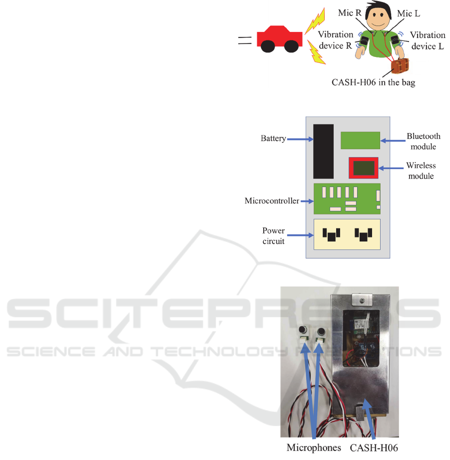
2 CASH-H
The schematic diagram of the developed CASH-H06
is shown in Fig.1, which illustrates the components
that comprises CASH-H06. The components include
two microphones with an amplifier circuit, a main
unit for control and power supply, and a vibration
device for communicating the estimated result to the
user. Two clip type microphones are attached to the
collar of the user’s clothes, and the main unit is placed
in a bag. The vibration devices are attached to the
user’s left and right arms, onto which the estimated
result is delivered in the form of vibrations of varying
strength. In addition, the result can also be displayed
on the user’s smart phone. The clip type microphones
and vibration device reduce the discomfort
experienced by the user while wearing it. The main
unit, which consists of a microcontroller as a control
circuit, wireless communication circuit, and battery
with a power circuit, is shown in Fig.2. A photograph
of the two microphones and main unit is shown in
Fig.3. The main unit, with a length of 148 mm, width
of 74 mm, thickness of 40 mm, and weight of 204 g,
has a size comparable to that of a smart phone.
Figure 1: CASH-H06 overview.
Figure 2: CASH-H06 configuration.
Figure 3: Photograph of CASH-H06.
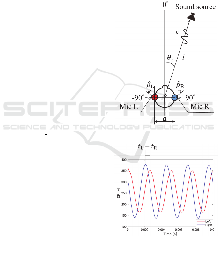
3 METHOD FOR SOUND
SOURCE DIRECTION
ESTIMATION
The sound source direction was calculated from the
reception time difference between two microphone
signals. Two microphones (Mic L and Mic R) were
placed at distance a[m] from each other, as shown in
Fig.4. β[°] is the mounting angle of the microphone.
It is assumed that the warning sound occurs at an
ICINCO 2020 - 17th International Conference on Informatics in Control, Automation and Robotics
616
angle θ [ °] and a distance l[m] from the center
between the microphones. The sound source is
assumed to be a point sound source at a sufficiently
far distance from the microphones. In addition, it is
assumed that there is no influence of the reflected
wave. The microphones on the left and right detect a
warning sounds and output them as sound signal
S
M
(N)S
ML
(N), S
ML
(N) . The sound signal is
amplified by the amplification circuit. The amplified
signal S
A
(N)S
AL
(N), S
AL
(N) is then sent to the
microcontroller in the main unit. The amplification
signal is given by the following equation:
S
A
(N)=A×S
M
(N)
(1)
where N represents the number of samples, and A is
the amplification factor. Since this device is intended
for outdoor use, it is expected that a lot of noise will
interfere with the intended signal. Therefore, the
amplification signal is passed through an IIR digital
filter applies an IIR digital filter to eliminate high-
frequency noise. The processing signal
S
F
(N)S
FL
(N), S
FL
(N) , which is output after
filtering, is expressed as follows:
S
F
(N)=b
1
S
F
N-1
+b
2
S
F
N-2
+d
1
S
M
(N)
+d
2
S
M
N
-1
+d
1
S
M
(N-2)
(2
)
The coefficients b
1
,b
2
,d
1
,and d
2
are described by
equation 3 and 4.
b
1
=
8-2T
2
ω
c
2
B
, b
2
=
2
√
2ω
c
T-T
2
ω
c
2
-4
B
, d
1
=
T
2
ω
c
2
B
, d
2
=
2T
2
ω
c
2
B
(3
)
B=4+2
√
2ω
c
T+T
2
ω
c
2
(4)
T[s] represents the sampling period, and ω
c
[rad/s] is
the cut-off angular frequency. Using cut-off
frequency f
IIR
[Hz], ω
c
can be represented as follows:
ω
c
=2πf
IIR
(5)
The typical processing signal S
F
(N)S
FL
(N), S
FL
(N)
is shown in Fig.5. The two signals of S
FL
(N) and
S
FR
(N) are time-varying depending on the angle θ.
Therefore, from the reception time difference 𝑡
𝑡
𝑡
[s] between each processing signal obtained
by peak extraction, the estimated angle of the sound
source 𝜃
[°], is calculated by equation 6.
θ
i
=sin
-1
k
c
a
t=sin
-1
Kt
(6)
c[m/s] represents the speed of sound, k is a coefficient
depending on the frequency, and K=kc/a. The K
depends on the frequency and the mounting position
of the microphones. Therefore, the coefficient is
determined from the characteristics obtained by the
sound from a known sound source for frequency and
angle before the experiment.
Figure 4: Positional relationship between CASH-H and
sound source.
Figure 5: Typical processing signal S
F
(N)S
FL
(N), S
FL
(N).
Development of Portable Sound Source Direction Estimation Device
617
4 RESULTS AND DISCUSSION
In the experiment, the CASH-H06 was placed on a
rotating table, and a car horn was sounded as a
warning sound from a distance. The relative angle θ
between CASH-H06 and the sound source was
changed by the rotating table. Experimental
conditions of N 4000, T5.0 μs, 𝑎 0.2 m, β
𝛽
R
𝛽
L
90 °, f=400 Hz, and 𝑙15 m were
used. These conditions are selected as a typical
mounting position and angle of microphone and
frequency and position of a car horn as a sound
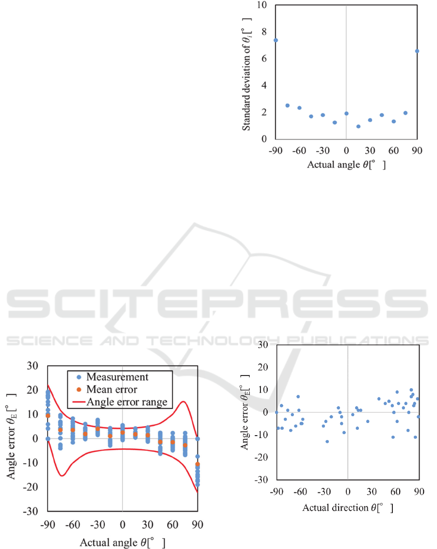
source. A typical result of the estimated angle error
𝜃
𝜃
θ in comparison to the actual angle is
shown in Fig.6. The estimated angle 𝜃
is calculated
by equation 6 where the coefficient K is determined
by preliminary experiments to be 540. Each of the
experiments was repeated 20 times. The results
indicated that the angle error was in the range of
±20 °. The standard deviation of the angle is shown in
Fig.7. A mean angle error of 1.09 ° and an angle
standard deviation of 4.23 ° were observed. The
estimation angle is determined from trigonometric
function as described by equation 6. Therefore,
variations in estimation accuracy occur depending on
the actual angle. Angle error range obtained from the
standard deviation of the measured reception time
difference and the trigonometric function is the height
differences between the curves, as shown by the red
line in Fig.6. The angle error of ±90 ° is greater than
other angles.
Figure 6: A typical result of the estimated angle error.
Figure 7: Standard deviation of the estimated angle.
For comparison purposes, the same experiment was
conducted on a blindfolded person who did not suffer
from hearing loss. The results of this experiment are
shown in Fig.8. The experiment was conducted on 5
different subjects and experimental conditions were
similar to those of previous experiment in Fig.6. The
mean error was 4.54 ° and the standard deviation was
3.20 ° from the experimental results. This result was
almost same as that involving the CASH-H06
devices. Therefore, it was concluded that the sound
source direction estimation of the CASH-H06 devices
demonstrated sufficient accuracy for human use.
Figure 8: Angle estimation accuracy from hearing alone.
It is assumed that the microphone is attached to the
user's clothes, and the influence on the angle
estimation accuracy of the distance between the
microphones is evaluated. The characteristics of the
angular error relative to the distance between the
ICINCO 2020 - 17th International Conference on Informatics in Control, Automation and Robotics
618
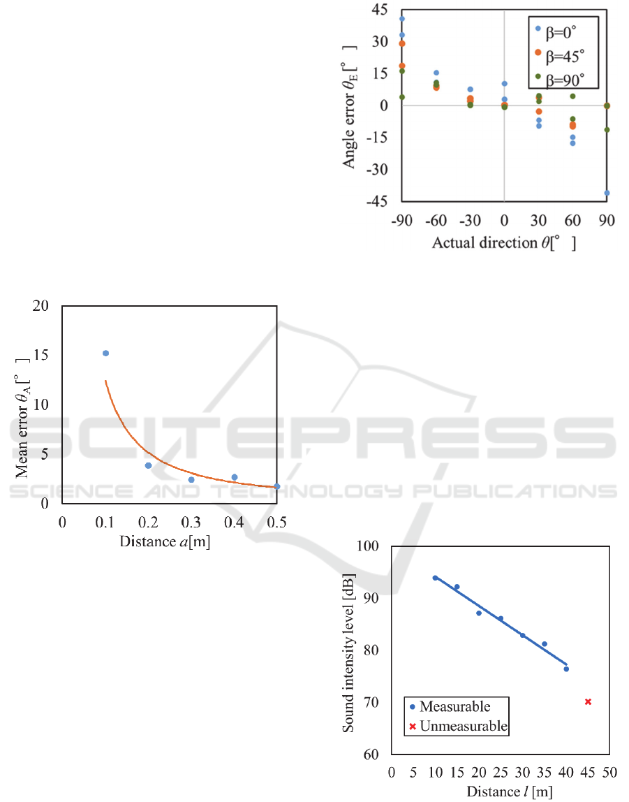
microphones are shown in Fig.9. The result shows
that the mean error decreases with increasing distance
a. The longer the distance between the microphones,
the longer is the reception time difference between
the left and right signals, which reduces the error.
However, the problem is that the reception time
difference exceeds one period of the signal when the
distance is longer than 0.3 m. In order to correctly
estimate the angle, it is thus necessary to identify the
reception time of the same signal in the left and right
signals. Although identification is possible by adding
signal processing, CASH-H06 uses a distance of 𝑎
0.2 m between the microphones, which does not
exceed one period. The estimation accuracy does not
change much, even if the distance is increased. In
addition, this reduces the computational costs and
improves user convenience by reducing the size of the
unit attached to the body.
Figure 9: Effect of distance between microphones.
The influence of the mounting angle β of the
microphone on the angle estimation accuracy was
evaluated. The characteristics of the angular error
relative to the mounting angle of the microphone are
shown in Fig.10. In this result, the estimated angle
was calculated using the coefficient K, which was
calibrated when the angle is 90 ° . The standard
deviations when β is 0,45,and 90 ° are 14.33 °, 8.03
°, and 4.95 °, respectively. It was found that the
mounting angle error of up to 45° was not greatly
influenced by the accuracy of the estimated angle.
Therefore, it was concluded that CASH-H06 can be
used regardless of the mounting angle.
Figure 10: Effect of the mounting angle of the microphones.
Fig.11 shows the sound intensity level as a function
of the distance l. the experimental angle condition
was θ= 0 °. It was found that it is possible to estimate
the sound source direction when the intensity level is
70 dB or more. Since the Signal/Noise (S/N) ratio of
the signal decreases with decreasing amplitude, the
reception time difference of the signal cannot be
detected when the sound intensity level is 70 dB or
less. Therefore, in these experimental conditions, the
measurable distance was up to 40 m. It is possible to
measure even at a low sound intensity level if the
amplification factor can be increased, but it is
necessary to adjust the parameters of the amplifier
circuit and the IIR filter because the S/N ratio
decreases.
Figure 11: Relationship between sound intensity level and
distance l.
Development of Portable Sound Source Direction Estimation Device
619

5 CONCLUSIONS
In this study, a simple and portable sound source
direction estimation device called CASH-H is
proposed, and the accuracy of its direction estimation
is evaluated.
The proposed CASH-H device estimates the
sound source direction using sound signals from only
two microphones and transmits the estimated
direction to the user. In order to improve the
measurement accuracy and measurable distance, an
amplifier circuit and an IIR digital filter were used.
The sound source direction estimation was performed
with a mean angle error of 1.09 ° and angle standard
deviation of 4.23 °. The measurable distance was up
to 40 m under the experimental conditions.
The experiments have been undertaken in very
controlled conditions. Therefore, in the future work,
we will conduct experiments and evaluations under
multiple sound sources and noise environments. It is
also scheduled to evaluate the estimation accuracy by
changing the frequency of the sound source. In
addition, if the period of repeated measurement can
be shortened, it is considered to be possible to
increase the estimation accuracy by integrating the
data. Furthermore, since it is possible to distinguish
the front and rear of the sound source, it is possible to
estimate 360 degrees.
ACKNOWLEDGEMENTS
This work was partially supported by JSPS
KAKENHI Grant Number JP17K06279.
REFERENCES
Laureyns, M., Best, L., Bisgaard, N., Hougaard, S., 2016.
Getting our numbers right on Hearing Loss – Hearing
Care and Hearing Aid Use in Europe.
Japan Hearing Instruments Manufacturers Association,
2018. JapanTrak 2018.
Nakadai, K., et al., 2006. Robust Tracking of Multiple
Sound Sources by Spatial Integration of Room and
Robot Microphone Arrays. In ICASSP 2006, 2006
IEEE International Conference on Acoustics Speech
and Signal Processing Proceedings.
Ishi, C.T., et al., 2009. Evaluation of a MUSIC-based Real-
time Sound Localization of Multiple Sound Sources in
Real Noisy Environments. In IROS 2009, RSJ
International Conference on Intelligent Robots and
Systems.
Ma, N., et al., 2018. Robust binaural localization of a target
sound source by combining spectral source models and
deep neural networks. IEEE / ASME Transactions on
Mechatronics.
Ravulakollu, K. K., Erwin, H., Burn, K., 2011. Improving
Robot-Human Communication by Integrating Visual
Attention and Auditor y Localization using a
Biologically Inspired Model of Superior Colliculus.
He, W., et al., 2018. Deep Neural Networks for Multiple
Speaker Detection and Localization. 2018 IEEE
International Conference on Robotics and Automation
(ICRA).
Hwang, S., et al., 2007. Sound Direction Estimation using
Artificial Ear. In ICCAS 2007, International
Conference on Control, Automation and Systems.
Ma, N., et al., 2015. Exploiting top-down source models to
improve binaural localisation of multiple sources in
reverberant environments. In INTERSPEECH 2015,
16th Annual Conference of the International Speech
Communication Association.
Kim, K., Choi, A., 2012, Binaural Sound Localizer for
Azimuthal Movement Detection Based on Diffraction.
Sensors.
Murray, J. C., et al., 2006. Bioinspired Auditory Sound
Localisation for Improving the Signal to Noise Ratio of
Socially Interactive Robots. In IROS 2009, RSJ
International Conference on Intelligent Robots and
Systems
Watanabe, K., et al., 2014. Dataset of head-related transfer
functions measured with a circular loudspeaker array.
Acoustical Science and Technology.
ICINCO 2020 - 17th International Conference on Informatics in Control, Automation and Robotics
620
