
Optimization of a Single-stage Air Starter Turbine
Grigorii Popov
a
, Oleg Baturin, Vasilii Zubanov
b
, Daria Kolmakova
c
, Anastasia Korneeva
and Andrei Volkov
Samara National Research University, Samara, Russia
Keywords: Auxiliary Power Unit, Air Turbine, Optimization, Joint Operation, Gas Turbine Engine, Start-up Time,
Torque.
Abstract: The paper describes the process of optimizing the blades of a starter air turbine for a gas turbine engine launch
system. This task was initiated by the necessity to use an existing turbine when starting a new engine. During
the study, it was found that the turbine, although it ensures the conditions for the joint operation with the
auxiliary power unit turbine and meet the strength constraints, it does not allow to start the engine within the
required time. As a result of studies using mathematical optimization methods involving commercial
programs, a variant was found to modernize the baseline turbine, which provides an acceptable value of torque
on the shaft with an adequate start-up time at all operating modes with minimal design changes.
NOMENCLATURE
GTE - gas turbine engine
APU - auxiliary power unit
NGV - nozzle guide vane
ATS - air turbo starter
IGV - inlet guide vane
𝐾
- mass flow parameter
𝐾
- power parameter
P - pressure
T - temperature
G - mass flow rate
𝛼
- IGV stagger angle
𝜋 - pressure ratio
Δ𝐺 - losses (bleeding) of air flow in the aircraft
Δ𝑝
∗
- total pressure losses in the aircraft ducts
Δ𝑇
∗
- total temperature losses in the aircraft ducts
N - power
𝑝
- ambient pressure
𝑡
- ambient temperature
n - rotational speed
M - torque
- time
a
https://orcid.org/0000-0003-4491-1845
b
https://orcid.org/0000-0003-0737-3048
c
https://orcid.org/0000-0003-2806-3073
1 INTRODUCTION
The start-up of an aircraft gas turbine engine is an
important mode that largely determines the safety,
operational efficiency and reliability of the engine
and the entire aircraft. The gas turbine engine start-up
system includes a set of various devices and units: a
starter, auxiliary power unit, air and fuel
communications, automatic control system,
transmission, power supply system, ignition system,
etc. For reliable engine starting, the operation of all
these systems must be consistent with each other
(Inozemcev et al., 2008).
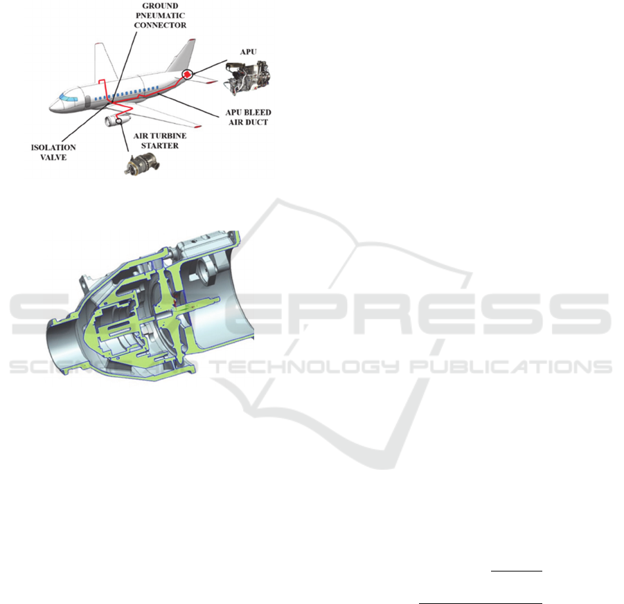
Currently, the civil aircraft engine starting system
is often based on an air turbine mechanically
connected to the GTE rotor, receiving compressed air
from the APU compressor (Figure 1).
The group of the paper’s authors is employed by
the Department of Aircraft Engine Theory of Samara
National Research University (Samara University,
2020) and has extensive experience in studying and
improving the working process of various
components of a gas turbine engine (Marchukov et
al., 2017; Matveev et al., 2018). Currently, the
scientific group takes part in joint work in the
interests of various enterprises that are the part of the
Popov, G., Baturin, O., Zubanov, V., Kolmakova, D., Korneeva, A. and Volkov, A.
Optimization of a Single-stage Air Starter Turbine.
DOI: 10.5220/0009769501550162
In Proceedings of the 10th International Conference on Simulation and Modeling Methodologies, Technologies and Applications (SIMULTECH 2020), pages 155-162
ISBN: 978-989-758-444-2
Copyright
c
2020 by SCITEPRESS – Science and Technology Publications, Lda. All rights reserved
155
United Engine Corporation (Russia) (United engine
corporation, 2020). In particular, one of the
Customers set the task of assessing the feasibility of
using an air turbostarter manufactured at the
enterprise to launch a new turbofan engine of the
same class. The design of the considered ATS is
shown in Figure 2.
Figure 1: Concept scheme of the starting system with an air
turbine.
Figure 2: Design of the investigated starter air turbine.
The team was assigned the following tasks:
1) the ATS operation must be coordinated with
the operation of the APU at all operating modes
(under various atmospheric conditions, flight
speeds and altitudes);
2) start-up time must be minimized (the minimum
allowed time was set);
3) the torque on the output shaft must not exceed
the maximum value according to the strength
conditions of the reduction gearbox and gear
box of the engine drives.
In other words, the main task was to modify the
flow part of the existing ATS so that it would satisfy
the above conditions when working in a modified
launch system (another gas turbine engine and APU).
Moreover, the design of the baseline turbine must be
kept as much as possible to reduce costs. Thus, the
task is a typical optimization problem in which the
turbine geometry must be changed (considering
various constraints: structural and strength) to
improve the required criterion (start-up time).
In open scientific and technical sources, there are
many publications on the modernization and
optimization of the turbine workflow (Marchukov et
al., 2018; Châtel et al., 2019., Asgarshamsi et al.,
2014). However, all of them are aimed at improving
the efficiency of turbines or their reliability. In current
case, the unusual optimization criteria take place and
it is necessary to check the condition for the joint
operation of the ATS and APU and to calculate the
start-up time of the gas turbine engine during
optimization.
To solve the problem, an algorithm was developed
for matching the working process of the APU and the
air turbine used to start the engine. This method was
described in detail in (Zubanov et al., 2019).
The essence of the method is that the characteristics
of the APU and ATS are converted to a general form
of the dependence of the reduced flow parameter K
G
on the expansion ratio of air in the turbine 𝐾
𝑓𝜋
. The intersection of the lines of the APU and
turbine operating modes suggests that the conditions
for joint work are fulfilled at these modes. At the
intersection points of the characteristics 𝐾
𝑓𝜋
and 𝐾
𝑓
𝜋
, the parameters at
the APU outlet 𝑝
∗
, 𝑇
∗
, 𝐺
are
calculated and with their help the characteristics of
the turbine (in particular, the dependence of power on
rotational speed) are determined under the found
conditions. Then, using the ATS power
characteristics, the start time of the gas turbine engine
is determined. The algorithm for its calculation is
described in (Zubanov et al., 2019). The conformity
of the maximum torque to the strength constraints is
also checked.
Thus, based on the intersection points of the above
characteristics, the physical characteristics of the
ATS are found when working together with the APU
at all its modes.
The flow parameter K
G
is a physical quantity that
is calculated using the following expression:
𝐾
𝐺
∙
𝑇
∗
𝑝
∗
,
(1)
where 𝐺
- the value of air mass flow rate
through the ATS;
𝑇
∗
- the value of the total temperature at
the ATS inlet;
𝑝
∗
- the value of the total pressure at the
ATS inlet.
SIMULTECH 2020 - 10th International Conference on Simulation and Modeling Methodologies, Technologies and Applications
156
When calculating the flow parameter K
G
for the
APU, leakages and pressure and temperature losses in
the pipelines of the launch system on the way to the
turbine are considered.
𝐾
𝐺
∆G
∙
𝑇
∗
∆𝑇
∗
𝑝
∗
𝛥𝑝
.
∗
,
(2)
𝜋
𝑝
∗
𝛥𝑝
.
∗
𝑝
,
(3)
where 𝐾
– APU air mass flow parameter
determined at the inlet of the ATS considering losses
in the pipelines;
𝜋
– pressure ratio in the ATS determined by
the parameters of the air at the inlet to the ATS
considering losses in the pipelines;
𝐺
– the value of the mass flow rate of air
taken from the APU considering losses in the
pipelines,
:
𝐺
𝐺
∆G
(4)
𝑇
∗
– the value of the temperature of air taken
from the APU considering losses in the pipelines,
К:
𝑇
∗
𝑇
∗
∆𝑇
∗
,
(5)
𝑝
∗
– the value of the total pressure of air
taken from the APU considering losses in the
pipelines,
:
𝑝
∗
𝑝
∗
𝛥𝑝
.
∗
,
(6)
𝑝
– atmospheric pressure for altitude in standard
atmospheric conditions,
.
Values of losses of mass flow rate, temperature
and pressure in the system are set by the Customer
according to the experience of operating an engine of
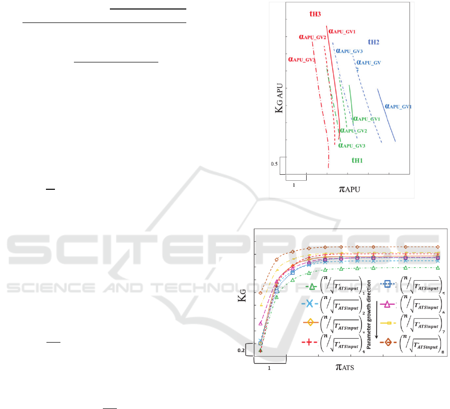
a similar class. The dependence 𝐾
𝑓𝜋
obtained for the used APU is shown in Figure 3.
Characteristics of the turbine of the form
𝐾
𝑓𝜋
(Figure 4) were obtained by CFD
modelling of the working process in the investigated
turbine (Figure 2). Its mathematical model was
created using NUMECA software system. The model
included a structural grid of finite volumes of 92
thousand elements. The value of the parameter y+ did
not exceed 1. The Spalart-Allmaras turbulence model
was used. In general, the settings of the numerical
model of an air turbine corresponded to the typical
settings used in the calculation of the working process
in turbines (Popov et al., 2018).
Figure 3: Characteristics 𝐾
𝑓𝜋
of used APU.
Figure 4: Mass flow characteristics 𝐾
𝑓𝜋
of
investigated air turbine.
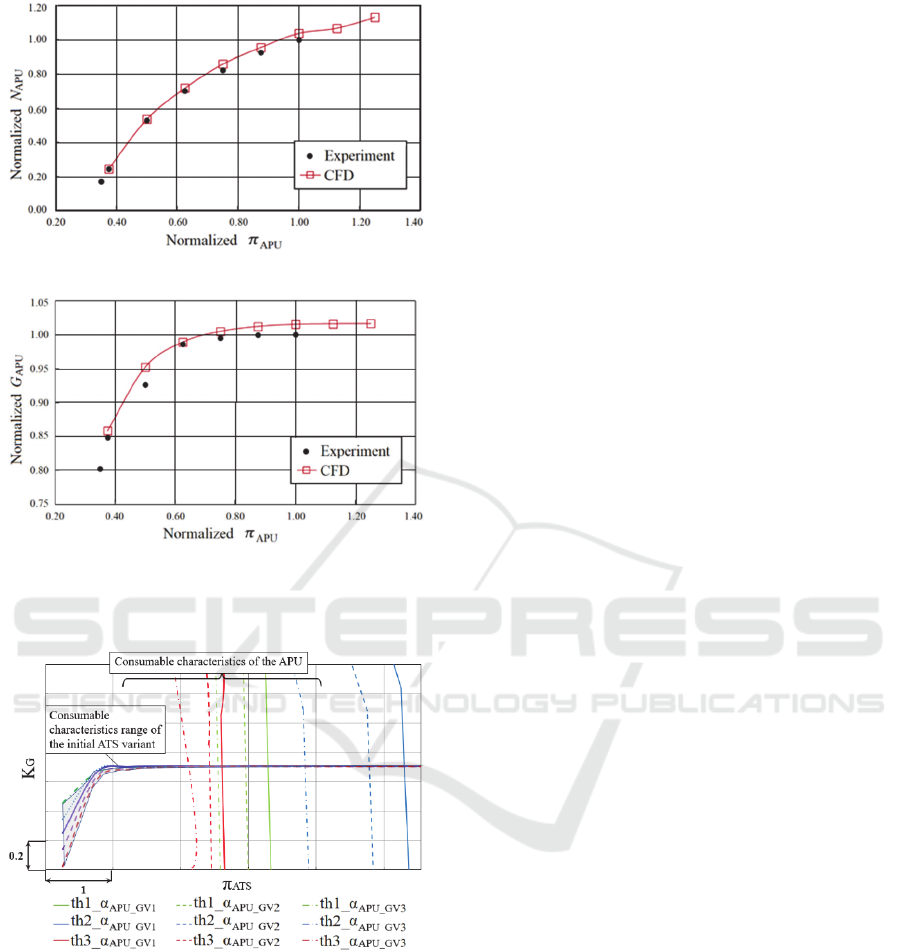
The calculation results obtained using the created
calculation model were compared with the
experimental data provided by the customer (Figure
5). The relative error in determining the ATS power
was less than 2.5%, and the air mass flow rate was
less than 2%.
The characteristics 𝐾
𝑓𝜋
for the ATS and
APU were combined at one diagram (Figure 6).
Optimization of a Single-stage Air Starter Turbine
157
Power characteristics
Mass flow characteristics
Figure 5: Comparison of calculation results obtained with
the created computational model with experimental data.
Figure 6: Combined flow characteristic of the APU and
ATS.
As can be seen from Figure 6, all the lines of APU
and ATS operating modes intersect, which indicates
that the condition for their joint operation is fulfilled
at all operating modes. However, it was found during
the calculation, that the start-up time of the gas
turbine when using the ATS exceeds the value
specified in the technical requirements by 12.6%. At
the same time, the maximum torque on the turbine
shaft did not exceed the permissible value. Thus, it is
necessary to increase the turbine power (without
exceeding its limit value) and the air flow through it
in order to reduce the start-up time to use the turbine
for a new GTE start system.
Analysis of the turbine working process showed
that the required increase in the turbine power and
mass flow rate can be achieved with minimal changes
in the initial design only by modernizing the shape of
the nozzle guide vanes. In the other words, the
modernization of the existing ATS to the new
requirements can be performed while substantially
preserving the design. In fact, only one part will be
changed that is the nozzle block.
2 PARAMETRIC STUDIES
To search for a possible solution, parametric studies
were conducted on the influence of these parameters
on the start-up time.
2.1 Changing the NGV Stagger Angle
During the study of the influence of the stagger angle
of NGV on the flow rate of the working fluid and the
power of the turbine, the angle varied in the range of
+2 relative to the initial value. In total, five points
were considered (including the initial geometry) with
a step of 0.5. A larger change in the angle will lead
to a change in the design of adjacent parts and a
significant amount of alteration of the original design.
The obtained dependences of the mass flow
parameter 𝐾
, start-up time and torque on changes in
NGV stagger angle are shown in Figure 7. It can be
seen that with a maximum increase in the NGV
stagger angle, the start-up time of the gas turbine
engine was reduced by only 7.6%. This value is 5.7%
higher than the limit value (i.e., such a turbine does
not satisfy the requirements). The maximum value of
torque was 27.5% less than the maximum allowable,
which meets the requirements of the technical
specifications. Thus, changing only the stagger angle
within the existing constraints on the axial length of
the NGV part is not enough to increase the turbine
power and to reduce the start-up time of the GTE.
2.2 Trimming the Trailing Edge of
NGV
Five variants for trimming the trailing edge of the
NGV were considered (Figure 8). The dependences
of the flow rate parameter 𝐾
, start-up time and
torque on the value of trimming the NGV trailing
edge are obtained. They are shown in Figure 8. It can
SIMULTECH 2020 - 10th International Conference on Simulation and Modeling Methodologies, Technologies and Applications
158
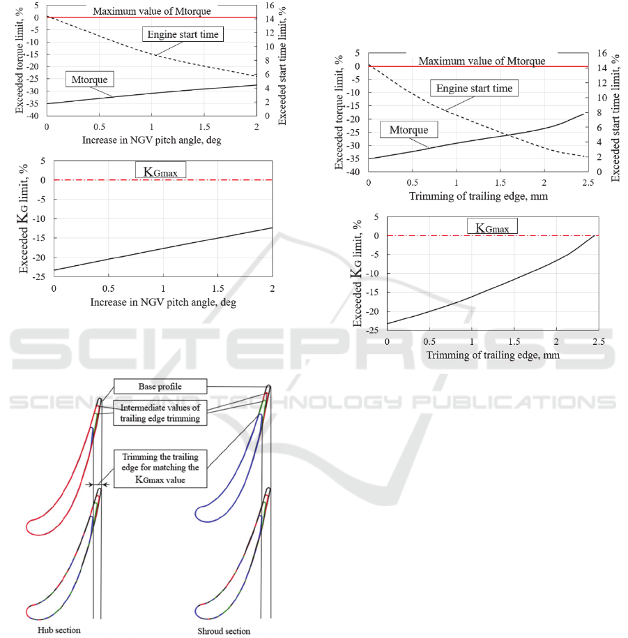
be seen from the presented results that, the start-up
time was reduced by 10.7% by trimming the NGV
trailing edge, which is 2.1% more than the maximum
allowable τ_max. The maximum torque value was
21.8% less than the maximum allowable M
torque_max
.
Figure 7: Dependences of the parameters of the starter
turbine and the start-up time of the gas turbine engine on
the stagger angle of the ATS NGV.
Figure 8: The hub and shroud sections of the NGV variants
with trimming trailing edge.
Thus, trimming the NGV trailing edge also does
not provide the GTE start-up time specified in the
technical task. During the study, it was found that the
proposed modernization options cause significant
deviations of the inlet flow angles for the rotor blade,
which are the reason of significant dynamic stresses
in it.
Thus, none of the considered variants of ATS
modernization satisfies the requirements of the
technical specifications with its design is preserved to
the maximum. For this reason, it was decided to use
mathematical optimization methods to find an
acceptable variant.
Figure 9: Dependences of the mass flow parameter 𝑲
𝑮
,
start-up time and torque on the value of trimming the NGV
trailing edge.
3 OPTIMIZATION ALGORITHM
FOR STARTER AIR TURBINE
A further search for a new shape of ATS NGV was
carried out using multicriteria mathematical
optimization methods. For this, an algorithm was
developed that is built around the IOSO optimizer
program (IOSO, 2020). The choice of the IOSO
program is due to the large number of its successful
application in the tasks of aircraft engine field,
including by the authors of the paper (12-17
Marchukov et al., 2019; Marchukov et al., 2019;
Marchukov et al., 2018; Marchukov et al., 2017;
Salnikov et al., 2019; Buyukli et al., 2017). The
specified program was used as a finished commercial
product. No upgrades were made to optimization
algorithms. A description of the algorithms used in
the program can be found on the website and
publications of the program developer.
Optimization of a Single-stage Air Starter Turbine
159
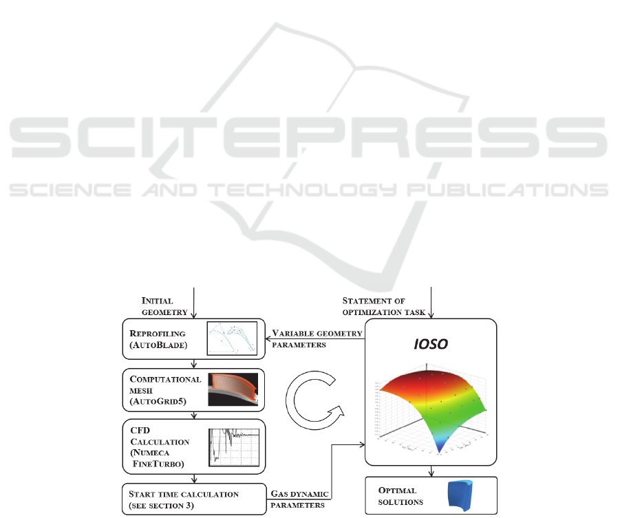
The schematic diagram of the developed ATS
optimization algorithm is shown in Figure 10. At each
optimization step, the IOSO PM optimizer generates
a vector of input parameters x
1
, x
2
, x
3
, …, x
n
. The
values of the input parameters describe the profile
geometry of the nozzle guide vanes in a parametric
form. The vector of variable parameters is transferred
to the reprofiling unit, in which the Numeca
AutoBlade program (Numeca AutoBlade, 2020)
converts the blades and saves them as geometry files
in the *.GeomTurbo format. Then, Numeca
AutoBlade 5 creates a mesh model using new blades.
At the next step, CFD calculation is performed with
the new mesh model. Processing the results of CFD
modeling is performed by a special script using
Numeca FineTurbo (Numeca FineTurbo, 2020) and
small applications from the NET Framework library.
As a result, several output files are created containing
the ATS operation parameters of interest in the text
format. Then these parameters are transferred to the
IOSO optimizer, where the results are processed and
the current optimal variant of the ATS NGV is
selected, and a new set of input parameters x
1
, x
2
, x
3
,
…, x
n
. is created. This process is iterative and runs
until the desired extremum is found, taking into
account the given constraints.
The goal of optimizing the flow part of the ATS is
to reduce the start-up time of a gas turbine engine
while reducing the torque on the turbine output shaft
(in order to increase the reliability). The presence of
two optimization criteria ensures more stable
operation of the IOSO optimizer (Kuzmenko et al.,
2007).
Based on the foregoing, the following criteria
were selected for optimization:
1) GTE start time (it must be reduced);
2) the torque on the turbine shaft (it must be
reduced).
The following parameters were set as constraints:
1) the torque at all modes must be less than the
maximum allowable value;
2) the flow parameter K
G
must be within the range
K
G
_
min
… K
G
_
max
, where the value K
G
_
min
corresponds to the minimum value of K
G
from
all operating modes of the APU, and K
G
_
max
-
to the maximum value of Kg from all operating
modes of the APU. This requirement is
necessary to fulfill the conditions for the joint
work of the APU and the ATS at all operating
modes.
The parametrization scheme for the sections of the
ATS nozzle guide vanes is shown in Figure 11.
Changing the geometry of the first nozzle guide vanes
was carried out in two control sections (hub and
shroud). Each section was described by 14
independent variables (chord, inlet and outlet design
angles, profile stagger angle, edge radii, position of
control points of the spline of the pressure side and
suction side, etc.). In total, 28 variables were used to
describe the geometry of the ATS nozzle guide vanes.
Such a statement of the optimization problem
makes it possible to find the Pareto front of optimal
solutions in which each value of the gas turbine
engine start-up time corresponds to the minimum
torque at which it can be achieved (Figure 12). Then,
in accordance with the task requirements, a variant is
selected that provides the minimum start-up time, that
can be achieved with a torque value acceptable under
the conditions of transmission strength. Obviously,
the requirement to reduce the start-up time will shift
the selected point on the Pareto front to the left as far
as possible, as much as the torque limitations allow.
Figure 10: Schematic diagram of the applied methodology for multicriteria optimization of ATS.
SIMULTECH 2020 - 10th International Conference on Simulation and Modeling Methodologies, Technologies and Applications
160
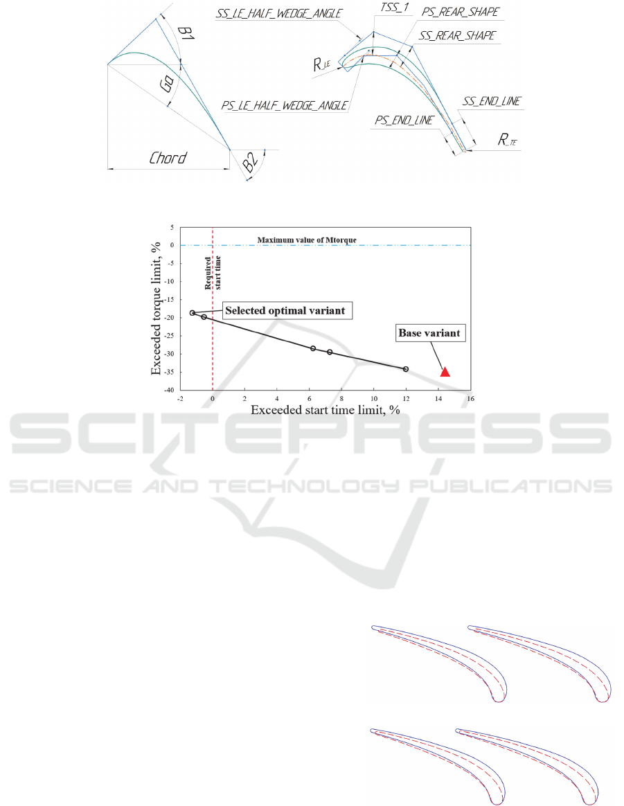
Figure 11: Parametrization scheme for the sections of the ATS nozzle guide vanes.
Figure 12: Pareto Front “Torque - Engine Start-Up Time” of the ATS variant at the most loaded operating mode.
4 OPTIMIZATION RESULTS
The optimization process was stopped after 200
calculation cycles. As a result, the Pareto front was
obtained between the values of the start-up time of the
gas turbine engine and the torque on the output shaft
of the ATS (Figure 12).
For the current problem, the case with maximum
torque and minimum start-up time is of the greatest
practical interest. The start-up time of the gas turbine
engine for the selected variant decreased by 13.7%
relative to the variant with the baseline ATS geometry
and was 1.3% less than the maximum permissible
according to the technical requirements. The
maximum torque among all the matched operating
modes of the APU did not exceed the maximum
allowable M
torque_max
by 18.5%. The value of the mass
flow parameter K
G
remained within the specified
limits K
G
_
min
...K
G
_
max
and was less than the value
K
G
_
max
by 3.8%. The latter circumstance ensured the
preservation of the coordinated work of the APU and
ATS at all operating modes. Thus, the main practical
goal of the study was achieved.
Figure 13 shows a comparison of the NGV cross-
sections of the optimized and baseline ATS variants.
The increase in the cross-sectional area and,
accordingly, the flow parameter K
G
, occurred due to
a decrease in the blade thickness, and due to a
decrease in the chord of the blade, especially in the
shroud section. Since the shape of only the stator
blades was adjusted, the strength of the most loaded
turbine elements did not change significantly.
Shroud section
Hub section
Figure 13: Blade-to-blade sections of ATS NGV: solid line
- the baseline variant; dashed line - optimized variant.
Optimization of a Single-stage Air Starter Turbine
161

5 CONCLUSIONS
This paper presents the results of the modernization
of the flow part of an existing air turbine for starting
system for application at another engine of the same
class. It was shown that the initial turbine satisfies the
requirements of working together with the APU at all
operating conditions, provides satisfaction of strength
requirements, but the start-up time when using it
exceeds by 12% the maximum time required in the
technical specifications. During the analysis, it was
found that it is necessary to increase the power of the
turbine by increasing air flow rate in order to fulfil the
requirements. Changing the parameters of the turbine
was carried out by changing the shape of the NGV.
Conducted parametric research did not allow to find
a solution. Therefore, the problem was solved using
the original algorithm using a commercial optimizer
program. As a result, a solution was found that made
it possible to find such a configuration of the turbine
flow path only by changing one element (NGV unit)
that ensures that the technical requirements in terms
of starting time are met with a margin of 2%. In this
case, the maximum torque on the turbine shaft is 18%
less than the permissible value and the conditions for
the joint operation of the turbine and the APU are
fulfilled at all operating modes.
REFERENCES
Inozemcev, A. A., Nihamkin, M. A. and Sandrackii, V. L.
2008. Fundamentals of designing aircraft engines and
power plants. Moscow: Mashinostroenie, 2008. – V.2.
– 368 p
Samara University, Access mode: https://ssau.ru/english/
Marchukov, E., Egorov, I., Popov, G., Baturin, O.,
Goriachkin, E., Novikova, Y. and Kolmakova, D. 2017.
Improving of the working process of axial compressors
of gas turbine engines by using an optimization method,
In IOP Conference Series: Materials Science and
Engineering.
Matveev, V., Baturin, O. and Popov, G. 2018. The
Optimization of Four-Stage Low Pressure Turbine with
Outlet Guide Vane. In IOP Conference Series:
Materials Science and Engineering.
United engine corporation, Access mode: https://www.
uecrus.com/eng/
Marchukov, E.Yu., Egorov, I.N. 2018. Gas Dynamic
Modernization of Axial Uncooled Turbine by Means of
CFD and Optimization Software, In IOP Conference
Series: Materials Science and Engineering.
Châtel, A., Verstraete, T., Coussement, G. 2019. Multipoint
optimization of an axial turbine cascade using a hybrid
algorithm. In Proceedings of the ASME Turbo Expo
2019: Turbomachinery Technical Conference and
Exposition, Phoenix, United States.
Asgarshamsi, A., Hajilouy-Benisi, A., Assempour, A.,
Pourfarzaneh, H. 2014. Multi-point optimization of
lean and sweep angles for stator and rotor blades of an
axial turbine. In Proceedings of the ASME Turbo Expo
2014: Turbine Technical Conference and Exposition,
Dusseldorf, Germany.
Zubanov, V. M., Matveev, V. N., Popov, G. M., Novikova,
Y. D. 2019. Maturation of an aircraft gas turbine engine
air turbo start unit on the basis of its joint action with
auxiliary power plant. In VESTNIK RGATU imeni P.A.
Solov'eva.
Popov, G., Matveev, V., Baturin, O., Novikova, J.,
Kolmakova, D. and Volkov, 2018. A. Selection of
Parameters for 3D Finite-volume Mesh for CFD
Simulation of Axial Turbines. In MATEC Web of
Conferences.
IOSO Optimization Technology. Access mode:
http://www.iosotech.com
Marchukov, E., Egorov, I., Popov, G., Baturin, O.,
Goriachkin, E. and Novikova, Y. 2019. Optimization of
a three spool axial compressor to increase the efficiency
of a gas turbine engine, In IOP Conference Series:
Materials Science and Engineering.
Marchukov, E., Egorov, I., Kretinin, G., Karonic, B. &
Fedechkin, K. 2019. Optimization of geometry blade
for modern high pressure compressor, In IOP
Conference Series: Materials Science and Engineering.
Marchukov, E.Y. and Egorov, I.N. 2018. Gas Dynamic
Modernization of Axial Uncooled Turbine by Means of
CFD and Optimization Software, In IOP Conference
Series: Materials Science and Engineering.
Marchukov, E.Y., Egorov, I., Popov, G., Salnikov, A.,
Goriachkin, E. and Kolmakova, D. 2017.
Multidisciplinary optimization of the working process
of uncooled axial turbine according to efficiency and
strength criteria. In Proceedings of the ASME Turbo
Expo.
Salnikov, A. and Danilov, M. 2019. Multidisciplinary
design optimization of a bladed disc for small-size gas-
turbine engines. In Proceedings of the ASME Turbo
Expo 2019.
Buyukli, T., Salnikov, A. and Fedorchenko, Y. 2017. High-
loaded compressor blisk-type impeller
multidisciplinary optimization. In Proceedings of the
ASME Turbo Expo 2017.
Numeca AutoBlade, Access mode: https://www.numeca.
com/product/finedesign3d
Numeca FineTurbo, Access mode: https://www.numeca.
com/product/fineturbo
Kuzmenko, M.L., Shmotin, Yu.N., Egorov, I.N. and
Fedechkin, K.S. 2007. Optimization of the gas turbine
engine parts using methods of numerical simulation. In
Proceedings of the ASME Turbo Expo 2007.
SIMULTECH 2020 - 10th International Conference on Simulation and Modeling Methodologies, Technologies and Applications
162
