
Method for Determining the Applicability of an Air Turbine for
Operation in a Gas Turbine Engine Launch System
Vasilii Zubanov
1a
, Grigorii Popov
1b
, Igor Egorov
2
, Evgenii Marchukov
2
and Yulia Novikova
1
1
Samara National Research University, Samara, Russia
2
Moscow Aviation Institute, Moscow, Russia
Keywords: Auxiliary Power Unit, Air Turbine, Joint Operation, Gas Turbine Engine, Start-up Time, Torque.
Abstract: The paper describes the methodology developed by the authors for matching the working process of the
auxiliary power unit and the air turbine used when starting the engine The need for this technique is caused
by an extremely small number of publications on this topic. The developed technique can be used to determine
the possibility of starting a gas turbine engine, as well as to calculate its time and main parameters under all
operating conditions (including in flight) and to select new auxiliary power units or an air turbine for an
existing system. The developed technique considers structural, strength, operational and other limitations. The
results were implemented as a computer program.
NOMENCLATURE
GTE - gas turbine engine
APU - auxiliary power unit
NGV - nozzle guide vane
ATS - air turbo starter
IGV - inlet guide vane
𝐾
- mass flow parameter
𝐾
- power parameter
P - pressure
T - temperature
G - mass flow rate
𝛼
- IGV stagger angle
π - pressure ratio
Δ𝐺 - losses (bleeding) of air flow in the aircraft
Δ𝑝
∗
- total pressure losses in the aircraft ducts
Δ𝑇
∗
- total temperature losses in the aircraft ducts
N - power
𝑝
- ambient pressure
𝑡
- ambient temperature
𝐽 - moment of inertia
ω - angular velocity
n - rotational speed
M - torque
- time
a
https://orcid.org/0000-0003-0737-3048
b
https://orcid.org/0000-0003-4491-1845
1 INTRODUCTION
The start of an aircraft gas turbine engine is an
important mode that largely determines the safety,
operational efficiency and reliability of the engine
and the aircraft. The gas turbine engine start-up
system includes a whole set of different devices and
units: a starter, auxiliary power unit, air and fuel
systems, automatic control system, transmission,
power supply system, ignition system, etc. For
reliable engine start-up, the operation of all the
devices must be consistent with each other.
The starting system is a “secondary” engine
system. A quick analysis of scientific and technical
publications on the topic of improving working
processes and the design of aviation gas turbine
engines showed that there are only a few works
relating to this system. However, without a starting
system, the operation of any engine will be
impossible (it simply will not “turn on”).
In the early years of jet aircrafts, the JASU or
impingement starter was often used to launch a gas
turbine engine. Today, the use of such units has been
continued in the universal UNIJASU, which are used
in the US Navy (Zoccoli and Cheeseman, 1998).
Zubanov, V., Popov, G., Egorov, I., Marchukov, E. and Novikova, Y.
Method for Determining the Applicability of an Air Turbine for Operation in a Gas Turbine Engine Launch System.
DOI: 10.5220/0009769101470154
In Proceedings of the 10th International Conference on Simulation and Modeling Methodologies, Technologies and Applications (SIMULTECH 2020), pages 147-154
ISBN: 978-989-758-444-2
Copyright
c
2020 by SCITEPRESS – Science and Technology Publications, Lda. All rights reserved
147
However, many decades ago, engineers concluded
that the most preferred engine starting system from
the efficiency, versatility and reliability of start-up
process point is an air turbine mechanically coupled
to a gas turbine rotor receiving compressed air from
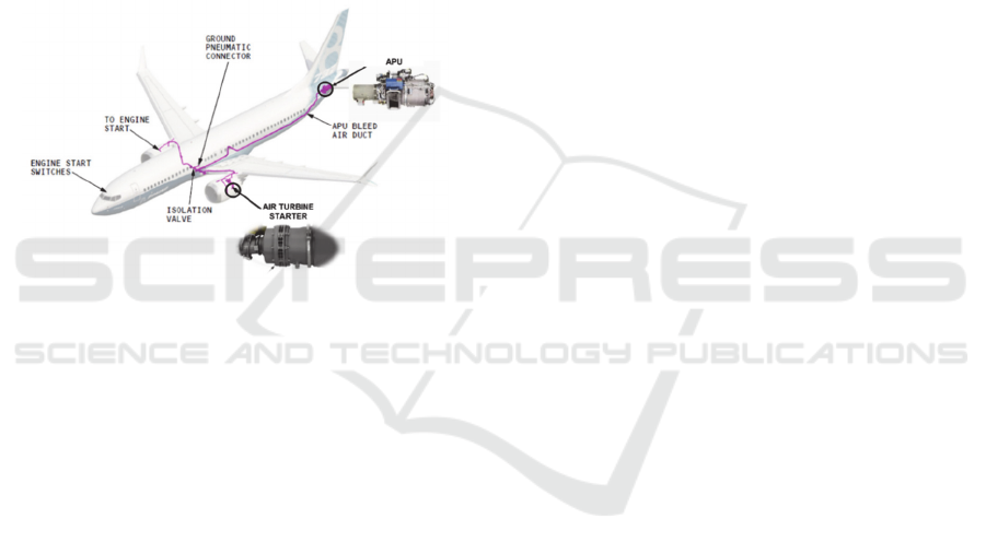
an APU compressor (Figure 1). The advantages of
such a system include high specific power, simple
design, etc. (Von Flue, 1967). Among the
shortcomings of the start systems with ATS, the
mandatory need for APU, as a source of compressed
air for turbine operation must be mentioned.
However, this drawback is not critical, since the APU
is used for many other purposes on board of the
aircraft, for example, it provides the air conditioning
system on the ground and when preparing for the
departure.
Figure 1: Schematic diagram of the launch system with
ATS.
One of the important advantages of the starting
system with ATS is the ability to ensure restarting of
the engine under any environmental conditions
(including in flight). Such an opportunity is important
not only for military engines, as it may seem at first
glance, but also for civil aviation.
The following requirements were imposed on the
launch system:
1) the operation of the ATS must be matched with
the work of the APU at all operating modes
(under various atmospheric conditions, speeds
and altitudes);
2) the GTE startup time must be minimized;
3) the torque at the output shaft must not exceed
the maximum value according to the strength
conditions of the reduction gearbox and gear
box of the engine drives.
The paper’s authors work at the Department of
Aircraft Engine Theory of Samara National Research
University (2020). They have extensive experience in
studying and improving the workflow of various
components of a gas turbine engine (Matveev et. al.,
2018). Currently, the scientific group collaborates
with various enterprises that are the part of the United
Engine Corporation (Russia) (2020). One of the
Customers set the task of assessing the feasibility of
using air turbo-starters manufactured at the enterprise
to launch a turbojet engine of the same class with a
new design.
Before solving this problem, information was
searched on the modern gas turbine engine start-up
systems and methods for increasing their
effectiveness in scientific and technical literature. The
authors were unable to find methods for solving the
problem. Moreover, an extremely small number of
publications on a topic of interest were found. If work
on optimizing the turbine workflow is found
(Marchukov et. al., 2018; Salnikov and Danilov,
2019), then not a single work has raised the issue of
matching the turbine and APU workflow. The
following is a brief overview of some of the found
articles.
A detailed simulation of the acceleration of a
turboshaft engine during a restart from “standby” to
idle mode was considered in (Ferrand et. al., 2018).
The authors examined in detail the change in the
efficiency of fuel combustion during transients in a
starting the engine, and examined the effect of heating
the engine structure during the start-up on power
losses. In their work, they focused on the processes in
the engine, because they used an electric starter in a
test unit.
Tan et. al., 2018 in their work paid attention to the
development of the control law of starting the gas
turbine engines using ATS based on its throttle
characteristics. The authors estimated the required
starter power when starting the gas turbine engine at
various altitudes and flight speeds and under various
environmental conditions. At the same time, the
authors in their work did not delve into the processes
occurring in the ATS.
The account of the processes occurring in the ATS
and its design for the engine of a large marine
ship/ground gas turbine was studied in the work of
(Park et. al., 2015). Due to the specifics of using the
ATS in terrestrial conditions, the authors considered
only one mode of ATS operation with constant inlet
parameters.
No information was found in open sources about
the start of an aircraft gas turbine engine using ATS
and their matching at all operating modes of the APU
while monitoring important operational parameters
(maximum torque and start time).
Based on the few information found, the main
goal of the work was formulated: the development of
a methodology for determining the possibility of joint
operation of an air turbo starter of a GTE with an
SIMULTECH 2020 - 10th International Conference on Simulation and Modeling Methodologies, Technologies and Applications
148
APU, the determination of the engine start time and
other system parameters in given flight conditions.
2 DETERMINATION OF THE
POSSIBILITY OF APU AND ATS
JOINT WORK
The most important key to the successful operation of
the start system is the coordination of the APU and
ATS. Indeed, if the maximum efficiency of ATS or
the required design power can only be reached at
compressed air flow rates or pressure levels
inaccessible to the APU, the required characteristics
of the whole start system will never be achieved.
For existing APU and ATS, the task of improving
start-up characteristics, for example, reducing the
start time of an aircraft gas turbine engine, can also be
set. In this case, the need to increase the power of the
ATS is implied, but at the same time, parameters must
be monitored, exceeding which can lead to the
destruction of one of the elements of the start system.
One of such parameters-indicators of dangerous loads
can be the maximum allowable torque on the output
shaft of the ATS. Its excessive value can lead, for
example, to damage of the parts of the engine
accessory-gear box.
Since the methodology for matching the operation
of the ATS and APU was not found when studying
the literature, the authors had to develop it
independently. The methodology is based on the
following assumptions:
- characteristics of the APU and ATS are
determined separately from each other. Then, they are
presented as the dependences of APU and ATS
parameters from the expansion/compression ratio of
the working fluid π;
- matching the characteristics of the APU and
ATS is carried out according to the given mass flow
parameter K
G
. It is defined as follows:
𝐾
𝐺
∙
𝑇
∗
𝑝
∗
(1)
where 𝐺
- the value of air mass flow rate
through the ATS;
𝑇
∗
- the value of the total temperature at
the ATS inlet;
𝑝
∗
- the value of the total pressure at the
ATS inlet.
The APU operation is typically described by the
following dependencies:
– dependence of the total pressure of the bleed air
from the APU 𝑝
∗
from its mass flow rate
𝐺
(𝑝
∗
𝑓
𝐺
);
– dependence of the total temperature of the bleed
air from the APU 𝑇
∗
from its mass flow rate
𝐺
(𝑇
∗
𝑓
𝐺
).
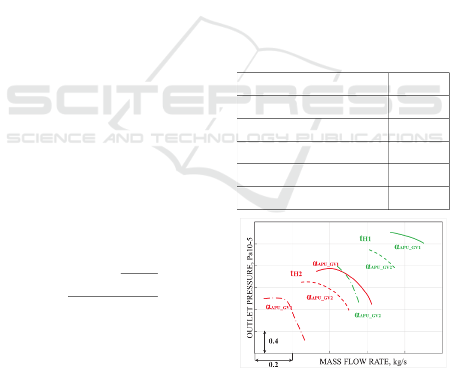
The characteristics of the APU can be presented
for several conditions of its operation, characterized
by flight altitude H, flight Mach number and
temperature of ambient (atmospheric) air 𝑡
(Figure 2
and 3) (Inozemzev et al., 2008). These characteristics
represent the dependence of pressure and temperature
in the APU pipeline under various flight conditions
(altitudes and speeds) and different positions of the
regulatory elements (for example, when changing the
stagger angles 𝛼
of the inlet guide vane). The
parameters of the APU, the characteristics of which
are shown in Figures 2 and 3 are presented in table 1.
Table 1: The main parameters of the APU.
Mass flor rate of the extracted air, kg/s 1.7
Pressure of the extracted air, atm 4.7
Temperature of the extracted air, °C 230
Electric power, kW 60
Equivalent power, kW 335
Weight, kg 190
Figure 2: Changing the pressure of the working fluid at the
APU outlet depending on the mode of its operation.
Method for Determining the Applicability of an Air Turbine for Operation in a Gas Turbine Engine Launch System
149
Figure 3: Changing the temperature of the working fluid at
the APU outlet depending on the mode of its operation.
As can be seen from Figure 4, air is taken from the
APU with the parameters 𝐺
, 𝑝
∗
,
𝑇
∗
. It goes to the ATS entrance through the
main pipelines of the aircraft. At the same time, there
are hydraulic losses and leaks in the lines, which are
characterized by the values Δ𝐺 , Δ𝑝
∗
, Δ𝑇
∗
.
Compressed air passing through the ATS turbine is
discharged into the atmosphere.
To match the operation of the ATS and APU, the
characteristics of the latter are transformed to the
form of 𝐾
𝑓𝜋
. In this case, it is
necessary to consider the interaction of the APU and
ATS. The interaction scheme between the APU and
the ATS parameters is shown in Figure 4.
The condition for the joint work of the APU and
ATS, considering Figure 4, can be represented using
the following equalities:
𝜋
𝑝
∗
𝑝
𝑝
∗
𝛥𝑝
.
∗
𝑝
𝜋
𝛥𝑝
.
∗
𝑝
(2)
𝑇
∗
∆𝑇
∗
𝑇
∗
(3)
𝐾
𝐾
(4)
The developed methodology for matching the
operation of ATS and APU considering operational
limitations can be presented as the following
sequence. The flow chart of the methodology is
shown in Figure 5.
Figure 4: The interaction scheme between the APU and the ATS parameters.
Figure 5: Brief flowchart of the developed methodology for an ATS refinement considering operating constraints.
SIMULTECH 2020 - 10th International Conference on Simulation and Modeling Methodologies, Technologies and Applications
150

Stage 1. Considering the losses on the
transmission of compressed air, the characteristics of
the APU of the initial form 𝑝
∗
𝑓
𝐺
and 𝑇
∗
𝑓
𝐺
are
transformed to the form 𝐾
𝑓𝜋
calculated by the parameters at the ATS inlet using
the following formulas:
𝐾
𝐺 APU
𝐺
APUoutlet
∆G
∙
𝑇
APUoutlet
∗
∆𝑇
∗
𝑝
APUoutle
t
∗
𝛥𝑝
ℎ𝑦𝑑𝑟.
∗
(5)
𝜋
APU
𝑝
APUoutle
t
∗
𝛥𝑝
ℎ𝑦𝑑𝑟.
∗
𝑝
ℎ
(6)
where 𝐾
– APU air mass flow parameter at
the inlet of the ATS considering losses in the
pipelines;
𝜋
– pressure ratio in the ATS determined by
the parameters of the air at the inlet to the ATS
considering losses in the pipelines;
𝐺
– the value of the mass flow rate of air taken
from the APU considering losses in the
pipelines,
:
𝐺
𝐺
∆G
(7)
𝑇
∗
– the value of the temperature of air
taken from the APU considering losses in the
pipelines, К:
𝑇
∗
𝑇
∗
∆𝑇
∗
(8)
𝑝
∗
– the value of the total pressure of air
taken from the APU considering losses in the
pipelines,
:
𝑝
∗
𝑝
∗
𝛥𝑝
.
∗
(9)
𝑝
– atmospheric pressure for altitude in standard
atmospheric conditions,
.
Stage 2. The turbine characteristics are transformed
to the relations 𝐾
𝑓𝜋
and 𝐾
𝑓𝜋
using the following formulas:
𝐾
𝐺
∙
𝑇
∗
𝑝
∗
(10)
𝐾
𝑁
∙
𝑝
∗
∙
𝑇
∗
(11)
where 𝑁
– the value of ATS power, W.
Stage 3. It is necessary to combine
characteristics ( 𝐾
𝑓
𝜋
and 𝐾
𝑓𝜋
) for the APU and ATS at one diagram,
respectively and to determine the intersection points
that will be the points that satisfy the joint operation
condition.
Stage 4. If for some operational modes no joint
points were found (no intersections of ATS and APU
characteristics), then it is necessary to adjust the
shape of ATS blades and repeat stages 1-3
determining the modified turbine characteristics
using CFD.
Step 5. The parameters of the ATS working
process are determined during its joint work with the
APU at each APU mode in the following sequence.
‒ at the intersection points of the characteristics
𝐾
𝑓𝜋
and 𝐾
𝑓𝜋
, the
parameters 𝑝
∗
, 𝑇
∗
, 𝐺
at
the output of the APU are determined;
‒ for the points of joint work of the APU and
ATS, the air parameters at the ATS inlet are
determined by the found values of the air
parameters at the APU exit (equations 7-9).
Thus, based on the intersection points of the above
characteristics, the physical characteristics of the
ATS are found when operating together with the APU
at all its modes.
Stage 6. Based on calculated parameters of the
ATS working process during its joint work with the
APU, the parameters of the start-up system (torque on
the turbine shaft and start-up time) are calculated at
each operation mode of the APU.
On the basis of the data on the torque of the output
shaft, the linear dependencies М
torque.out.sh.
=f(n
out.sh
)
(Tihonov et. al., 2001) are determined for each
operating mode:
𝑀
.
𝐴
∙𝑛
.
𝐵
(12)
Based on the found dependence, the start time of
the aircraft gas turbine engine is determined in the
future. The calculation is carried out using the
program that will be described in section 4. The
coefficient B is the maximum torque at startup, which
must be controlled.
Stage 7. If at least one of the found parameters of
the start system does not meet the technical
specifications or operational constraints, it is
necessary to adjust shape of ATS blades and repeat
stages 1-6 until the requirements are met (Figure 6).
Stage 8. If at all operating modes the limiting
quantities (first of all, the torque on the turbine shaft)
satisfy the constraints and the conditions of joint work
are fulfilled, a conclusion is made about the
possibility of coordinated operation of the APU and
ATS for the considered modes of operation of the
APU.
Method for Determining the Applicability of an Air Turbine for Operation in a Gas Turbine Engine Launch System
151
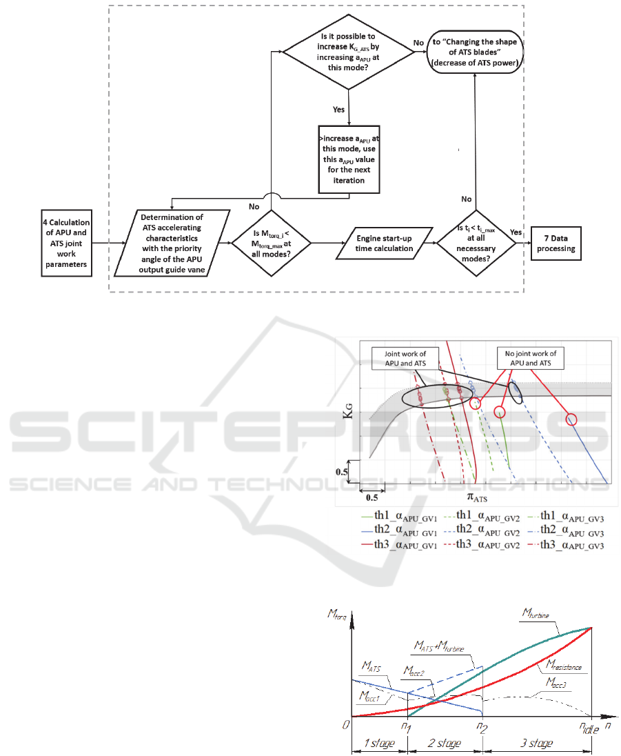
Figure 6: Flowchart of the «Checking the restrictions of startup process».
Both experimental and calculated (design)
characteristics of the APU and ATS can be used in the
developed method.
The methodology was tested in assessing the
possibility of joint operation of a two-stage air turbine
and APU as part of a turbofan engine for a civil
aviation aircraft (Figure 7). In this figure, the shaded
part of the characteristic corresponds to the operating
rotational speeds of the ATS. The intersection points
of the characteristics are the points where the
conditions for the joint operation of the APU and the
ATS (equations 5 and 6) are satisfied. An analysis of
the figure shows that when using the investigated
ATS, the coordinated work of the ATS and the APU
was not provided for all the modes of APU operation
and it is needed to change the APU, ATS or to select
new components. In addition, the torque on the ATS
shaft is greater than the maximum allowable, which
can lead to damage to the gearbox and engine drive
box.
3 CALCULATION OF THE GTE
START TIME
The spin-up of the GTE rotor at start is carried out by
the air turbine of the starter and the main turbine of
the engine, which are involved in the spin-up during
not the entire start-up period, but only at certain
stages. The process of starting the engine can be
divided into three main stages (Figure 8).
Figure 7: Combined mass flow characteristics of the APU
and ATS No. 1.
Figure 8: GTE start stages with an ATS (Alabin et. al.,
1968).
At the first stage (from the start of the launch to
the start of the active operation of the main turbine
with the rotor speed 𝑛
), the engine is spun-up only
SIMULTECH 2020 - 10th International Conference on Simulation and Modeling Methodologies, Technologies and Applications
152

by the starter. The acceleration moment of the high-
pressure rotor of the engine at this stage is:
𝑀
𝑀
𝑀
=
𝐽
𝑑𝜔
𝑑𝜏
𝐽
∙
𝜋
30
∙
𝑑𝑛
𝑑𝜏
(13)
where 𝑀
– torque on the output shaft
developed by ATS;
𝐽 — moment of inertia of the high-pressure rotor
of the engine;
ω - angular speed of rotation of the engine rotor,
s
-1
;
n – engine rotor speed, rpm;
𝑀
– torque required to rotate the
compressor, drive units and overcome friction.
At the second stage of the start-up (from 𝑛
to the
starter shutdown at the speed 𝑛
), the rotor is jointly
rotated by the turbo starter and the main turbine. In
this case, the acceleration moment of the high-
pressure rotor of the engine is calculated with the
formula:
𝑀
𝑀
𝑀
𝑀
(14)
where 𝑀
– positive torque developed by the
engine turbine.
At the third stage (after the rotational speed 𝑛
),
the air starter is switched off, and the engine rotor is
spun-up to the rotor speed at idle 𝑛
only with the
main turbine:
𝑀
𝑀
𝑀
(15)
Summarizing the above stages of starting the
engine, a generalized equation of motion of the
engine rotor at startup can be written as:
𝐽
∙
∙
∆
∆
𝑖∙𝑀
𝑀
𝑀
+∆𝑀
(16)
where 𝑖 – gear ratio to ATS in the box of units;
∆𝜏 – calculation time step, s;
∆𝑛 – change in the rotational speed of the high
pressure rotor per calculation step, rpm;
∆𝑀
– torque, considering the energy
input of the oncoming air flow at the autorotation
frequency.
The change in the rotational speed of the rotor per
calculation step, according to the generalized
equation (16), can be represented in the following
form:
∆𝑛
∆𝜏
𝐽∙
𝜋
30
𝑘
∙𝑖∙𝑀
𝑀
1 𝑘
∆𝑀
(17)
where 𝑘
– coefficient considering the change
in the starter torque during the opening of the shutter
or shutdown of the ATS;
𝑘
– coupling coefficient
between the moments of the compressor and the
turbine of the HP rotor.
The coupling coefficient between the compressor
and turbine moments changes in the range of
𝑘
0…𝑘
_
. Until there is no
combustion in the main combustion chamber,
𝑘
0. After the fuel supply, the coefficient
𝑘
increases and at a certain rotational speed of
the HP rotor 𝑛
_
, the torque of the
main turbine is compared with the compressor
resistance moment 𝑀
𝑀
. After that,
the turbine torque increases to the maximum excess
at the start-up 𝑘
_
1.
The value of the current speed is defined as
𝑛
𝑛
𝛥𝑛
. The calculation continues until the
speed of the idle mode is reached (𝑛
𝑛
.
The values of the rotation speed 𝑛
, 𝑛
and 𝑛
,
𝑘
_
depend on the characteristics of the
compressor, turbine and starter, the operation of the
combustion chamber, design and other operational
factors.
The algorithm described above was implemented
as a program for which a certificate of state
registration for a computer program No. 2019663216
was obtained (Zubanov et. al., 2019). It considers the
change in the coefficients 𝑘
and 𝑘
_
,
and 𝑀
based on the theoretical and
experimental data available to the authors. The
program supports both launch in batch mode and in
graphical mode.
The possibility of using the program in batch
mode was provided by the developer for using the
program in the automatic ATS optimization cycle.
4 CONCLUSION
This article describes the methodology for
coordinating the APU and air turbine workflow used
when starting a gas turbine engine and for calculating
the start-up time. The need for this technique is
because the authors could not find a similar one in the
available scientific and technical literature. It was
Method for Determining the Applicability of an Air Turbine for Operation in a Gas Turbine Engine Launch System
153

also found that there is an exceedingly small number
of publications devoted to the problem of launching a
gas turbine engine. No articles were found describing
the determination of the start time of a gas turbine
engine at all operating modes.
The methodology cab be used to verify the
possibility of joint functioning of the turbine and the
APU at all operating conditions, the output
parameters of the turbine, the expected time of the
spin-up of the gas turbine rotor, and the comparison
of critical system parameters with limit values. Based
on this information, a conclusion can be made about
the possibility of starting the engine in specific
conditions.
The obtained technique can be used:
‒ to assess the possibility of starting the engine
and calculating its main parameters for the
specific elements of the starting system;
‒ for the selection of APU and ATS, satisfying
the conditions of joint work and fulfilling the
specified requirements of the launch system,
including structural, operational and strength
limitations;
‒ for modernization of elements included in the
launch system in order to fulfill specified
technical requirements.
The developed techniques were implemented in
the computer programs and are ready for practical
use.
This technique is the first step in a large integrated
work carried out jointly with an industrial partner.
The obtained scientific results will be used to
optimize existing turbo starter for use on the new gas
turbine engine.
REFERENCES
Zoccoli, M. J. and Cheeseman, W. H. 1988. Development
of the Next Generation Gas Turbine Based Jet Air Start
Unit for the US Navy. In Proceedings of the ASME
1998 International Gas Turbine and Aeroengine
Congress and Exhibition. Stockholm, Sweden.
Von Flue, R.J. 1967. Pneumatic starting systems. In
Proceedings of the ASME 1967 Gas Turbine
Conference and Products Show. Houston. USA.
Inozemcev, A.A., Nihamkin, M.A. and Sandrackii, V.L.
2008. Osnovy konstruirovanija aviacionnyh dvigatelej
i jenergeticheskih ustanovok (Fundamentals of
designing aircraft engines and power plants). Moscow:
Mashinostroenie.
Aviacionnye pravila. Chast' 29. Normy letnoj godnosti
vintokrylyh apparatov transportnoj kategorii (Aviation
Rules. Part 29. Airworthiness standards of rotorcraft in
the transport category). OAO «Aviaizdat» (2003).
Samara University, Access mode: https://ssau.ru/english/
Marchukov, E., Egorov, I., Popov, G., Baturin, O.,
Goriachkin, E., Novikova, Y. and Kolmakova, D. 2017.
Improving of the working process of axial compressors
of gas turbine engines by using an optimization method.
In IOP Conference Series: Materials Science and
Engineering.
Matveev, V., Baturin, O. and Popov, G. 2018. The
Optimization of Four-Stage Low Pressure Turbine with
Outlet Guide Vane. In IOP Conference Series:
Materials Science and Engineering.
United engine corporation, Access mode:
https://www.uecrus.com/eng/
Marchukov, E. Y. and Egorov, I. N. 2018. Gas Dynamic
Modernization of Axial Uncooled Turbine by Means of
CFD and Optimization Software. In IOP Conference
Series: Materials Science and Engineering.
Salnikov, A. and Danilov, M. 2019. Multidisciplinary
design optimization of a bladed disc for small-size gas-
turbine engines. In Proceedings of the ASME Turbo
Expo 2019.
Ferrand, A., Bellenoue, M., Bertin, Y., Cirligeanu, R.,
Marconi, P. and Mercier-Calvairac, F. 2018. High
Fidelity Modeling of the Acceleration of a Turboshaft
Engine During a Restart. In Proceedings of the ASME
Turbo Expo 2018: Turbomachinery Technical
Conference and Exposition.
Tan, T., Chen, Y., Ma, X. & Zhou, C. 2018 Turbo Engine
Starting Control Law Design and Process Simulation.
In Proceedings of the 2018 9th International
Conference on Mechanical and Aerospace Engineering
(ICMAE). Budapest, Hungary;
Park, JaeHyeon, Park, Sooyoung, and Baek, JeHyun. 2015.
Design of an Air-Starter Turbine and Starting
Performance Prediction Through the Numerical
Analysis. In Proceedings of the ASME Turbo Expo
2015: Turbine Technical Conference and Exposition.
Tihonov, N. T., Musatkin, N. F. and Matveev, V. N. 2001.
Teorija lopatochnyh mashin aviacionnyh
gazoturbinnyh dvigatelej (Theory of blade machines of
aircraft gas turbine engines). Samarskij
gosudarstvennyj ajerokosmicheskij universitet im. S. P.
Koroleva.
Alabin, M. A., Kac, B. M. and Litvinov, Ju. A. 1968.
Zapusk aviacionnyh gazoturbinnyh dvigatelej (Start-up
of aircraft gas turbine engines). Moscow:
Mashinostroenie.
Zubanov, V. M., Popov, G. M., Gorjachkin, E. S.,
Novikova, Ju. D., Volkov, A. A. and Kolmakova, D. A.
2019. Program for determining the start time of a
turbomachine "Turbomachine Start Time Calculation.
Certificate of state registration of a computer program
No.2019663216.
SIMULTECH 2020 - 10th International Conference on Simulation and Modeling Methodologies, Technologies and Applications
154
