
Capturing Tracing Data Life Cycles for Supporting Traceability
Dennis Ziegenhagen
1,2
, Elke Pulvermueller
2
and Andreas Speck
1
1
Department of Computer Science, Christian-Albrechts-University Kiel, 24098 Kiel, Germany
2
Institute of Computer Science, Osnabr
¨
uck University, Postfach 4469, 49069 Osnabr
¨
uck, Germany
Keywords:
Traceability, Automation, Tracing Data Generation, Developer-tool Interaction.
Abstract:
Activities for achieving traceability in software development projects include planning, implementing, using
and maintaining a suitable strategy. Current research aims at supporting these activities by automating the
involved tasks, processes and applications. In this paper, we present a concept for developing a flexible
framework which enables the integration of respective functional modules, e.g. artifact data extractors and
trace link generators, to form traceability environments according to the project’s demands. By automating
the execution of the framework’s components and monitoring artifact-related interactions between developers
and their tools, the tracing data’s life cycle is captured and provided for further usages. This paper presents
an exemplified framework setup which is used to demonstrate the path and enrichment of tracing data along
these components. Furthermore, we discuss observations and findings which we made during defining and
realizing the example. We aim at using this information to further improve the framework in order to support
the implementation of traceability environments.
1 INTRODUCTION
Traceability applications and processes use informa-
tion about software artifacts and the relationships be-
tween them. Gathering and maintaining this data can
be done manually, but it often requires excessive ef-
forts. In the past decades, various approaches for
automating these tasks have been developed. Our
work follows this intention by supporting the automa-
tion of traceability processes by providing a flexible
infrastructure for integrating implementations along
the process chain. Examples for modular, exchange-
able parts which can be attached to the infrastructure
are artifact extractors, link recovery methods and al-
gorithms for executing analyses. Covering various
traceability processes and tasks, from data creation
to its usages, enables our infrastructure to provide
a comprehensive view on the tracing data’s life cy-
cle. The captured data includes interactions which
influence the life cycles. In order to emphasize this
main aspect of our work, we refer to this information
as dynamic tracing data. While the infrastructure is
designed to integrate current traceability functionali-
ties, its dynamic features enable further possibilities:
By directly accessing the sources of artifact modifica-
tions, especially the tools, interactions can be moni-
tored, processed and directly used in various levels of
detail. Main advantages are a) detecting relations and
contexts which can not or only hardly be extracted
from more “static” data storages, e.g. the file system,
databases or repositories, and b) providing immediate
support and assistance while artifacts are created or
modified, e.g. by recommending possible artifact re-
lationships or warning developers when modifications
result in questionable dependencies.
The overall concept, along with an example sce-
nario, has been published before (Ziegenhagen. et al.,
2019). In this paper, we present additional details
on the concept and implementation for handling trac-
ing data along the infrastructure, from its extraction
at tool interfaces to its provision for traceability ap-
plications. While the previous publication contains a
more general description of the framework and an ex-
ample, in this paper we will highlight the automatic
enrichment of captured tracing data towards dynamic
aspects. For this, the rest of the paper is organized
as follows. In section 2, we summarize general ac-
tivities for achieving traceability in software devel-
opment from a process perspective. These activities
are used for decomposing the overall process into
modular components. Section 3 describes the con-
cepts for integrating these modular building blocks
into our framework. In addition to this conceptional
description, section 4 adds details using an example.
It demonstrates the frameworks data-related function-
alities and the communication between the framework
564
Ziegenhagen, D., Pulvermueller, E. and Speck, A.
Capturing Tracing Data Life Cycles for Supporting Traceability.
DOI: 10.5220/0009581805640571
In Proceedings of the 15th International Conference on Evaluation of Novel Approaches to Software Engineering (ENASE 2020), pages 564-571
ISBN: 978-989-758-421-3
Copyright
c
2020 by SCITEPRESS – Science and Technology Publications, Lda. All rights reserved

and the modular components. We refer to the example
for presenting current findings and results of imple-
menting the framework and prototypic components in
section 5. Our work is related and compared to ex-
isting approaches and other research in section 6. Fi-
nally, section 7 contains a conclusion of the informa-
tion presented in this paper.
2 STATE-OF-THE-ART
SOFTWARE TRACEABILITY
PROCESSES
In order to outline the scope of our work, we will
briefly consider general aspects of enabling and using
traceability in software development projects. Creat-
ing and maintaining tracing data is usually guided by
specific goals and purposes. Amongst others, typi-
cal examples are analyzing the structure of a system,
determining the coverage of requirements, estimating
the impact of artifact changes, or finding unused el-
ements (Grammel and Kastenholz, 2010). Each of
these usages requires particular types and amounts of
data. For this, it has to be specified which artifacts are
to be traced, along with definitions of their relevant
relations and dependencies. While this answers the
question which data is required, the processes for cre-
ating and maintaining it have to be planned as well.
This includes decisions on which tasks are to be ex-
ecuted manually, semi-automated or fully automated.
All these initial considerations are part of a traceabil-
ity strategy that has to be planned and managed (Go-
tel et al., 2012). When the project setup meets the
defined strategy, the actual tracing data can be cre-
ated and used to fulfill the intended purpose(s). As
the project develops and evolves, more tracing data
is created. Additionally, the already existing data has
to be checked with regard to its validity, and eventu-
ally corrected or updated. This especially counts for
automatically generated data. Maro et al. refer to con-
firming wanted links and rejecting the unwanted ones
as “vetting” (Maro et al., 2018).
These four activities—defining, creating, using
and maintaining traceability—form the general state-
of-the-art procedure for realizing traceability in a
project. Amongst others, it has been described by
(Gotel et al., 2012), and (Cleland-Huang et al., 2014).
Our work is mainly aiming at supporting the imple-
mentation and execution of these activities, with a
strong focus on automation.
3 FRAMEWORK AND API
CONCEPTS
The framework’s concept and goals have been pre-
sented in previous publications, e.g. (Ziegenhagen.
et al., 2019). Here, we briefly summarize and high-
light those aspects which we consider to be helpful
for clearly presenting the following sections.
On the one hand, the framework is intended to
serve as an infrastructure and data management for
tracing data, providing interfaces for the integration
of components according to the described traceability
activities. On the other hand, it is strongly aiming at
supporting the automation of these activities and pro-
cesses. This combination of covering and automat-
ing the tracing data flow—from its generation to its
usage—enables capturing and analyzing the life cy-
cle of both, artifacts and tracing links. Aligning trace-
ability processes and applications along this flow of
data is the basis for our framework and its modular
structure. For each of these modular extension points,
individual APIs are provided, offering functionalities
for the specific purposes. The automation of compo-
nents and processes is guided by the work and tasks
of project members, e.g. developers interacting with
an IDEs. The framework’s functionalities are to be
executed without distracting the developer or disturb-
ing the actual development tasks. Thus, our work is
basically designed towards “ubiquitous traceability”
(Gotel et al., 2012).
The considered data flow starts with the assump-
tion that developers interact with various tools for cre-
ating and modifying artifacts. By connecting adapter
components to the tools’ interfaces, artifacts and re-
lated data become accessible. For example, plug-in
APIs may be used to extract artifact data and to cap-
ture user interactions. This extracted and captured
data is sent to the framework’s core component using
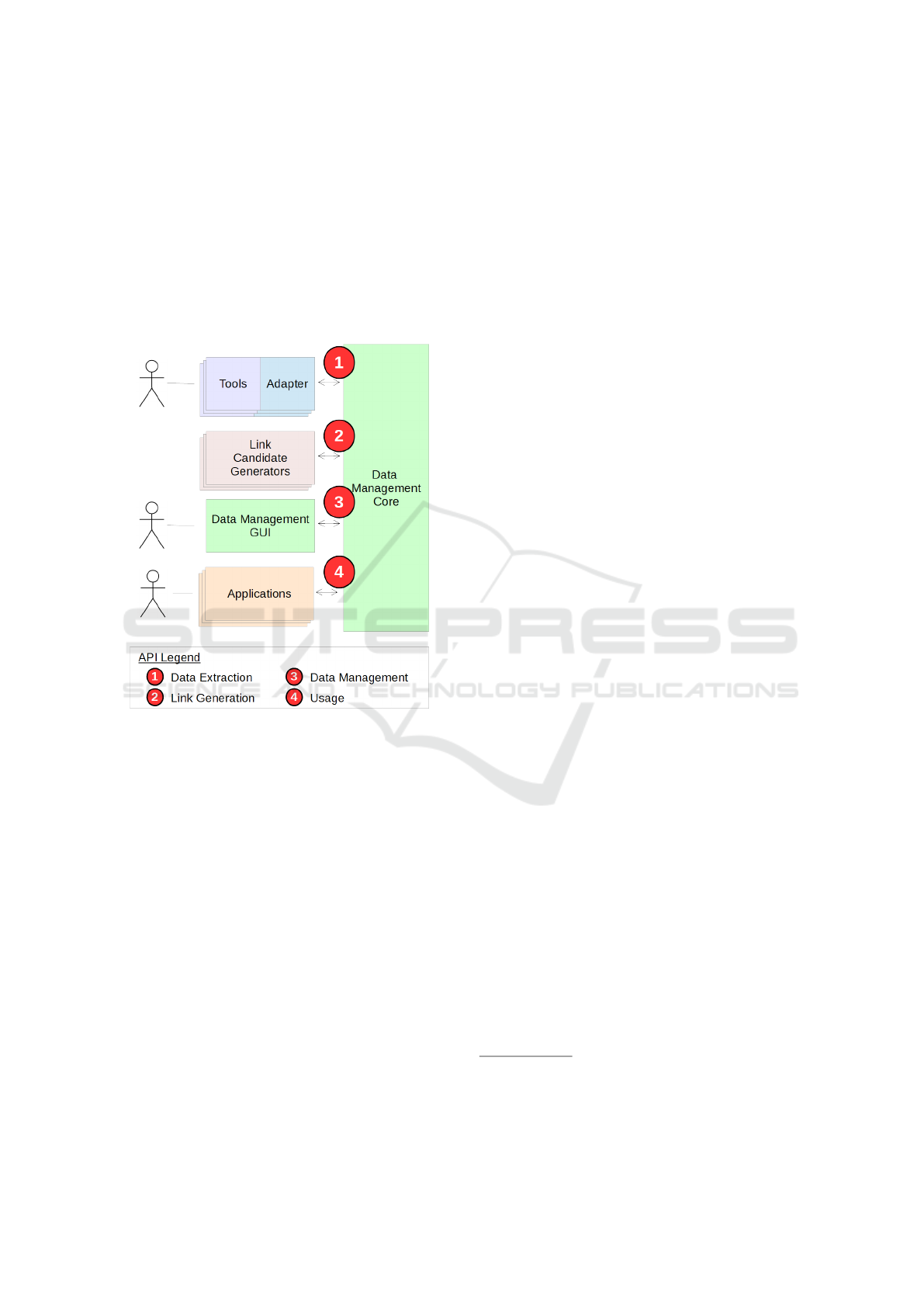
the Data Extraction API. In Figure 1, this is indicated
using red circle number ¬. When data is received at
an API, temporal information, e.g. a timestamp, is
automatically added. In the next step, link candidate
generators use the Link Generation API to receive in-
formation about relevant artifacts (cf. red circle
in Figure 1). Results of executing these components,
e.g. extracted traces, detected dependencies or other
suggested artifact links, are submitted to the frame-
work core via the Link Generation API as well. At
this point, the framework’s data base is expected to
need revision and possibly correction in order to vali-
date the automatically generated data. The respective
Data Management API which provides the unrevised
tracing data is labeled with red circle number ® in
Figure 1. This API also enables updating the state of
Capturing Tracing Data Life Cycles for Supporting Traceability
565
“revision”, e.g. marking generated tracing links ex-
plicitly as “correct”, “incorrect” or “duplicate”. Fur-
thermore, missing or additional trace links may be
submitted via this API. The framework contains an
application which enables the user to perform these
data revision tasks (cf. “Data Management GUI” in
Figure 1). Finally, the framework’s Usage API pro-
vides data and functionalities for further applications,
e.g. running analyses or creating visualizations (cf.
red circle ¯ in Figure 1).
Figure 1: Usage of the framework’s interfaces to achieve
modularity. Framework components are colored green,
while exchangeable modules are represented in different
colors. The numbers in red circles hint at interfaces which
offer particular functionalities for enabling different trace-
ability process steps.
The framework is implemented as a distributed sys-
tem. Its core functionalities are deployed on a web-
server, offering the described interfaces as RESTful
APIs. For using and adapting to them, a set of tools
and libraries is provided.
4 DYNAMIC TRACING DATA
EXAMPLE
Our research and the framework development are
guided by usage scenarios. The following example is
taken from a more comprehensive scenario, and short-
ened in order to focus on a simple data flow. By this,
the role of the different module types is exemplified.
Furthermore, relevant capabilities of the framework’s
APIs are described for demonstrating the framework-
module communication.
4.1 Tool and Framework Setup
This reduced example mainly includes two types of
artifacts: requirements and Java source code. While
the latter is directly accessed via an IDE adapter plug-
in, the requirements are only available as document
files, i.e. the tools used for editing these files are
not adapted or integrated to the framework
1
. For
such situations, the framework provides a Generic
File Adapter. This component can be configured to
monitor specific directories, including various options
for filtering files and sub-directories. Thus, monitored
files are recognized as artifacts. The default capabili-
ties for these artifact files include capturing their cre-
ation, modification and deletion, and forward these
events to the framework core (using the Data Extrac-
tion API ¬ shown in Figure 1). This initial setup
is visualized in Figure 2, containing the tools at the
top and showing the communication between compo-
nents using arrows. To expand the basic capabilities
of the Generic File Adapter, it is possible to attach
custom file handlers to it. For this, respective inter-
faces are provided, similar to the framework’s APIs.
This possibility is used in the example setup to in-
tegrate a parser for requirements documents. There-
fore, not only the document files are available as ar-
tifacts inside the framework, but also the result of
analyzing their contents, i.e. the individual require-
ments. The IDE plug-in extracts object-oriented ele-
ments, i.e. Java packages, classes and methods. Be-
sides sending this artifact information to the frame-
work’s Data Extraction API, relations between the
Java elements are also available via the tool’s API.
Thus, the adapter plug-in additionally serves as a link
generator and connects to the Link Generation API as
well. The other exemplified link generators are based
on 1) finding similarities in artifact names and 2) de-
tecting artifact-related interactions which occur close
to each other, i.e. within a configurable time window.
In the following, we refer to this component as the
“Temporal Proximity” link generator. As this paper is
about the life cycle of tracing data along the frame-
work components and interfaces, “end-user” applica-
tions which make use of the prepared tracing data pro-
vided by the Data Usage API are not included in the
reduced example.
1
Although adapting these tools would technically be
possible, this is explicitly ignored in the example scenario
in order to demonstrate different ways of accessing artifacts.
This is also discussed in section 5.
ENASE 2020 - 15th International Conference on Evaluation of Novel Approaches to Software Engineering
566
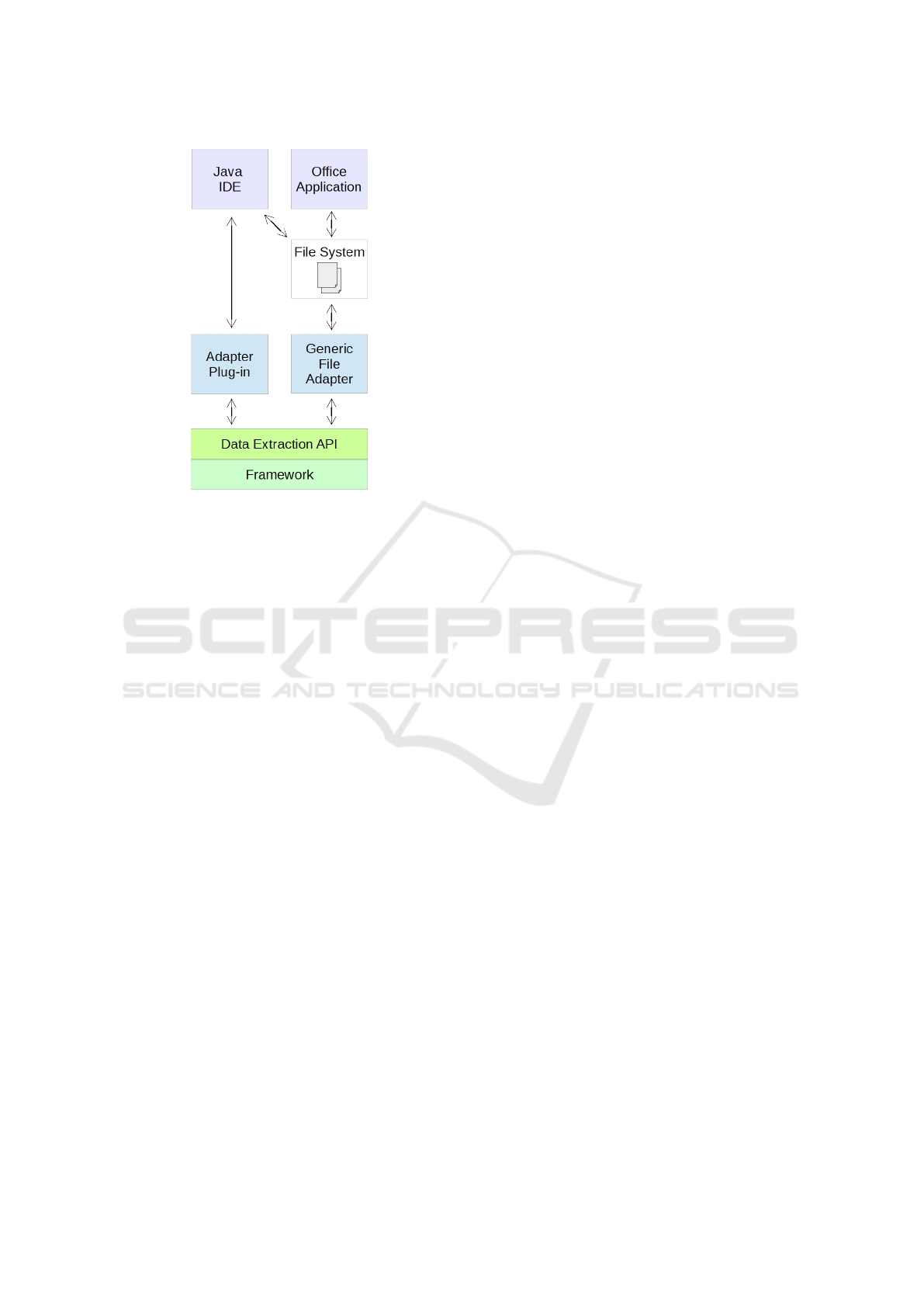
Figure 2: Example setup of tools (at the top of the figure),
the adapter components and the framework’s API for re-
ceiving extracted data.
4.2 Developer-tool Interaction and Data
Handling
The described tool and framework setup enables a
closer look at particular developer-tool interactions.
Afterwards, the corresponding data handling along
the framework infrastructure is analyzed.
The following list summarizes a sequence of
project activities using the example setup.
1. A requirements engineer adds a new item named
“User login” to an existing requirements docu-
ment.
2. The document is opened with an office application
by a developer.
3. The developer uses an IDE to write Java code for
implementing the new requirement.
4. By switching back to the office application, the
developer eventually checks the requirement de-
scription to verify his work.
5. The developer improves his code by renaming a
“Login” class to “UserLogin” for better matching
the requirement.
This excerpt of a more comprehensive development
task is kept simple and short in order to focus on
the induced stream of events and the automation of
framework components. First, activity 1 of the de-
scribed example sequence is recognized using the
Generic File Adapter. As the requirements document
already exists, the adapter sends an UPDATE notifica-
tion for this artifact to the framework using the Data
Extraction API. Furthermore, the Requirements Doc-
ument Handler is executed, which is able to locate
the changed document contents. By parsing it, the
handler identifies a new requirement and sends this
information to the framework as a CREATE event. In-
side the framework core, this information is validated
by checking if the received artifact is actually un-
known. As this is the case, the core adds the new
artifact to its database. The attached link generators
are configured to be executed when such changes of
the artifact base occur. In this step of the example,
no trace links are identified yet. The following activ-
ity 2 is not recognized in this example, because the
office application is not technically adapted. How-
ever, the interactions according to activity 3 are cap-
tured by the IDE’s adapter plug-in. As a result, re-
spective CREATE, UPDATE and DELETE events are send
to the framework, each of them relating to a specific
Java artifact, e.g. classes and methods. As the arti-
fact base changes again, the framework executes the
attached link generators. By choosing an appropriate
time window for the Temporal Proximity analysis, the
events for changing the requirements file and for edit-
ing source code occur close enough to let this compo-
nent create a trace link. It is then published at the Link
Generation API. Similar to activity 2, the interactions
related to activity 4 are not recognized. Instead, dif-
ferent effects of activity 5 can be observed. First, re-
naming the Java class is detected by the plug-in, and
corresponding events are send to the framework. Fur-
thermore, the subsequent execution of link generators
creates another trace link: The Artifact Name Similar-
ity analysis now matches the Java class “UserLogin”
and the requirement “User login” as the similarity of
these names is above a configured threshold.
5 OBERSVATIONS AND
DISCUSSION
As mentioned before, the reduced example puts the
scope on the basic data flow and usage of different
component for enabling dynamic traceability. Thus,
most modular components are simplified prototypes
for demonstrating the basic concepts. For practi-
cal framework usages in real-life applications, more
comprehensive components have to be adapted. Suit-
able approaches and solutions for the described tasks
are available (cf. related work in section 6). While
many tools, algorithms and methods for extracting ar-
tifact data, generating link candidates and using trace-
ability data exist, relatively few tools for evaluating
Capturing Tracing Data Life Cycles for Supporting Traceability
567

and improving the “correctness” of tracing data are
available. (Maro et al., 2018) found six suitable so-
lutions in scientific literature and add a custom ap-
proach based on Eclipse Capra. For this reason, the
framework contains a custom tool for managing and
maintaining the generated tracing data. As indicated
by API number ® in Figure 1, it would basically be
possible to integrate other tools for these tasks.
An advantage of the automated execution can be
found within the Temporal Proximity link generator.
Executing this component is triggered by updating the
framework’s artifact base, e.g. by receiving created
or changed artifacts at the Data Extraction API. This
link generator is able to detect temporal relations on
the fly and thus doesn’t require extensive data queries.
5.1 Amounts and Granularity of
Captured Data
In the example setup, possible influences on tracing
data caused by activities 2 and 4 are not recognized
(cf. section 4.2). While this lack of interaction mon-
itoring is intentionally included to examine its effects
and consequences, it serves as a general discussion
point as well. Developing an extension for the office
application would allow to directly access require-
ments and capture related interactions. Compared to
the basic functionalities of applying the Generic File
Adapter, this could enable the detection of more valu-
able artifact relations. For example, monitoring the
user navigating to specific file contents would cre-
ate reasonable indications for reading activities re-
lated to a particular requirement. This information
could be used in conjunction with subsequent events
from other tools to estimate relations between the re-
quirement and artifacts involved in its implementa-
tion. Capturing even more fine-grained interactions,
e.g. mouse clicks and cursor movements within docu-
ments, could further improve the aforementioned es-
timation. But this would also generate much more
data to be handled and managed by the framework and
its components, possibly leading to unnecessary com-
plexity and even performance issues. Thus, a trade-
off regarding the amount and granularity of tracing
data, the required efforts for creating it and the im-
pacts on reaching the project’s traceability goals has
to be made.
5.2 Ways of Accessing Artifacts
We considered different ways and possibilities for ac-
cessing artifacts in our approach. The two most im-
portant ones in this example are 1. utilizing tool in-
terfaces and 2. using the file system. In the following,
both are motivated and compared.
As demonstrated in the example, artifacts may
exist which are not exclusively tied to one specific
tool. Multiple IDEs are available which enable the
user to create and modify Java source code, includ-
ing additional assistance and functionalities like code
completion, syntax highlighting and verification. Fur-
thermore, this artifact type is not generally bound to
this type of development tools. Source code may
also be modified using simple text editors, or even
be the result of model-to-code transformations, e.g.
within model-driven development. Considering re-
quirements documents, the situation is quite similar.
As long as common document file formats are used,
multiple tool sets are available, e.g. Apache OpenOf-
fice, LibreOffice and Microsoft Office. In case of
proprietary requirement file formats, adapting the re-
spective tool’s interface may be preferable, if possi-
ble. For implementing our example scenario, we see
this availability of multiple tools per artifact type as a
chance to test out and examine both aforementioned
ways of accessing artifacts: Java source code via
tool interfaces, and requirements documents via the
file system. Thus, adapter plug-ins have been devel-
oped for three common Java IDEs: Eclipse, NetBeans
and IntelliJ, while requirements files are directly ac-
cessed without extending or modifying office applica-
tions. Instead, our generally applicable file monitor-
ing is used, along with a parser/handler-component
for requirements documents. Because the monitoring
implementation is based on the Java NIO.2 Watch-
Service, the adapter is compatible with various com-
mon file systems. The advantages and disadvantages
which we observed are summarized as follows:
1. Accessing Artifacts using Tool Interfaces.
• Advantages:
– Artifacts and their contents are accessible,
along with further details, e.g. meta-data and
relations to other artifacts.
– Tool functionalities may be used to gather fur-
ther information (e.g. the state of a class re-
garding syntactical correctness or compilation
results).
– Immediate capturing of user-tool interactions
and tool-internal events.
• Disadvantages:
– Effort for developing adapters is necessary.
– Expert knowledge regarding the tool’s struc-
ture, processes and its interfaces is required.
– Although relevant information may somehow
be provided by the tool, accessing it via the
available interfaces can be complex.
ENASE 2020 - 15th International Conference on Evaluation of Novel Approaches to Software Engineering
568

– In case an interface changes, e.g. when its up-
dated to a newer version, the tool adapters’
compatibility and functionality have to be
checked and possibly restored.
2. Accessing Artifact Files.
• Advantages:
– Basic monitoring capabilities are generally
available, independently from the file type.
– It is independent from which tools are used
for editing artifacts, and therefore future-proof
with regard to tool or version changes.
– Advanced artifact-specific functionalities are
possible, e.g. parsing file contents for detect-
ing more detailed changes.
• Disadvantages:
– Only the results/effects of modifications are
detectable.
– The causing interactions may only be ap-
proximately reconstructed based on detectable
modifications, e.g. the renaming of a method
which is contained in a monitored Java
file. Intermediate changes, especially undone
modifications and rejected alternative imple-
mentations, are missed.
– For implementing an advanced artifact-
specific handling, expert knowledge regarding
the file’s type, format and content is required.
This leads to additional effort and may pri-
marily result in re-implementing functionali-
ties which respective tools already provide.
Our research addresses the listed disadvantages. For
example, the APIs of common Java IDEs have been
analyzed regarding possibilities and necessary efforts
for capturing relevant artifacts and interactions. For
this, we defined simple tasks and goals, e.g. ex-
tracting and monitoring Java elements as described
in the example. We developed and compared indi-
vidual plug-ins which realize these tasks for the IDEs
Eclipse, NetBeans and IntelliJ. At first, our approach
aimed at creating an abstraction layer for tracing data-
related functions of the different plug-in APIs. During
this development, our main findings are:
• Every analyzed API is somehow able to deliver
tracing data, but with varying amounts of neces-
sary efforts and partly cumbersome implementa-
tions.
• Although the IDEs share relevant functionalities,
their APIs differ widely and are strongly based on
the underlying platform architecture (e.g. Eclipse
RCP and NetBeans Platform).
• Compared to the required efforts for develop-
ment and maintenance, only few benefits could be
gained from implementing and using the abstrac-
tion layer,
The observations discussed in this section are used
to further improve and refine our overall concept and
the framework implementation. The currently used
prototypic components enable focusing on the trac-
ing data’s life cycle for creating dynamic tracing data.
In the future, replacing these components with more
comprehensive, existing solutions could lead to new
findings and make the framework more applicable in
practice. A selection of suitable solutions is presented
in the next chapter.
6 RELATED WORK
The example scenario’s components enable a very ba-
sic handling and parsing specific requirements docu-
ments. Various proposals for more comprehensive so-
lutions have been presented. Amongst others, this is
achieved by topic modeling (Asuncion et al., 2010),
information retrieval methods (Antoniol et al., 2002),
or as part of import functionalities provided by re-
quirement tools.
Similar to our Temporal Proximity component, the
work by (Rath et al., 2018) uses temporal closeness
for finding artifact relations. Their work is limited
to commits in version control systems and entries in
issue tracking systems, but enables comprehensive
analyses of existing data. This is different to our ap-
proach, which is basically applicable for all types of
artifacts, but only handles directly monitored interac-
tions.
(Asuncion and Taylor, 2009) demonstrate captur-
ing interactions for automatic trace link generation,
including temporal relationships. Another similarity
to our approach is the use of adapters for integrat-
ing various tools as sources for interactions. Dif-
ferences are found in the importance of “historical”
tracing data, i.e. the changes and evolution of arti-
facts and traces over time: Our approach is explic-
itly including this information as “dynamic tracing
data” which enables to analyze, comprehend and re-
produce the data’s life cycle. Asuncion and Taylor do
not specify similar purposes of capturing temporal in-
formation and focus on temporal relations caused by
artifact-related interactions.
“Capra” is an Eclipse-based solution presented by
(Maro and Stegh
¨
ofer, 2016). Compared to our ap-
proach, it shares the idea of developing a flexible,
reusable and highly adaptable traceability infrastruc-
ture by offering various extension points. Differences
can be found regarding the actually exchangeable
modules and the extensible functions. Thus, the func-
Capturing Tracing Data Life Cycles for Supporting Traceability
569

tionalities which were decomposed in our approach
are not simply compatible from both, a technical and
a process perspective. Capra’s generic data model is
based on EMF and enables versatile specializations.
However, it is developed for “traditional” tracing data.
We concluded that modifying the relevant parts in or-
der to enable dynamic tracing data would require too
many changes. Yet, we will consider Capra for cre-
ating possible bridges or reusing components in our
future work.
7 CONCLUSIONS
By considering state-of-the-art traceability processes,
we developed and presented a process-oriented con-
cept for creating a modular framework for captur-
ing, managing and providing tracing data. Decom-
posing the processes enabled the design of interfaces
for flexibly integrating components according to spe-
cific tasks, e.g. artifact data extraction and trace link
generation, as well as data management and mainte-
nance. We summarized the overall concept and in-
cluded possibilities to automate the process chain.
This approach enables to focus on the data flow along
the framework, its interfaces and the integrated com-
ponents, which eventually allows to capture the trac-
ing data’s life cycle, which we refer to as dynamic
tracing data. It does not replace, but extend current
traceability methods and applications with various as-
pects of time-related interaction data, enabling to cap-
ture, analyze and use additional artifact-related infor-
mation which is usually missed by other approaches.
To sum up the most notable difference, our approach
monitors and captures information about intermedi-
ate results and modifications, which may not or only
hardly be reconstructed from the sole artifact data it-
self. Existing work already includes parts of the basic
idea, but our framework is explicitly designed and im-
plemented around it to comprehensively benefit from
dynamic data, e.g. by providing live-updates of traces
and immediate assistance during development. In this
paper, this has been demonstrated using an exam-
ple framework setup in combination with a sequence
of activities within this setup. We analyzed and de-
scribed the resulting data flow including the extrac-
tion of artifacts and the recovery of trace links. Ad-
ditionally, we highlighted the advantages of dynamic
data, i.e. capturing and analyzing temporal aspects
of artifact-related interactions. Guided by the exam-
ple, we presented and discussed observations regard-
ing the framework’s capabilities. Furthermore, advan-
tages and disadvantages of implementing components
in different ways have been presented. Because gen-
erally applicable rules for implementing traceability
are difficult to define, the discussion included possi-
ble trade-offs regarding the amount and granularity of
tracing data, the required efforts for creating it and the
impacts on reaching the project’s traceability goals.
Our research is guided by such considerations and ob-
servations, e.g. by enabling various possibilities for
creating, adjusting and specializing a traceability en-
vironment according to the individual needs.
While we have already implemented the basic in-
frastructure and the described example, we are cur-
rently extending it and include more comprehensive
scenarios. Amongst others, the goals are to exam-
ine limitations of our approach, but also to find pos-
sibilities to further benefit from the dynamic data. To
our best knowledge, it is the first framework to focus
on the described interaction-based, time-related en-
richment of tracing data. With ongoing research, we
are looking forward to find best practices for demon-
strated tasks and to simplify and assist the planning
and implementation of traceability processes.
ACKNOWLEDGEMENTS
This work is supported by the InProReg project.
InProReg is financed by Interreg 5A Deutschland-
Danmark with means from the European Regional
Development Fund.
REFERENCES
Antoniol, G., Canfora, G., Casazza, G., De Lucia, A., and
Merlo, E. (2002). Recovering traceability links be-
tween code and documentation. IEEE Transactions
on Software Engineering, 28(10):970–983.
Asuncion, H. U., Asuncion, A. U., and Taylor, R. N. (2010).
Software traceability with topic modeling. In 2010
ACM/IEEE 32nd International Conference on Soft-
ware Engineering, volume 1, pages 95–104.
Asuncion, H. U. and Taylor, R. N. (2009). Capturing cus-
tom link semantics among heterogeneous artifacts and
tools. In 2009 ICSE Workshop on Traceability in
Emerging Forms of Software Engineering, pages 1–5.
Cleland-Huang, J., Gotel, O. C. Z., Huffman Hayes, J.,
M
¨
ader, P., and Zisman, A. (2014). Software traceabil-
ity: Trends and future directions. In Proceedings of
the on Future of Software Engineering, FOSE 2014,
pages 55–69, New York, NY, USA. ACM.
Gotel, O., Cleland-Huang, J., Hayes, J. H., Zisman, A.,
Egyed, A., Gr
¨
unbacher, P., and Antoniol, G. (2012).
The quest for ubiquity: A roadmap for software and
systems traceability research. In 2012 20th IEEE
International Requirements Engineering Conference
(RE), pages 71–80.
ENASE 2020 - 15th International Conference on Evaluation of Novel Approaches to Software Engineering
570

Gotel, O., Cleland-Huang, J., Hayes, J. H., Zisman, A.,
Egyed, A., Gr
¨
unbacher, P., Dekhtyar, A., Antoniol,
G., Maletic, J., and M
¨
ader, P. (2012). Traceability
Fundamentals, pages 3–22. Springer London, Lon-
don.
Grammel, B. and Kastenholz, S. (2010). A generic trace-
ability framework for facet-based traceability data ex-
traction in model-driven software development. In
Proceedings of the 6th ECMFA Traceability Work-
shop, ECMFA-TW ’10, page 7–14, New York, NY,
USA. Association for Computing Machinery.
Maro, S. and Stegh
¨
ofer, J. (2016). Capra: A configurable
and extendable traceability management tool. In 2016
IEEE 24th International Requirements Engineering
Conference (RE), pages 407–408.
Maro, S., Stegh
¨
ofer, J., Hayes, J., Cleland-Huang, J., and
Staron, M. (2018). Vetting automatically generated
trace links: What information is useful to human ana-
lysts? In 2018 IEEE 26th International Requirements
Engineering Conference (RE), pages 52–63.
Rath, M., Rendall, J., Guo, J. L. C., Cleland-Huang, J., and
M
¨
ader, P. (2018). Traceability in the wild: Automati-
cally augmenting incomplete trace links. In Proceed-
ings of the 40th International Conference on Software
Engineering, ICSE ’18, page 834–845, New York,
NY, USA. Association for Computing Machinery.
Ziegenhagen., D., Speck., A., and Pulverm
¨
uller., E. (2019).
Using developer-tool-interactions to expand tracing
capabilities. In Proceedings of the 14th Interna-
tional Conference on Evaluation of Novel Approaches
to Software Engineering - Volume 1: ENASE, pages
518–525. INSTICC, SciTePress.
Capturing Tracing Data Life Cycles for Supporting Traceability
571
