
On the Need for a Formally Complete and Standardized Language
Mapping between C++ and UML
Johannes Trageser
1,2 a
1
Willert Software Tools GmbH, Germany
2
TU Clausthal, Germany
Keywords:
Embedded Software, Model-Driven Development (MDD), UML, C++, Tools.
Abstract:
This paper presents a vision of a well-integrated solution for implementing (embedded) software with
a model-driven approach by using UML as a semantic and conceptual extension to C++ without losing
support for established concepts, tools and libraries of C++. This requires a formally complete and
standardized language mapping between relevant and bounded subsets of C++ and UML as the foundation
for a bidirectional-translational approach between those two languages, and appropriate tooling that puts this
approach into practice. The standardized mapping is prerequisite for a model exchange among different tools.
1 INTRODUCTION
“The UML, a visual modeling language, is not
intended to be a visual programming language, in
the sense of having all the necessary visual and
semantic support to replace programming languages.
The UML is a language for visualizing, specifying,
constructing, and documenting the artifacts of a
software-intensive system, but it does draw the line
as you move toward code. Some things, like complex
branches and joins, are better expressed in a textual
programming language. The UML does have a tight
mapping to a family of OO languages so that you can
get the best of both worlds.” (OMG, 1997)
Looking at those lines from the Outside the Scope
of the UML section of the UML 1.1 specification,
it becomes clear that UML initially was neither
designed to be executable, nor as an implementation
language, but very well with a tight mapping to OO
programming-languages and a focus on “artifacts of a
software-intensive system” (OMG, 1997). Thus, the
intent was not to replace OO programming languages
but to extend them by adding new views with more
abstraction.
When Grady Booch, one of the architects of UML,
was talking about UML at the OOPSLA 1986 (Booch
et al., 1996) he pointed out that “the choice of what
models/views to create has a profound influence upon
how a problem is attacked and a solution is shaped”
a
https://orcid.org/0000-0002-6027-8501
and “no single model/view is sufficient, but complex
systems are best approached through small sets of
nearly independent models”. He also emphasized it
had been a “clear intent with UML to make certain
that all of those models are connected to reality” and
“mappings to a variety of languages” exist.
Following Booch (1996), when UML was
launched, it was challenging to balance the level of
abstraction to make UML on one hand extensible
and independent from language-specific features
but on the other hand still concrete enough
that both “forward code generation as well as
reverse-engineering” would be supported in a concept
they called “round-trip engineering” with the benefit
of “getting the best of both worlds” keeping them in a
loose synchronization.
A close mapping between UML and selected
programming languages has never been permuted as
a standard, and up till now remains unresolved.
2 BACKGROUND AND RELATED
WORK
In this work, I will take up a pragmatic and
implementation-oriented position towards modeling,
driven by real-world problems from industry projects,
using a model-driven approach with UML and
code generation to C++ for implementing embedded
systems for different domains.
540
Trageser, J.
On the Need for a Formally Complete and Standardized Language Mapping between C++ and UML.
DOI: 10.5220/0009578305400547
In Proceedings of the 15th International Conference on Evaluation of Novel Approaches to Software Engineering (ENASE 2020), pages 540-547
ISBN: 978-989-758-421-3
Copyright
c
2020 by SCITEPRESS – Science and Technology Publications, Lda. All rights reserved
2.1 Embedded Programming
Languages
Regarding Embedded Markets Studies from 2005 till
2019 (EETimes, 2005)-(EETimes, 2019) it can be
outlined that
• about 80% of the respondents use C or C++ as
programming language and
• current embedded projects often consist of
upgrades or improvements from earlier projects
with a new/upgrade ratio of 44%/56%.
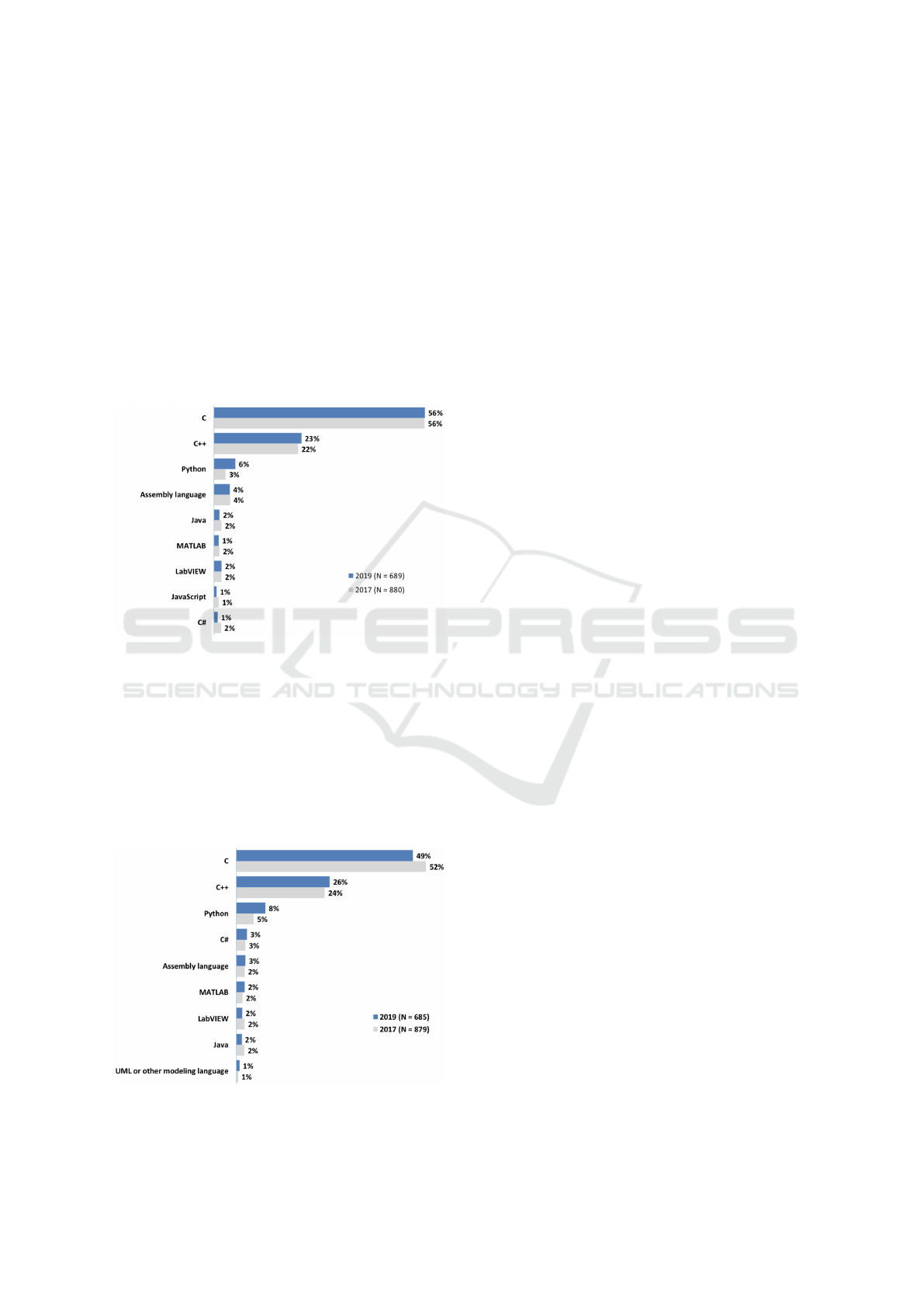
Figure 1: My current embedded project is programmed
mostly in: (EETimes, 2019).
Figures 1 and 2 are showing an extraction from
(EETimes, 2019). The percentage of C and C++ has
widely been constant over the last 15 years. This
substantiates the relevance of C and C++ being the
most important programming languages in embedded
software. C and C++ are probably not going to
disappear soon and there is a large legacy code base
existing in industrial projects.
Figure 2: My next embedded project will likely be
programmed mostly in: (EETimes, 2019).
Other languages like Java, C# and Python only
play a subordinate role as embedded programming
languages, because they only make up a small
percentage and would most likely not be found in
small embedded targets.
Figure 2, showing intended programming
languages for the next embedded project, also
introduces a new category UML or other modeling
language, confirming modeling is gaining in
importance.
With a Model-Driven-Development (MDD)
solution that builds upon C++, 70 - 80% of current
and future embedded projects could be covered.
Legacy C code could easily be integrated with C++
models and C would not have to be considered
separately, because “C++ is a direct descendant of C
that retains almost all of C as a subset.” (Stroustrup,
2020) Integration of legacy code would probably be
realised as external by only round-tripping interfaces
to the model and leaving the code as it is.
2.2 The Pragmatics of Model-Driven
Development
Bran Selic, author of the ROOM methodology and
co-chair of UML 2.0, published “The Pragmatics of
Model-Driven Development” (Selic, 2008). Although
this paper was released 12 years ago, it is still up to
date and relevant.
Following Selic (2008), in software engineering,
model-driven approaches still have to deal with
acceptance problems and rejection.
As challenges, Selic (2008) names “a conservative
mindset in both individuals and corporations” that
relies on the fact that often a large base of legacy
code has to be maintained and upgraded and building
up competency in new (model-driven) programming
technologies would require “a significant investment
in time and effort”.
“Model-driven development holds promise of
being the first true generational leap in software
development since the introduction of the compiler.
The key lies in resolving pragmatic issues related to
the artifacts and culture of previous generations of
software technologies.” (Selic, 2008)
The Quality of Models. Selic identifies five key
characteristics for the quality of models - abstraction,
understandability, accuracy, predictiveness and being
inexpensive - and declares:
“Probably the main reason why software
modeling techniques had limited success in the
past is that the models often failed to meet one or
more of the criteria just listed. In particular, the
On the Need for a Formally Complete and Standardized Language Mapping between C++ and UML
541
techniques tended to be weak in terms of accuracy
(which also meant that the models weren’t very
useful for prediction). In part, this is because
it wasn’t always clear how the concepts used
to express the models mapped to the underlying
implementation technologies such as programming
language constructs, operating system functions, and
so forth. This semantic gap was exacerbated if the
modeling language was not precisely defined, leaving
room for misinterpretation. Also, because the models
weren’t formally connected to the actual software,
there was no way of ensuring that the programmers
followed the design decisions captured in a model
during implementation. They would often change
design intent during implementation — thereby
invalidating the model. Unfortunately, because the
mapping between models and code is imprecise and
the code is difficult to comprehend, such digressions
would remain undetected and could easily lead to
downstream integration and maintenance problems.
(Changing design intent isn’t necessarily a bad thing,
but it is bad if the change goes unobserved.) Given
these difficulties, many software practitioners felt
that software models were untrustworthy, merely
adding useless overhead to their already difficult
task.” (Selic, 2008)
The Pragmatics. Selic (2008) highlights several
pragmatic issues that need to be resolved to make
MDD successful in industrial environments:
Model-level Observability. A Model needs to
obtain a level of observability that programmers are
used to. This includes model-level-debugging and
diff/merge-capabilities. (Selic, 2008)
Model Executability. A most useful model would
be executable both in “a simulation environment (for
example, on a development workstation)” and “on
the actual target platform.” (Selic, 2008)
Efficiency of Generated Code. “Current
model-to-code generation technologies can generate
code with both performance and memory efficiency
factors that are, on average, within 5 to 15 percent
(better or worse) of equivalent manually crafted
systems”, so “for the vast majority of applications,
efficiency is not an issue.” (Selic, 2008)
“Still, there might be occasional critical cases,
where manually crafted code might be necessary in
specific parts of the model. Such hot spots are often
used as an excuse to reject MDD altogether, even
when it involves a very small portion of the complete
system — the proverbial ’baby and bathwater’
scenario. A useful MDD system will allow for
seamless and overhead-free embedding of such
critical elements.” (Selic, 2008)
Integration with Legacy Environments and
Systems. “A prudent and practical way to introduce
new technology and techniques into an existing
production environment is to apply them to a
smaller-scale project such as a relatively low-profile
extension to some legacy system. This implies not
only that the new software must work within legacy
software but also that the development process and
development environment used to produce it must
be integrated into the legacy process and legacy
development environment. [...] For example, a
useful MDD tool should be able to exploit a range of
different compilers, build utilities, debuggers, code
analyzers, and software versioning control systems
rather than requiring the purchase of new ones.
Furthermore, this type of integration should work
’out of the box’ and should generally not require
custom ’glue’ code and tool expertise. [...] Last
but not least, an MDD project must be able to take
advantage of legacy code libraries and other legacy
software.” (Selic, 2008)
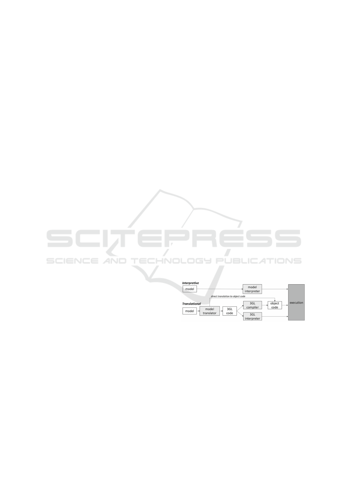
2.3 Execution of UML Models
Referring to Selic (2008) model executability is an
essential aspect of MDD. Model executability can
be achieved with an interpretive or translational
approach (Figure 3).
Figure 3: Model execution strategies (Ciccozzi et al., 2018).
In a systematic review of research and practice on
the execution of UML models, Federico Ciccozzi
ascertained: “The number of translational solutions
(70/82) clearly outnumbers the number of interpretive
(14/82) solutions” (Ciccozzi et al., 2018). Further,
out of the interpretative solutions, “none seems
to provide a solution for the execution of UML
models on the actual target platform. Instead, they
focus on higher-level execution for simulation and
model-based analysis.” (Ciccozzi et al., 2018)
Following those findings, it seems expedient to
choose a translational approach for modeling actual
production-quality software.
ENASE 2020 - 15th International Conference on Evaluation of Novel Approaches to Software Engineering
542
2.4 The UML/C++ Interrelationship
As UML models, besides the graphical notation
also require textual action language for the
implementation of actions, there are 2 possible
ways to look at the interrelationship between UML
and C++ from a UML viewpoint:
• C++ as the target language for code generation,
without constituting the action language, e.g.
Chess Project (Ciccozzi et al., 2012)
• C++ as both the target language for code
generation as well as the action language
Both approaches have their reason for being. If
the action language is independent of the target
language, this adds more abstraction and can be
useful for heterogeneous systems with different
target languages, but also has disadvantages as it
requires additional learning effort and possibly adds
restrictions in expressiveness, compared to the use of
the target language as action language. Regarding
“integration with legacy environments and systems”
(Selic, 2008) and the percentage of C and C++
as the programming language in embedded projects
(EETimes, 2019), using C++ as target and action
language with a language mapping as close to C++
as possible is therefore seen as the preferred practice.
Another way to look at the UML/C++
interrelationship is a bottom-up approach. From
this viewpoint, UML diagrams are a graphical
representation of written C++ code and UML tools
can use reverse-engineering to import C++ code as a
model and visualize it in diagrams.
Listing 1 exposes a simple example written in
C++. The final keyword used in line 6 and line 8 was
introduced with C++11.
1 c l a s s Base {
2 p u b l i c :
3 v i r t u a l v oi d f o o ( ) = 0 ;
4 } ;
5
6 c l a s s A f i n a l : p u b l i c Ba s e {
7 p u b l i c :
8 v i r t u a l i n l i n e v o i d f o o ( ) f i n a l { } ;
9 } ;
Listing 1: Final keyword sample.
Trying to create a model from this code through
reverse-engineering with the three most used UML
tools Rhapsody, Enterprise Architect and Magic
Draw, it could be detected that none of those tools
was able to execute the reverse-engineering of this
code out of the box. Without the final keywords,
the code is C++98 compliant and reverse-engineering
was straightforward with all three tools. This
indicates that UML tools have problems dealing with
up-to-date C++ standards. As this experiment only
scratches the surface, further investigations have to be
done to get a better-founded data base on the limits of
current UML modeling solutions regarding C++ code
generation capabilities.
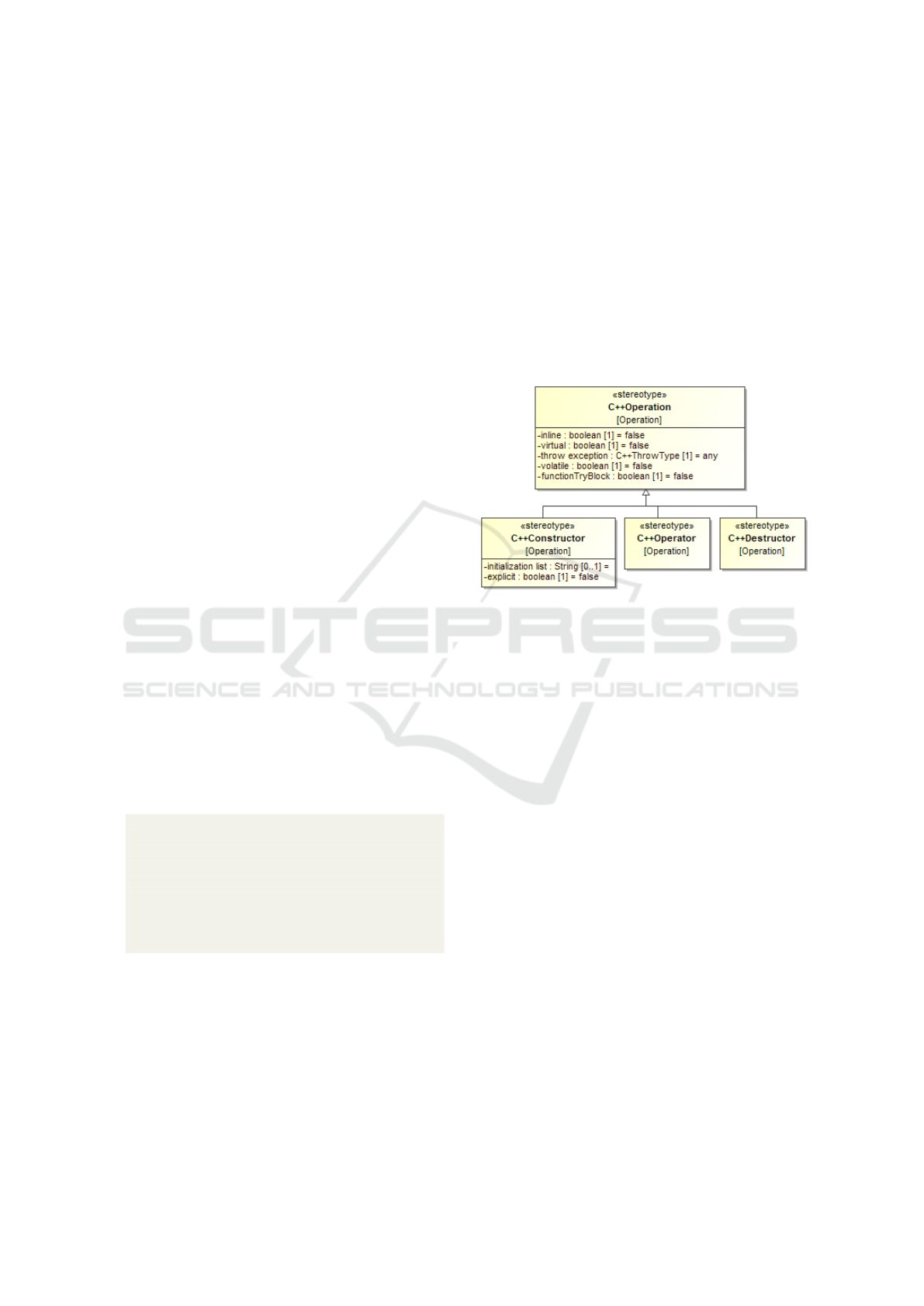
Figure 4 shows an extract of the C++ mapping to
UML for an operation that is used by Magic Draw.
This mapping is proprietary for Magic Draw and also
incomplete regarding keywords like final, override or
constexpr that are available since C++11.
Figure 4: Magic Draw C++ Mapping to UML for Operation
(NoMagic, 2020).
Also, other tools like Rhapsody and Enterprise
Architect have such proprietary mappings, but more
implicitly integrated within the tool.
This experiment substantiates the need for a
standardized UML/C++ language mapping that refers
to up-to-date C++ standards.
2.5 Research Gaps
There are several research gaps concerning the
interrelationship between UML and C++.
First of all, there is no standardized language
mapping between UML and C++ at all. UML, even
with the fUML (OMG, 2018) and Precise Semantic
Standards PSCS (OMG, 2019a) and PSSM (OMG,
2019b), still is not precise and formal enough to be
translated to C++ without a risk of misinterpretation,
acknowledging that this was never in scope of neither
pure UML nor fUML.
Furthermore, existing proposals and solutions for
model transformation or execution are often limited in
the coverage of the UML language, and “only a few
research studies provide evidence of industrial use.”
(Ciccozzi et al., 2018)
Even though publications exist for UML code
generation to C++, e.g. (J
¨
ager et al., 2016), the gaps
On the Need for a Formally Complete and Standardized Language Mapping between C++ and UML
543
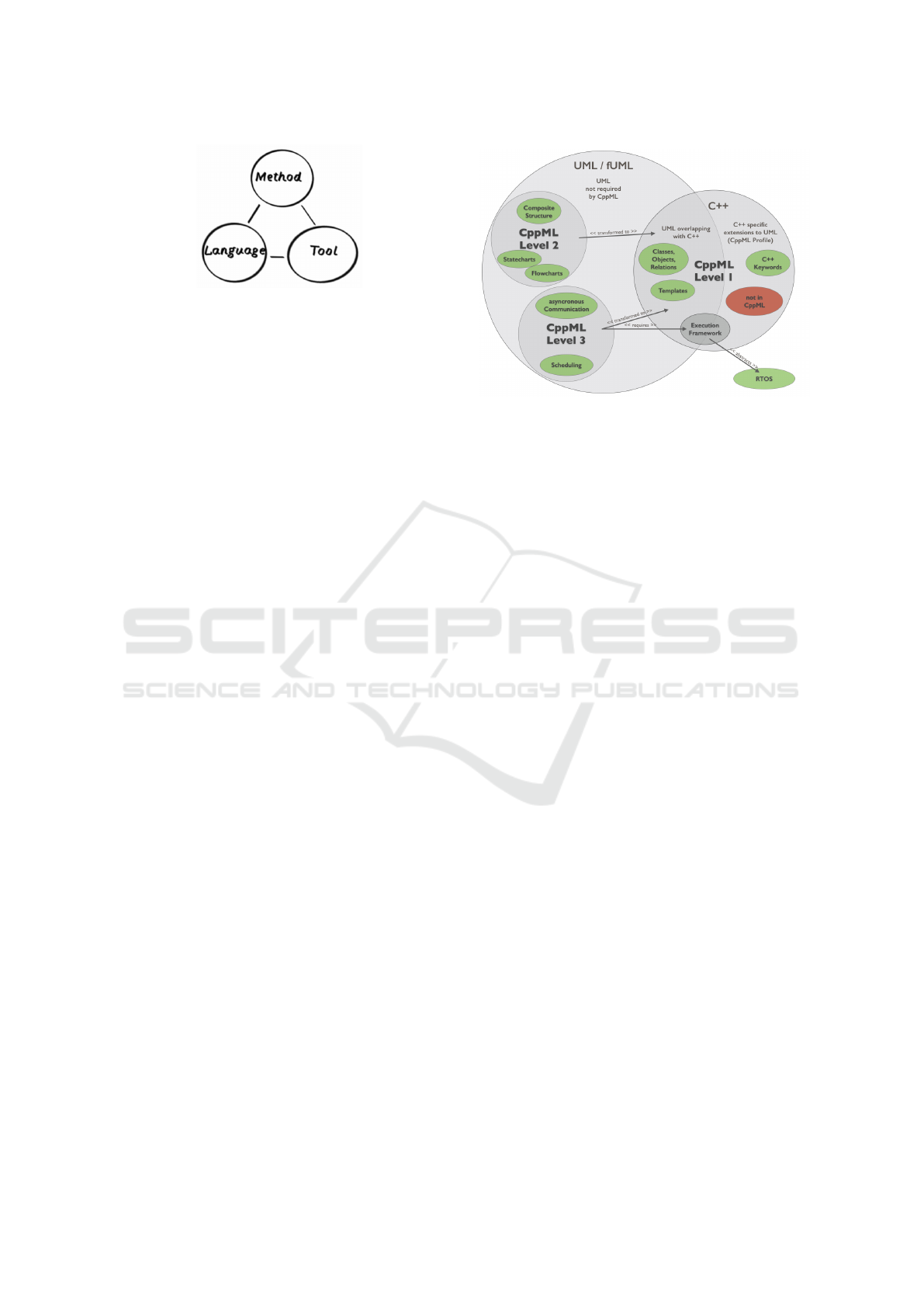
Figure 5: The Three Concerns of Modeling (Weilkiens,
2016).
regarding the UML/C++ interrelationship identified
in this paper are still unresolved. There is no
existing solution that covers all three concerns of
modeling - method, language and tooling (Figure 5).
Due to the missing standardized language mapping
between UML and C++ - or in other words, a missing
modeling language for C++ software, modeling
tool vendors introduce proprietary, non-portable
solutions, making it impossible to define a tool- and
language-independent method.
3 THE VISION - CppML
In the following sections, I will present my vision
of a well-integrated solution for implementing
(embedded) software with a model-driven approach
by using UML as a semantic and conceptual
extension to C++ without losing support for
established concepts, tools and libraries of C++.
This requires a formally complete and standardized
language mapping between relevant and bounded
subsets of C++ and UML as the foundation for
a bidirectional-translational approach between those
two languages. C++ code will be regarded as a textual
representation of the model in analogy to diagrams
being regarded as a graphical representation. The
fusion of those two languages will be introduced
as CppML (C++ Modeling Language). This vision
includes aspects of all three concerns (Figure 5): The
CppML-Profile and the transformation rules represent
the language aspect. Furthermore, also appropriate
tooling has to be available, guiding the developer
through a well-defined method with documented best
practices and restrictions.
Figure 6 displays the way to look at the UML/C++
interrelationship this work will be based on. The
CppML levels will be introduced in detail in (3.1).
The overlap between C++ and UML represents the
concepts that exist in both languages (e.g. classes,
objects, relations). Level 2 and 3, including the
overlap between UML and C++, correspond to the
scope of fUML, the executable subset of UML (e.g.
Figure 6: Overview of UML/C++ Interrelationship.
activities, state machines, signals, active classes).
The part of C++, not being available in UML, will
have to be specified as an extension for UML in a
CppML-Profile and will primarily contain modifiers,
e.g. for classes or operations like virtual, final and
constexpr that are important as an implementation
detail in C++, but are not available in UML at the
moment, neither without nor with a standardized
profile. Certainly, it will not be possible to cover
every aspect of C++ in this CppML-Profile. The
red oval in the right represents C++ features that are
not part of CppML. For example, it will be out of
scope to map every possible C++ preprocessor magic
to UML because even in C++, it would not be best
practice to use it. Also, it has to be investigated
how functional programming aspects of C++ can be
mapped to UML. CppML therefore will probably be
limited to a subset of UML and a subset of C++.
Nevertheless, those subsets have to be identified and
specified and mapped to each other as formal and as
complete as possible.
3.1 CppML Abstraction-levels
There is a large number of UML tools out there, being
able to generate code from UML models, but there
are large differences in the supported subset of UML
used for code generation and therefore the provided
level of abstraction, starting from only generating
code frames from class diagrams and ending with
a completely model-based approach including code
generation from activity diagrams, state machine
diagrams, modeling of scheduling and concurrent
behavior and generation of test code from sequence
diagrams. In this section, I will introduce a proposal
for categorizing models and tools in the completeness
of code generation to C++, regarding a meaningful
subset of UML. I will explain the different levels and
ENASE 2020 - 15th International Conference on Evaluation of Novel Approaches to Software Engineering
544

identify software developers’ needs and their benefits
on the certain levels.
The levels 1-3 refer to the CppML Levels in
Figure 6.
Level 0 - Using the Implicit Model
This level does not appear in Figure 6 because there
is no explicit model involved. But in fact, working
with a modern IDE is already kind of model-based.
The IDE builds up an internal model on top of the
source code and allows navigating, code completion,
auto-formatting and refactoring. The source code
is the primary artifact and a model representation
is only used internally. This is common practice in
software development and probably a large number
of projects work on this level.
At this level, alternate views like diagrams are only
used for specification and documentation but not in
sync with the code.
Level 1 - Basic Structural / Language Modeling
At this level, source code is not only text anymore.
Existing source code can be reverse engineered to
a model, or code frames can be generated from
architecture models. Ideally, model and source code
stay in sync after the first transformation and support
a round-trip workflow. Otherwise, they will diverge.
The source code is just a textual representation of
the model with the ability to be regenerated at every
time. This level enables additional graphical, textual
or tabular views and the possibility to link artifacts to
other engineering domains.
On this level, the broadest possible subset of the
meta-model of the programming language should be
reflected in the meta-model of the modeling language.
Otherwise, a model would be incomplete, regarding
the level of detail needed in the programming
language.
The behavior is encapsulated in operations that
are implemented as opaque behavior. On this level,
there is not yet abstraction for scheduling, nor
support for any RTOS concepts like asynchronous
communication. The scheduling is all hidden in
opaque behavior. RTOS features can only be used in
source code without abstraction.
This level adds the benefit of enabling additional
views on existing concepts but does not yet introduce
new concepts. Class diagrams are the most commonly
used diagrams at this level.
On Level 1 the gap is that UML neither represents
the complete C++ meta-model, nor a standardized
C++ profile exists for UML. So up to now, even on
this level, models become proprietary, using either a
custom C++ profile or a tool specific built-in language
extension. A standardized mapping is required here.
Creating a proposal for such a mapping will be part
of future work. As mentioned before, it will not be
possible to cover C++ completely with this profile.
It will be in focus to identify, specify and map a
meaningful subset of C++ to UML to make it more
useful for code generation.
Level 2 - Extending the Language
At this level, for the first time, new concepts and
new views are added. Concepts that are not directly
mappable to programming language features, but can
be transformed using patterns. Behavioral models
like state behavior, with the graphical representation
of state machine diagrams, are a good example.
State behavior is hard to program textually in a 3GL
without the support of a DSL like Boost SML or
a graphical semantic. UML provides a graphical
semantic for state machines, being inspired by David
Harel (Harel, 1987). Many publications have been
written on how to generate code from state machines,
and also, many tools already support generating
code from state machines. But in a systematic
review from 2012, the authors found out that “papers
published in recent years show that the problem is still
unresolved.” (Dominguez et al., 2012)
Questions that arise when adding more complex
behavior like state behavior are: How does it integrate
with existing concepts? How is it scheduled? There
are tools out there that generate execution code
for a state machine as transition function, either as
step-function or event-based, but leave it to the user
to invoke it.
On this level, there is no abstraction for
scheduling. The scheduling stays hidden in
opaque-behavior. Model elements like signals and
other asynchronous communication concepts are not
yet supported. This level only contains concepts
that can be transformed into code without using any
libraries or frameworks.
Level 3 - Entirely Model based
On this level, the whole executable subset of
UML can be transformed and synced to code.
The concepts of behavior and how behavior is
invoked (synchronous or asynchronous) are entirely
supported. This requires an execution framework
for abstracting scheduling and RTOS concepts and
managing asynchronous communication. A part of
the code will be generated from model elements by
using patterns. Those parts should normally not be
On the Need for a Formally Complete and Standardized Language Mapping between C++ and UML
545
changed in the source code. Other parts, e.g. bodies
of operations, can be edited in source code and be
round-tripped to the model. It would also be helpful
to have clear interfaces - on both model and code level
- to integrate other model-generated code, e.g. from
Matlab or from GUI tools. Additionally, also test
code can be generated from structure and sequence
diagrams.
Future work for Level 2 and 3 will be an
evaluation and specification of appropriate patterns
for transforming Level 2 and 3 concepts to prior
specified Level 1.
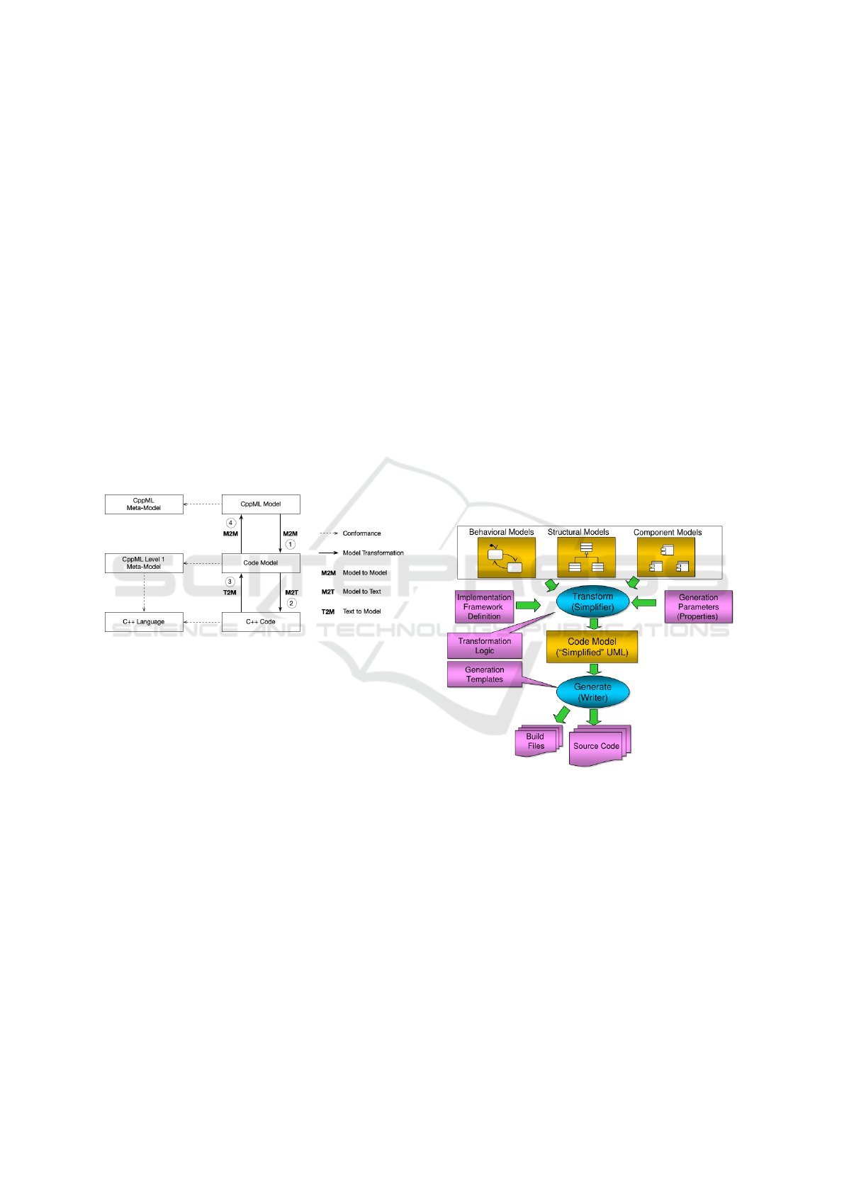
3.2 Model Transformation
The idea for the transformation from model to
source code is a two-step-bidirectional-translational
approach shown in Figure 7.
To be able to execute those transformations, the
language mapping between subsets of UML and C++
has to be formalized completely.
Figure 7: From Model to Code.
Starting from the UML Model, in step À, a
Model-to-Model (M2M) Transformation to an
intermediate Code Model is executed.
For CppML Level 1, the Code Model would be
identical with the UML model, both only containing
elements from the CppML Level 1 meta-model.
For CppML Level 2 and 3, the UML Model
will contain new concepts with new views, that have
pattern-based counterparts in the Code Model.
The use of intermediate models in the code
generation process is common practice (Ciccozzi
et al., 2018). In this proposal, the intermediate
Code Model will be a CppML Level 1 model that
conforms to the C++ meta-model, only remaining to
be serialized to text through a Model-to-Text (M2T)
Transformation in step Á.
Ideally, it would even be possible to write CppML
Level 2 or 3 patterns in code, e.g. for state machines,
and have them round-tripped in the UML model
through step  and Ã. Then the restriction, not to
modify this generated code, would be void. Looking
at C++ code from a projectional editing viewpoint
(Fowler, 2008) could be helpful to restrict the usage
of C++ to a scope that is supported by CppML.
Rhapsody Code Generation
A similar code generation concept is already realized
in the code generator of IBM Rational Rhapsody
(Figure 8). The code model is called Simplified Model
and the transformation plugin, that is responsible
for the first transformation À is called Simplifier.
What is missing here is the conformance to
standardized meta-models, which is reasoned by
suitable standardized meta-models being unavailable.
Rhapsody also offers execution frameworks for
different purposes. For small embedded targets,
Willert Embedded UML Studio (Willert, 2020)
with the RXF as Realtime eXecution Framework
is available. Many ideas of this paper arose
developing the RXF. Rhapsody, in combination with
this framework, already enables a scope of modeling
that gets close to CppML Level 3, but again as a
proprietary solution, not connected to standardized
meta-models and transformation rules.
Figure 8: Rhapsody Code Generation (IBM, 2014).
4 CONCLUSION
This paper outlined some research and specification
gaps concerning the UML/C++ interrelationship and
the language mapping between those two languages.
Additionally, the negative impact of those gaps on
tooling and portability of models is addressed. The
stocktaking of existing solutions has been started but
needs to be continued to gain a better understanding
of what is needed to really improve the situation.
Also, a vision for a solution approach is presented.
This vision needs to be elaborated in future work.
ENASE 2020 - 15th International Conference on Evaluation of Novel Approaches to Software Engineering
546

5 FUTURE WORK
In a first step, the stocktaking of existing solutions has
to continue, and it has to be discovered more detailed,
which level of CppML current UML tools support -
regarding the conceptual coverage - and if there are
best practices in the way how code is generated.
In a second step, based on the data collected in
the first step, a proposal for a standardized CppML
Level 1 has to be prepared to get a foundation for
the intermediate model. Also, aspects of projectional
editing (Fowler, 2008) will be taken into account
to find the best solution. The stereotypes, that
will extend the existing UML meta-model to the
CppML Level 1 meta-model will look similar to
the stereotypes from the Magic Draw C++ Mapping
(NoMagic, 2020) in figure 4.
In further steps, research has to be done, on how
to transform CppML Level 2 and Level 3 artifacts to
Level 1. Therefore both existing solutions in tools
(e.g. the simplifier in Rhapsody) and academic work
(e.g. (Dominguez et al., 2012)) will be taken into
account.
In parallel to the conceptual work, appropriate
tooling will be developed. A prototype tooling will
be developed based on Rhapsody and the Willert
Embedded UML Studio (Willert, 2020). This tooling
will also be evaluated in real-world industry projects.
ACKNOWLEDGEMENTS
This work was partially funded by the German
Federal Ministry of Economics and Technology
(Bundesministeriums fuer Wirtschaft und
Technologie - BMWi) within the project “Holistic
model-driven development for embedded systems”
(HolMES). The authors are responsible for the
contents of this publication.
REFERENCES
Booch, G., Jacobson, I., and Rumbaugh, J. (1996). The
unified modeling language, part i, lecture by grady
booch, ivar jacobson and james rumbaugh. OOPSLA.
Ciccozzi, F., Cicchetti, A., and Sj
¨
odin, M. (2012). Full code
generation from uml models for complex embedded
systems. In Second International Software Technology
Exchange Workshop (STEW).
Ciccozzi, F., Malavolta, I., and Selic, B. (2018). Execution
of uml models: a systematic review of research
and practice. Software & Systems Modeling,
18(3):2313–2360.
Dominguez, E., P
´
erez, B., Rubio,
´
A. L., and Zapata, M. A.
(2012). A systematic review of code generation
proposals from state machine specifications.
Information and Software Technology, 54(10):1045 –
1066.
EETimes (2005). 2005 embedded market study. Technical
report, CMP.
EETimes (2009). 2009 embedded market study. Technical
report, techinsights.
EETimes (2013). 2013 Embedded Market Study. Technical
report.
EETimes (2015). 2015 Embedded Markets Study ARM
TechCon. Technical report.
EETimes (2017). 2017 Embedded Markets Study.
Technical report.
EETimes (2019). 2019 Embedded Markets Study.
Technical report.
Fowler, M. (2008). Projectional editing. https://
martinfowler.com/bliki/ProjectionalEditing.html.
Harel, D. (1987). Statcharts - A visual Formalism for
complex Systems. pages 1 – 43.
IBM (2014). Ibm rhapsody code generation
customization. https://de.slideshare.net/gjuljo/
rhapsody-code-generation/15.
J
¨
ager, S., Maschotta, R., Jungebloud, T., Wichmann,
A., and Zimmermann, A. (2016). An EMF-like
UML Generator for C++. In Proceedings of the
4th International Conference on Model-Driven
Engineering and Software Development - Volume 1:
MODELSWARD, 4th International Conference
on Model-Driven Engineering and Software
Development, pages 309 – 316.
NoMagic (2020). Magic draw c++ mapping to uml.
https://docs.nomagic.com/pages/viewpage.action?
pageId=36315363.
OMG (1997). OMG Unified Modeling Language (OMG
UML), v1.1. Technical report.
OMG (2018). Semantics of a Foundational Subset for
Executable UML Models (fUML), v1.4.
OMG (2019a). Precise Semantics of UML Composite
Structure (PSCS), v1.2.
OMG (2019b). Precise Semantics of UML State Machines
(PSSM), v1.0.
Selic, B. (2008). The pragmatics of model-driven
development - Software, IEEE. pages 1 – 7.
Stroustrup, B. (2020). Bjarne Stroustrup FAQ. http://www.
stroustrup.com/bs faq.html#difference. Accessed:
2020-01-28.
Weilkiens, T. (2016). Variant Modeling with SysML.
MBSE4U.
Willert (2020). Willert embedded uml studio.
https://www.willert.de/software-tools/
modellgetriebene-softwareentwicklung/
willert-embedded-uml-studio/.
On the Need for a Formally Complete and Standardized Language Mapping between C++ and UML
547
