
Teaching PLC Program Organisation: How to Transfer
PLC Best Practice Experience from Industry Experts
to University Students
Ottar L. Osen
Cyber-Physical Systems Laboratory, Department of ICT and Natural Sciences (IIR),
Norwegian University of Science and Technology, Postboks 1517, NO-6025, Aalesund, Norway
Keywords:
PLC, Programming, Real-time, Industry Experience.
Abstract:
The gap between professional industry practices and academia represents a huge challenge in bringing best
practices and silent knowledge from the industry to the students. Just as having a word-processor does not
make you an author, knowing programming syntax does not make you a good programmer. In this paper I dis-
cuss how to transfer expert knowledge about PLC and real-time programming from the industry practitioners
to the students. As a special case of interest, I investigate best practices for organising PLC programs.
1 INTRODUCTION
While teaching industrial control systems, specif-
ically PLC (Programmable Logic Controller) pro-
gramming, the author has tried to find good teaching
resources on how PLCs are programmed in an effi-
cient manner that is well suited for an industrial set-
ting. There seems to be an abundance of resources
on syntax and language specifics. However, it is very
hard to find any resources that give ”best practice”
advice for PLC programming based on industrial ex-
perience.
Although syntax and language specifics are neces-
sary for a student to learn PLC programming, this is
far from sufficient in order to make the student a pro-
grammer. This is analogous to knowing how to use a
word processor does not make you a good author.
Whilst there are some good general resources on
how to bring the practitioners experience into teach-
ing (Sch
¨
on, 2017) and about best practices for general
programming (Shaw et al., 1996), they do not address
how to solve PLC and other real-time programming
challenges.
This calls for bringing practitioners experiences,
competence and knowledge to the university. How-
ever, this is a complex task and there seem to be a
lack of knowledge in the literature on how to achieve
this.
This paper attempts to address this issue by pre-
senting some advice and best practices based on the
author’s own industrial experience as a case and dis-
cusses how industrial experiences can be brought into
the students’ curriculum.
2 HOW TO PROGRAM PLCs
There are numerous sources on how PLCs work and
descriptions of syntax and programming languages.
This article focus on explaining how to utilise the
PLC in an optimum way by making sensible abstrac-
tion levels for the different actors involved in engi-
neering, construction, commissioning, maintenance
and day to day use of a PLC controlled ”machine”.
In this context ”machine” could be anything from a
simple start-stop logic for a motor that controls your
garage door to a complete control system for com-
plex systems such as a chemical plant or an offshore
oil platform. In between these extremes, you find
smaller ”machines” such as elevators, cranes, robot
cells, CNC (Computer Numerical Control) machines,
vehicles and a wide range of standard and specially
made mechatronic equipment in the processing and
manufacturing industries.
Obviously, as systems grow more complex the im-
portance of good software development standards in-
creases. However, even for small projects adherence
to the principles outlined below will have significant
cost-saving benefits.
472
Osen, O.
Teaching PLC Program Organisation: How to Transfer PLC Best Practice Experience from Industry Experts to University Students.
DOI: 10.5220/0009566004720479
In Proceedings of the 12th International Conference on Computer Supported Education (CSEDU 2020) - Volume 1, pages 472-479
ISBN: 978-989-758-417-6
Copyright
c
2020 by SCITEPRESS – Science and Technology Publications, Lda. All rights reserved

2.1 Actors and Project Phases
In the discussion below the term ”project” is used to
describe the life-cycle of a machine/plant, from engi-
neering to decommissioning. Whether the owner ac-
tually organised it as a project or not doesn’t matter
for this discussion.
In Table 1 the different project phases are outlined.
For large projects one can define even more phases
and for smaller ones some of the phases can merge
together. The breakdown in Table 1 will suffice in
order to describe the concept.
Table 1: Typical project phases.
Phase Typical activities
Concept study Idea development and feasi-
bility study
Pre-engineering Decide on important design
criteria
Engineering Detail design
Construction Building
Commissioning Testing and verification of
sub-systems
Startup Verifying total system per-
formance and debugging
Operations Day to day normal opera-
tions.
Maintenance Scheduled repairs and modi-
fications, and ad-hoc repairs
Decommissioning Deconstruction at end of
life.
In a project, there are typically a significant num-
ber of actors/roles. The number of actors and roles
depends on the size of the project. For a simple ma-
chine, there could be a single PLC with a simple panel
or GUI (Graphical User Interface), whilst on a chemi-
cal plant, there would be a large number of PLCs that
are interconnected with advanced Graphical User In-
terfaces (GUIs) and mimic panels. These larger sys-
tems are often called SCADA systems (Supervisory
Control And Data Acquisition )(Boyer, 2009). Table
2 lists some of the actors that in some way use or pro-
gram the PLC / SCADA system.
In Table 2 I have assumed that levels 1–5 are
personnel that the owner of the machine/plant has
in-house and that levels 6–9 are personnel that are
brought in to the project as needed from a PLC or
system vendor but this may also vary depending on
the size of the project, the company and its outsourc-
ing philosophies. The table is meant to be indicative
as to PLC programming competence and the essen-
tial part is to realise that there are different levels of
competence among the actors.
With reference to the project phases outlined in
Table 1 the skills and competence needed vary both
with respect to project phases and machine/plant com-
plexity/size.
In Table 3 typical PLC competence levels are out-
lined for different project phases and machine/plant
complexity/size. In this case, I have had a fairly big
project in mind and often this would be scaled down
and simplified for smaller projects.
2.2 Programmatic Consequences
In order to lower development and maintenance costs,
it is important to organise the code in such a manner
that as little PLC knowledge is needed in order to di-
agnose problems, verify signals, make small modifi-
cations and extend an existing solution. Re-use of ex-
isting code is also cost-saving and requires adherence
to good coding standards.
In the following, the main idea is that experts
make thoroughly tested ”code templates” that less
skilled personnel can use and connect to the required
inputs and outputs. This often results in a graphical
program that connects blocks to inputs and outputs
and can be maintained without extensive PLC knowl-
edge. The internal contents of the blocks will often be
quite advanced code which must, if needed, be main-
tained by personnel with extensive PLC programming
knowledge.
3 PLC PROGRAMS VS. OTHER
PROGRAMS
In the industry and in academia there is an ongoing
discussion about whether to program using a PLC, or
traditional high-level languages on industrial PCs or
controllers. Although this is a long discussion with
many elements I will outline some of the most impor-
tant aspects below.
3.1 Differences
In some ways, programming of PLCs specifically,
and real-time systems generally, differ significantly
from other types of program development. The most
prominent difference is the ”no-wait outer loop.”
A fundamental idea of real-time programs is that
Teaching PLC Program Organisation: How to Transfer PLC Best Practice Experience from Industry Experts to University Students
473
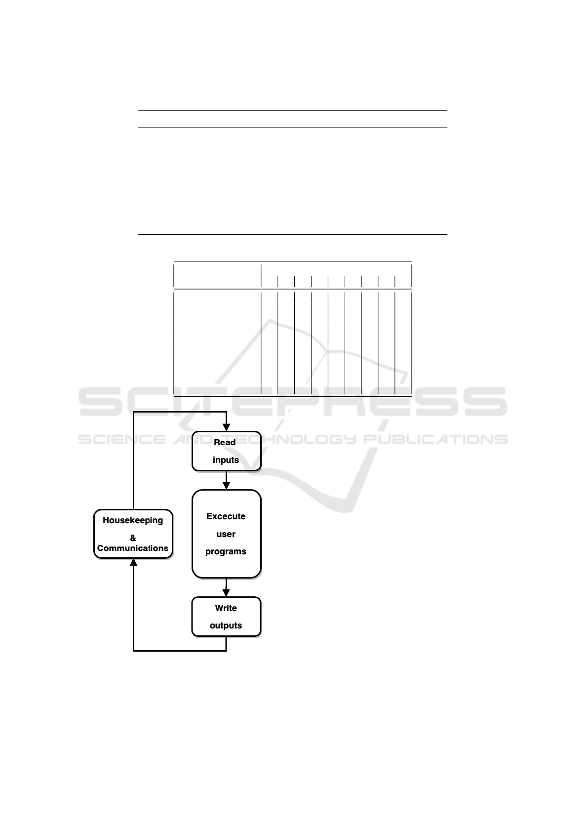
Table 2: Typical actors and knowledge.
Level Actor Knowledge
9 Vendor expert Expert PLC knowledge
8 Vendor senior engineer Very good PLC knowledge
7 Vendor system engineer Very good PLC knowledge
6 Vendor support engineer Good PLC knowledge
5 Senior system engineer Good PLC knowledge
4 System engineer Basic PLC knowledge
3 Electrical tech Electric terminations and hardware
2 Senior operator Advanced use of GUI
1 Operator Basic use of supplied GUI
Table 3: PLC competence matrix.
Phase Level
1 2 3 4 5 6 7 8 9
Concept study • ◦
Pre-engineering • •
Engineering ◦ • ◦ • ◦ • ◦ ◦
Construction ◦ • • • • ◦ ◦ • ◦
Commissioning • • • • • • • • •
Startup • • • • • • ◦
Operations • • • ◦
Maintenance • • • • ◦ ◦
Decommissioning ◦ • ◦
Figure 1: PLC execution loop.
the program should never wait in local loops for
events/inputs to occur. The program should run as fast
as possible (free-wheeling) or at a desired frequency
(cyclic), and only actions whose conditions are met
will be processed. Hence, the waiting time for the ac-
tions is spent on evaluating conditions and processing
actions whose conditions are met. This approach en-
sures that no actions are starved to death and that the
outer main loop is run at sufficient frequency. In ad-
dition, many systems support event triggers/interrupts
and some support the use of threads.
A notable feature on most PLCs is special pro-
cessing of the IO. The IO pins consist of input ports
and output ports, which may be both analogue (vary-
ing from 0–10V, say) or digital (either 0 or 24V).
The IO is processed in such a way that inputs (input
ports) are scanned into memory (variables) at the start
of the main cycle and output variables are written to
the outputs (output ports) at the end of the main cy-
cle, see Figure 1. Hence, a PLC waiting for an input
to change its value in a local loop makes no sense
since the input will not be updated before the next
start of the outer loop. This concept is of course well
known among real-time programmers and PLC pro-
grammers, but for programmers of non-real-time sys-
tems and for those who have no experience with PLCs
this may be unfamiliar and cause fatal programming
errors.
CSEDU 2020 - 12th International Conference on Computer Supported Education
474

3.2 Why Choose PLC?
As I will discuss further in the following sections the
PLC with its richness in programming languages, in-
cluding graphical ones, and ease of use enables signif-
icantly reduced costs. This is because the PLC offers
the possibility for doing simple modifications, error
corrections and fault diagnosis. In a bigger project,
the PLC approach gives reduced man-hour costs since
people at different skill levels may be used for dif-
ferent tasks and in different stages of the project,
while for traditional programming staff will need to
be highly qualified to do even minor changes. This
will be discussed more thoroughly in the next sec-
tions.
As an example of the PLC’s ease of maintenance
and diagnostics the ability to see live logic levels as
coloured lines in a logic diagram is a powerful diag-
nostics tool (see Figure 7). A graphical representation
like this which is updated live is much easier, even
for experts, to debug than the tools normally avail-
able for high-level general languages. Since PLC pro-
gramming languages are specially designed for writ-
ing real-time programs they lack most of the general
functions that we are used to in other programming
languages such as formatting of text, graphics, user
input and so on. On the other side the PLC has built-
in support for task scheduling (timed, free-wheeling
and triggered), event prioritising, state machines, par-
allel and conditional execution and so on.
In addition, due to the standardised and somewhat
limited instruction sets the chances of making serious
design mistakes are reduced. This claim is backed by
the difference in safety requirements when applying
computer-controlled systems in a process/machine.
According to IEC 61508 (IEC, 2010), a project that
uses a PLC in a process plant will typically be al-
lowed to follow the IEC 61511 (IEC, 2020) due to
its ”limited variability languages,” whereas a project
that uses a PC or a controller programmed in a tra-
ditional low or high-level language (variability lan-
guages) will have to adhere to the stricter IEC 61508.
There are of course many other pros and cons for
both approaches but these are the most important ones
with respect to the focal points for this paper. For a
detailed presentation of object-oriented control design
see Young et al. Young et al. (2001)
4 OVERALL STRUCTURE OF
PLC PROGRAMS
In the literature, there is a lot of recommendations on
how to organise computer programs in general (Shaw
et al., 1996). Many of these are also valid for PLC
programming. One might find that PLC program-
mers and programmers of high-level programming
languages tend to cluster in two groups with different
practices. Both groups could probably benefit from
studying each other’s practices.
In the following, I will address some specific rec-
ommendations for PLC programming. These are
in addition to the recommendations for general pro-
gramming and not meant to replace these, although
one should note that some of these recommendations
may be in conflict with each other. In such cases,
one must inspect the reasoning behind the recommen-
dations and weigh the advantages and disadvantages
against each other.
4.1 PLC Languages
The IEC 61131-3 standard (IEC, 2013) defines 5 lan-
guages:
• IL - Instruction List
• LD - Ladder
• FBD - Function Block Diagram
• ST - Structured Text
• SFC - Sequential Function Chart
In addition, CoDeSys and other implementations
of the standard may have additional language support
such as CoDeSys’:
• CFC - Continuous Function Chart.
Different programming languages have different
advantages and limitations. Hence, it is not a good
idea to choose a favourite and stick to it. One should
use the language best suited for the purpose.
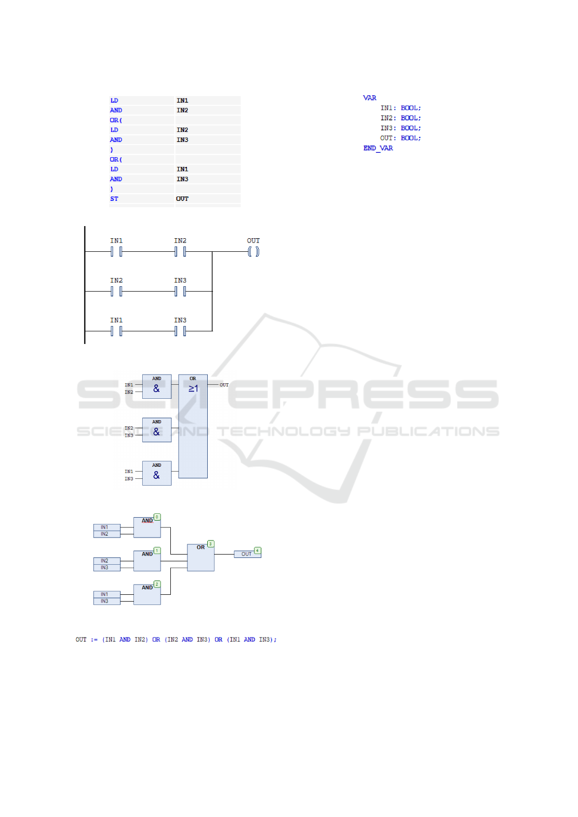
As an example, a 2 out of 3 (2oo3) voting scheme
is implemented (with identical functionality) in IL,
LD, FBD, CFC and ST for comparison as shown in
Figure 2.
Program units are called POUs (Program Organi-
sation Units), of which there are 3 main types:
• Programs
• Functions
• Function blocks
Programs are the main units, they are directly ex-
ecutable and are similar to programs in other lan-
guages. Functions are similar to functions in other
languages and they have no persistent memory. Func-
tion blocks are similar to classes in other languages,
they must be instantiated and they have persistent
memory.
Teaching PLC Program Organisation: How to Transfer PLC Best Practice Experience from Industry Experts to University Students
475
(a) Instruction List (IL).
(b) Ladder (LD).
(c) Function Block Diagram (FBD).
(d) Continuous Flow Chart (CFC).
(e) Structured Text (ST).
Figure 2: 2oo3 voting implemented in different PLC lan-
guages.
Figure 3: Variable declaration for all programs in figure 2.
A typical application setup would be programs
that read inputs, connect these to functions and func-
tion blocks and connect the outputs from the function
blocks to the PLC outputs and/or show results on a
GUI.
The term instrument is used as a general term
for equipment such as sensors and actuators. For
example, an instrument could be a temperature sen-
sor, a pressure gauge, a proximity switch, a valve, or
a pump. Typically you would group similar instru-
ments into groups and make suitable function blocks
for each group. Thereafter you would instantiate
copies of the needed function blocks for each individ-
ual instrument. For instance, 40 analogue sensors, 15
pushbuttons, and 20 indicator lamps, say, would typi-
cally require 3 different function blocks (one for each
group of instruments), with 40, 15, and 20 instantiated
copies of each, respectively. Even if the 40 analogue
sensors consisted of a mix of pressure and tempera-
ture sensors and these again have different ranges, the
function block should be parametric in order to handle
different ranges, alarm limits, or other characteristics.
Finally, there are many cases where several instru-
ments work together in what is often called ”a loop.”
As an example, a valve is typically controlled by one
output to its actuator and 2 inputs, feedbacks, indi-
cating the valve position. For example, such a valve
could be part of a tank level control loop. A tank con-
troller would typically be connected to one level sen-
sor and one valve (see Figure 4). Hence, we actually
have one loop (the valve with feedbacks) inside an-
other loop (the level control loop). The PLC program
to control this inner and outer loop is shown in Fig-
ures 5 and 6.
4.2 Which Language to Use?
The main program(s) should be organised in a suit-
able number of subprograms according to the size of
the machine or plant. These programs should be in a
graphical language such as FBD, CFC, LD or SFC.
Since most machines or plants typically will need
some kind of state machine it is advisable to employ
a master Structural Flow Chart (SFC). Even a simple
machine would typically benefit from some code run-
ning at startup in order to make sure the process is
CSEDU 2020 - 12th International Conference on Computer Supported Education
476
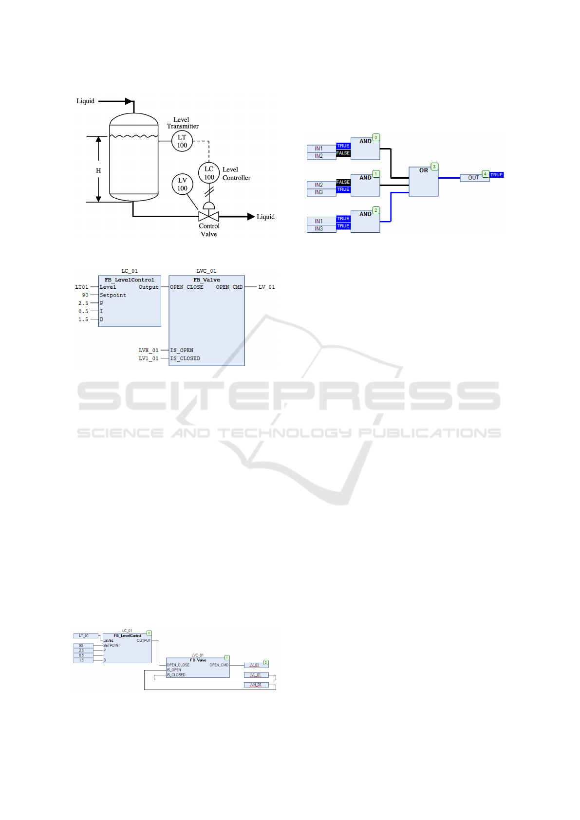
Figure 4: Tank level control example (Hughes, 2007).
Figure 5: Tank level control programmed in FBD.
ready for normal operation (calibration, making sure
mechanical parts are in the correct start position, etc.).
Furthermore, after the normal operation is complete
it is typically useful to bring the machine to a safe
condition and ready for another start (this could also
include cleaning and other operations). Hence, even
a very simple machine would have at least 3 states:
Startup, Operation, Shutdown. SFCs make debug-
ging simple since it will be possible for the service
engineer to see which state the machine is in. Inside
an SFC, in the state blocks, one may use any of the
languages and even an SFC itself.
Often, when looking for errors, the first action is
to inspect the inputs and outputs of the PLC. Some-
times it is useful to measure the inputs and the outputs
physically on the PLC whit a VAR meter, but often
it is sufficient to inspect the signals in the program.
All the graphical languages support indicating logi-
cal values with different colours etc. and variables
are readily available for inspection. Hence, debug-
Figure 6: Tank level control programmed in CFC.
ging and fault finding at the IO level becomes easy
even for non-programmers since you can graphically
see what is happening (see Figure 7).
Figure 7: Debugging using CFC.
FBD and CFC are quite similar, however CFC
gives more freedom when it comes to layout. Since
FBD and CFC resemble logic diagrams very well this
is a good way of representing logic and to show con-
nections for engineers who have some knowledge of
logic diagrams.
LD, on the other hand, resembles electrical wiring
diagrams and is well suited to show relay logic.
Hence, LD is suitable for electricians and made prob-
ably more sense historically when the PLC was seen
as a relay replacement.
ST is the best for complex tasks. However, in or-
der to keep the main program simple, it is good prac-
tice to move complex code into functions and function
blocks and keep the main program(s) in graphical lan-
guages.
Finally, IL is an assembly-like programming lan-
guage and is an unlikely candidate for anything unless
execution speed or memory limitations demand the
use of IL. In the case of automatically produced code
Est
´
evez et al. (2007) (from databases or similar), IL
would be a preferred language since its simple syntax
is easy to implement. All in all, IL is just for special
use and in the latest versions of CoDeSys the user has
to enable IL in the configuration settings, by default it
is not available.
For functions, the choice of language depends on
the problem at hand. If the problem may be easily
described in logics then FBD, CFC or LD could be
good candidates, but otherwise usually ST is the best
choice.
For function blocks, since they normally are more
complex, the most common language will be ST.
However, since function blocks often will require a
state machine, it could be useful to put the ST code
inside SFC blocks.
Teaching PLC Program Organisation: How to Transfer PLC Best Practice Experience from Industry Experts to University Students
477

5 KNOWLEDGE TRANSFER
FROM INDUSTRY TO
ACADEMIA
The challenge of transferring best practices from the
industry to the students is at least two-fold: identify-
ing the best practices and finding a suitable vessel for
transport to the minds of students.
Sch
¨
on (1987) has studied how practitioners learn.
This arises interesting questions such as how educa-
tors learn, what is the differences in information ver-
sus knowledge; education versus training; learning
versus teaching.
5.1 Identifying Best Practices
It is a common conception that industry and academia
is two worlds with (too) few connections. So how
can academics identify the best practices? Teachers
taking sabbaticals in companies would help teachers
to gain access to this ”hidden” knowledge. Since this
knowledge is hidden or implicit (Frappaolo, 2008) it
may not be easy to identify or to articulate. Some
skills are hard to put into words, such as riding a bike
or a swing. Berry (1987) states ”The fact that much
of an expert’s knowledge is implicit or tacit in nature
is a major problem for those working in the area of
knowledge elicitation.”
Another possibility is for the university to recruit
people with professional experience from the indus-
try, both in temporary and permanent positions. The
latter requires universities to change their job can-
didate evaluation procedure to include non-academic
achievements.
5.2 Vessel for Knowledge Transfer
In most subjects, the methods to achieve learning
goals vary depending on what the goals are. One pop-
ular system for this is constructive alignment (Biggs,
1996). Transferring best practice from industry to stu-
dents is not different in this respect. However, an
important keyword here is practice. Only hearing or
reading about best practices will probably be insuf-
ficient and ineffective since a lot of this knowledge
often is hidden/implicit/tacit and of a more practi-
cal and non-theoretic nature. Sch
¨
on (1987) states “I
have come to feel that [the] only learning which sig-
nificantly influences behavior is self-discovered, self-
appropriated learning.”
Guest lectures, case studies and selected industrial
challenges are ways to achieve this kind of awareness
with the students. Likewise, a selection of carefully
crafted exercises, assignments and projects that are
closely linked to an industrial setting could help illu-
minate the importance of the best practices. However,
the scale of systems found in the industry will often be
significantly bigger than what we are able to recreate
in university laboratories. Thus, it can be hard to find
means to scale exercises in a way fitting to the univer-
sity context and at the same time bringing forward the
challenges of large scale systems.
Compacting years of industrial experience into in-
formation that students can digest in a short time is
very challenging. In an industrial setting, a task can
be difficult either because it is technically challenging
or because it has a huge volume (a lot of data, equip-
ment, tools, etc., or a lot of connections). In a teach-
ing setting the former can more easily be adapted to
the students’ competency levels through making the
industrial problems the basis for exercises with suffi-
cient guidelines etc. The latter, big volume, is harder
to copy. How could we copy a big industrial setting to
the classroom and achieve anything in a short time?
Obviously, some scaling is needed. One idea could
be to carefully design a number of closely related as-
signments given to groups of students that together
formed a single large project.
Probably, in some cases we will have to accept
that there is no shortcut to gain experience, ”you have
to walk the walk”. However, in many cases, there are
ways to accelerate the process. One important tool
could be the use of hardware-in-the-loop (HIL) simu-
lation equipment (Schlager, 2008). HIL enables stu-
dents to gain experience from controlling equipment
that is normally not possible to operate on in a uni-
versity setting. The author has experimented with us-
ing HIL in PLC teaching by employing a HIL valve
simulator (Osen, 2019). A similar approach has been
used by De Farias et al. (2019) and Shiakolas and
Piyabongkarn (2003).
6 FURTHER WORK
In order to complete this study on program structure, I
am planning to write a follow-up article on how func-
tion blocks should be designed. Thereafter it could be
useful to describe good practices on how to divide a
large project plant into sections with a focus on pro-
gramming, communications, reliability and safety.
On a more general level, it would be interesting
to research in more detail different methods to trans-
fer knowledge from the industry to the students, both
from a PLC or real-time programming perspective
and a more general computer science perspective.
CSEDU 2020 - 12th International Conference on Computer Supported Education
478

7 CONCLUSIONS
There is a gap in the literature when it comes to best
practices in PLC and real-time programming. In this
paper, I have investigated the case of PLC program
organisation. This illustrates the kind of information
that is typically acquired at the workplace and often
after a significant time. The challenge is how to relay
this information to the students. Below are some take-
home messages from this case.
In order to reduce development and maintenance
costs, it is important to be able to re-use code and that
troubleshooting and maintenance can be done without
the need of experts. This can be achieved by follow-
ing these guidelines:
• Divide the program into subprograms dependant
of the size of the project.
• Make the main programs simple and easy to main-
tain.
• Use a graphical program for the main program
where inputs and outputs are connected to func-
tion blocks.
• Make the main program well suited for trou-
bleshooting.
• Use a graphical program wherever possible (sim-
ple programs and logical problems.
• Respect the real-time properties and avoid internal
loops- Don’t use IL unless absolutely necessary.
• Don’t use LD unless the program needs to be
maintained by electricians without much knowl-
edge of logic diagrams.
• Make function blocks that have parameters to sup-
port different uses.
• Put complex code and hard to maintain code in
function blocks.
ACKNOWLEDGEMENTS
The CPS Lab is grateful for the financial support pro-
vided by NTNU Excited SFU, a Norwegian Centre
for Excellent IT Education.
I also wish to thank my fellow colleague, Robin T.
Bye, for his contributions to this paper.
REFERENCES
Berry, D. C. (1987). The problem of implicit knowledge.
Expert systems, 4(3):144–151.
Biggs, J. (1996). Enhancing teaching through constructive
alignment. Higher Education, 32:347–364.
Boyer, S. A. (2009). SCADA: supervisory control and data
acquisition. International Society of Automation.
De Farias, A. B. C., Rodrigues, R. S., Murilo, A., Lopes,
R. V., and Avila, S. (2019). Low-cost hardware-in-the-
loop platform for embedded control strategies simula-
tion. IEEE Access, 7:111499–111512.
Est
´
evez, E., Marcos, M., and Orive, D. (2007). Au-
tomatic generation of plc automation projects from
component-based models. The International Jour-
nal of Advanced Manufacturing Technology, 35(5-
6):527–540.
Frappaolo, C. (2008). Implicit knowledge. Knowledge
Management Research & Practice, 6(1):23–25.
Hughes, T. A. (2007). Measurement and control basics.
IEC (2010). International Standard: IEC 61508:2010
Functional safety of electrical/electronic/
programmable electronic safety-related systems.
IEC—International Electrotechnical Commission,
IEC, Geneva, Switzerland.
IEC (2013). International Standard: IEC 61131-3:2013
Programmable controllers - Part 3: Programming
languages. IEC—International Electrotechnical Com-
mission, IEC, Geneva, Switzerland.
IEC (2020). International Standard: IEC 61511:2020
Functional safety - Safety instrumented systems for
the process industry sector. IEC—International Elec-
trotechnical Commission, IEC, Geneva, Switzerland.
Osen, O. L. (2019). On the use of hardware-in-
the-loop for teaching automation engineering. In
2019 IEEE Global Engineering Education Confer-
ence (EDUCON), pages 1308–1315. IEEE.
Schlager, M. (2008). Hardware-in-the-Loop Simulation.
VDM Verlag.
Sch
¨
on, D. A. (1987). Educating the reflective practitioner.
Sch
¨
on, D. A. (2017). The reflective practitioner: How pro-
fessionals think in action. Routledge.
Shaw, M., Garlan, D., et al. (1996). Software architecture,
volume 101. prentice Hall Englewood Cliffs.
Shiakolas, P. S. and Piyabongkarn, D. (2003). Development
of a real-time digital control system with a hardware-
in-the-loop magnetic levitation device for reinforce-
ment of controls education. IEEE Transactions on Ed-
ucation, 46(1):79–87.
Young, K., Piggin, R., and Rachitrangsan, P. (2001). An
object-oriented approach to an agile manufacturing
control system design. The International Journal
of Advanced Manufacturing Technology, 17(11):850–
859.
Teaching PLC Program Organisation: How to Transfer PLC Best Practice Experience from Industry Experts to University Students
479
