
Automated End-to-End Timing Analysis of AUTOSAR-based Causal
Event Chains
Padma Iyenghar
a
, Lars Huning and Elke Pulvermueller
Research Group Software Engineering, University of Osnabrueck, Germany
Keywords:
Unified Modeling Language, End-to-End Timing Analysis, AUTOSAR, Event Chains, Embedded
Automation.
Abstract:
Reflecting the ever-increasing complexity of automotive embedded systems and their stringent timing require-
ments, a significant level of automated tooling is imperative to enhance software quality. In this context, though
AUTOSAR-based systems are nowadays more often developed using powerful Unified Modeling Language
(UML) tools, there is a lack of an integrated approach and automated tooling for validation of timing proper-
ties. Addressing this aspect, a systematic software engineering and automation approach for timing analysis
of AUTOSAR-based systems, already early in the design stages, in state-of-the-practice timing analysis tools
is presented. A specific example of a widely used timing analysis measure for automotive systems namely,
end-to-end delay analysis is described with the help of an AUTOSAR-based causal event chain example. The
practical relevance of the approach is demonstrated by evaluating it in an elaborate automotive case study.
1 INTRODUCTION
AUtomotive Open System ARchitecture (AU-
TOSAR) is already a de facto industry standard
for the design and implementation of software for
automotive applications. Further, development of
AUTOSAR-based embedded systems using Uni-
fied Modeling Language (UML) tools is gaining
significant attention in the automotive industry.
In automotive embedded architectures, many
functions have timing constraints for performance
guarantees. Often, such systems are modeled with
task chains, which consists of a number of tasks that
are in a sequence and have a common ancestor. The
timing behavior of the task chain is determined by cal-
culating its end-to-end response time/delay. The end-
to-end delay of a task chain is defined as the amount
of time elapsed between the arrival of an event at the
first task and the production of the response by the
last task in the chain (Mubeen et al., 2019). In order
to perform the timing analysis of such a system, its
end-to-end timing analysis model with timing proper-
ties, should be available. Based on this information,
timing analysis in state-of-the-practice tools such as
SymTA/S (Henia et al., 2005), can predict the execu-
tion behavior of the system with respect to end-to-end
a
https://orcid.org/0000-0002-1765-3695
timing. This is among the most critical and widely
used performance guarantee measure in automotive
embedded systems.
In AUTOSAR-based systems, an event chain,
with an end-to-end timing constraint, describes the
causal order for a set of functionally dependent tim-
ing events (AUTOSAR, 2017). Thus, incorporating
an early, Automated End-to-End Timing Analysis of
AUTOSAR-based Causal Event Chains (developed in
UML tools such as (IBM Software, 2019)) in state-
of-the-practice tools such as SymTA/S ((Henia et al.,
2005)) is not only required but also highly beneficial
for the AUTOSAR-based Embedded Software Engi-
neering (ESE) development process as a whole. How-
ever, the aforementioned entities exist not only as is-
land solutions (i.e., not well integrated together ) but
also they require manual extraction and import/export
of timing models for validation. Further, these pro-
cedures are often carried out late in the development
process.
On the other hand, reflecting the increasing com-
plexity of the embedded software domain, automated
tooling for checking and monitoring software qual-
ity is growing more sophisticated and serving a wider
community of stakeholders. Validating the timing be-
havior (a critical quality aspect) and checking for ad-
herence to real-time constraints in early design stages
could save costly corrections of potential errors in
Iyenghar, P., Huning, L. and Pulvermueller, E.
Automated End-to-End Timing Analysis of AUTOSAR-based Causal Event Chains.
DOI: 10.5220/0009512904770489
In Proceedings of the 15th International Conference on Evaluation of Novel Approaches to Software Engineering (ENASE 2020), pages 477-489
ISBN: 978-989-758-421-3
Copyright
c
2020 by SCITEPRESS – Science and Technology Publications, Lda. All rights reserved
477
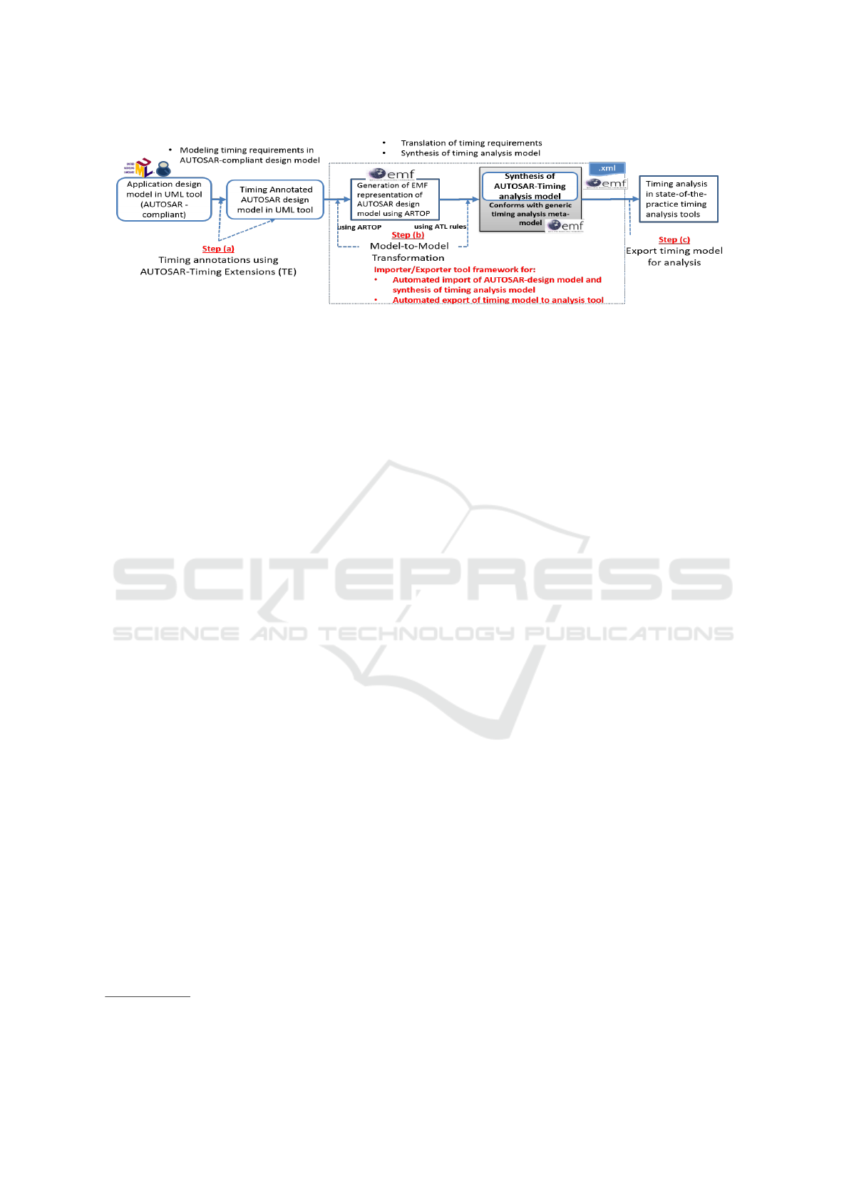
Figure 1: Systematic series of steps for early timing analysis in AUTOSAR-based ESE (introduced in (Iyenghar et al., 2020)).
system design. This is because fixing the errors be-
comes more costly during later development stages.
The AUTOSAR-Timing Extensions (TE) is a stan-
dardized formal timing model to capture timing con-
straints of automotive systems (AUTOSAR, 2017).
With this, it is possible to include the system’s timing
behavior already in the design models. For instance,
the timing requirements corresponding to end-to-end
response time could be modeling using AUTOSAR-
TE in the respective AUTOSAR-based design models
in UML tools. Analysis of these models can be car-
ried out in specialized timing analysis tools such as
Timing Architect
1
, chronSIM
2
and SymTA/S (Henia
et al., 2005) to obtain the end-to-end timing behavior
of the causal event chain.
In this context, a systematic series of steps for
early timing analysis in AUTOSAR-based ESE, in-
troduced in (Iyenghar et al., 2020), is shown in Fig.
1. Given an initial AUTOSAR-based system design
model (already modeled in a UML tool), the series of
steps illustrated in Fig. 1 is applied at an early stage in
the development process. Step-(a) in Fig. 1 involves
the specification of timing requirements in the design
model using AUTOSAR-TE to obtain a timing anno-
tated AUTOSAR-design model. With this model as
input to step (b), a timing analysis model is synthe-
sized in step (b) in Fig. 1. This timing analysis model
can then be provided as input to a timing analysis tool
as shown in step(c) in Fig. 1.
1.1 Relation to Authors’ Previous Work
A timing metamodel for synthesis of a timing anal-
ysis model from timing annotated design models is
proposed in (Iyenghar et al., 2016). It deals with time
modeling in generic ESE using UML. In (Iyenghar
and Pulvermueller, 2018), the timing metamodel in
(Iyenghar et al., 2016) is extended with energy prop-
erties and a methodology for energy-aware timing
1
https://www.timing-architects.com/
2
https://www.inchron.com/tool-suite/chronsim/
analysis for IoT use cases is proposed. But, (Iyeng-
har et al., 2016) and (Iyenghar et al., 2016) do not
deal with AUTOSAR-based ESE. More recently, a
systematic series of steps as indicated in Fig.1 for the
early synthesis of timing models in AUTOSAR-based
embedded software system is introduced in (Iyenghar
et al., 2020). The main scope of the work in (Iyeng-
har et al., 2020) concentrated on aspects such as mod-
eling timing requirements in AUTOSAR-based de-
sign model using AUTOSAR-TE (step (a) in Fig.
1) and its mapping to a generic timing metamodel
(Iyenghar et al., 2016). An initial generic example
of AUTOSAR-TE-model to timing-model transfor-
mations was also described.
1.2 Novel Contributions
The work presented in this paper builds up on the
work in (Iyenghar et al., 2020) and provides the fol-
lowing novel contributions (N1, N2 and N3):
N1 A light weight interfacing importer/exporter tool
framework, with plug-ins in Eclipse Modeling
Framework (EMF)(EMF, 2020), for automated
tooling of step (b) in Fig. 1 (highlighted with a
dotted rectangular box).
N2 An elaboration of different types of transforma-
tion rules and helpers implemented for an AU-
TOSAR importer, along with examples (step b in
Fig. 1).
N3 A full-fledged automotive use case with a specific
elaboration of an AUTOSAR-based causal event
chain and a detailed experimental evaluation (in-
cluding step (c) in Fig. 1)) are discussed.
In the remainder of this paper, background and related
work is presented in section 2. An elaborate automo-
tive use case of an Autonomous Emergency Braking
System (AEBS) case study (novelty N3) is presented
in section 3. An importer/exporter tool framework
(novelty N1), detailed model transformations (nov-
elty N2) and results of timing analysis are presented in
ENASE 2020 - 15th International Conference on Evaluation of Novel Approaches to Software Engineering
478
sections 4, 5 and 6 respectively. Section 7 concludes
the paper.
2 BACKGROUND AND RELATED
WORK
Model Driven Development (MDD)
3
, methodology
employing UML has been increasingly used for de-
sign and development in ESE, especially for modeling
automotive embedded software systems. Further, this
has also been applied for Non-Functional Properties
(NFR) such as timing, energy and reliability analysis
(Iyenghar et al., 2016), (Noyer et al., 2016a). In non-
UML contexts Matlab/Simulink (e.g. modeling con-
trol loops) (Franco and et. al, 2016), Rubus Compo-
nent Model (RCM) (Bucaioni et al., 2017), (Mubeen
et al., 2019) and EAST-ADL (Hans et al., 2009) are
among other established solutions used for ESE and
vehicular domain.
Apart from the aforementioned solutions, a com-
prehensive and well- established solution used in the
automotive sector is the AUTOSAR standard (AU-
TOSAR, 2018).
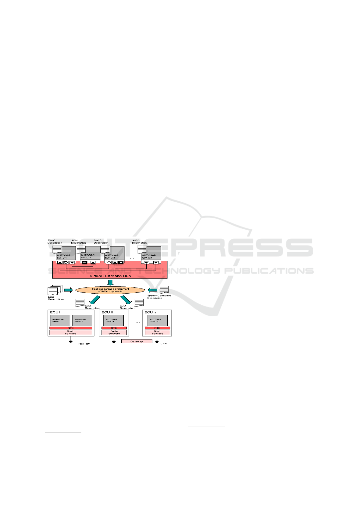
Figure 2: Various components of AUTOSAR framework &
mapping of Software Components (SW-Cs) to ECUs.
The various components of the AUTOSAR frame-
work are illustrated together with the mapping of soft-
ware components to ECUs, in the system configura-
tion step, in Fig. 2. AUTOSAR uses a component-
based software architecture, with central modeling el-
ements called Software Components (SWCs or SW-
Cs). The SWCs ( e.g., SW-C1 seen at the top of Fig. 2)
are used to structure the AUTOSAR model and group
functionality into individual components. These com-
3
https://www.omg.org/mda/
ponents can be connected together, oblivious of the
hardware they are running on. This is handled by the
Virtual Function Bus (VFB), which provides an ab-
straction layer for the SWC to SWC communication.
Components distributed over different ECUs how-
ever, may use the network bus for communication
(e.g., ECUs 1, 2..n communicating over FlexRay and
CAN buses in lower part of the Fig. 2). This is de-
termined automatically by the Run-Time Environment
(RTE), which is a communication interface for the
software components. In each ECU, the RTE provides
interfaces between SW-Cs (e.g. AUTOSAR SWC 1
and AUTOSAR SWC 2 in ECU 1 in lower part of Fig.
2) and between SW-C and Basic Software (BSW). In
this paper, the design model is created using the AU-
TOSAR framework and the timing properties are an-
notated using AUTOSAR-TE.
2.1 Timing Modeling and Analysis
Modeling and Analysis of RealTime and Embedded
Systems (MARTE)
4
is a standardized UML profile,
which extends UML and provides support for model-
ing the platform, software and hardware aspects of an
application (Anssi et al., 2011). Non-UML time mod-
eling alternatives include SystemC (Bhasker, 2010)
and Event-B
5
to name a few.
2.1.1 AUTOSAR-Timing Extensions
The AUTOSAR-Timing Extensions (TE) metamodel
feature an event-based model for the description of
the software’s temporal behavior and can be defined
on top of a system architecture. The AUTOSAR re-
lease with timing extensions and its own timing model
find extensive usage in the automotive industry (Hans
et al., 2009), (Peraldi-Frati et al., 2012) and (Ficek
et al., 2012). The TE metamodel provides five dif-
ferent views for timing specification, depending on
the kind of timing behavior described in the AU-
TOSAR model (AUTOSAR, 2017). The five views
are VfbTiming, SwcTiming (describes internal behav-
ior timing of SWC), SystemTiming, BswModuleTim-
ing and EcuTiming. In the experimental evaluation,
the SwcTiming view is employed, because the system
configuration and timing specification steps use the
SWCs. Further explanation of AUTOSAR method-
ology and AUTOSAR-TE are not provided here be-
cause of space limitations (interested readers are re-
ferred to (AUTOSAR, 2018)).
4
http://www.omg.org/omgmarte/
5
http://www.event-b.org/index.html
Automated End-to-End Timing Analysis of AUTOSAR-based Causal Event Chains
479
2.1.2 Autosar-based Causal Event Chain
In component-based ESE, individual sub-systems are
modeled with chains of components that are trans-
lated to chains of tasks for scheduling analysis.
The timing requirements of such chains, which we
coarsely refer to as the end-to-end delay can be spec-
ified in the component model and also estimated/ana-
lyzed during a timing analysis.
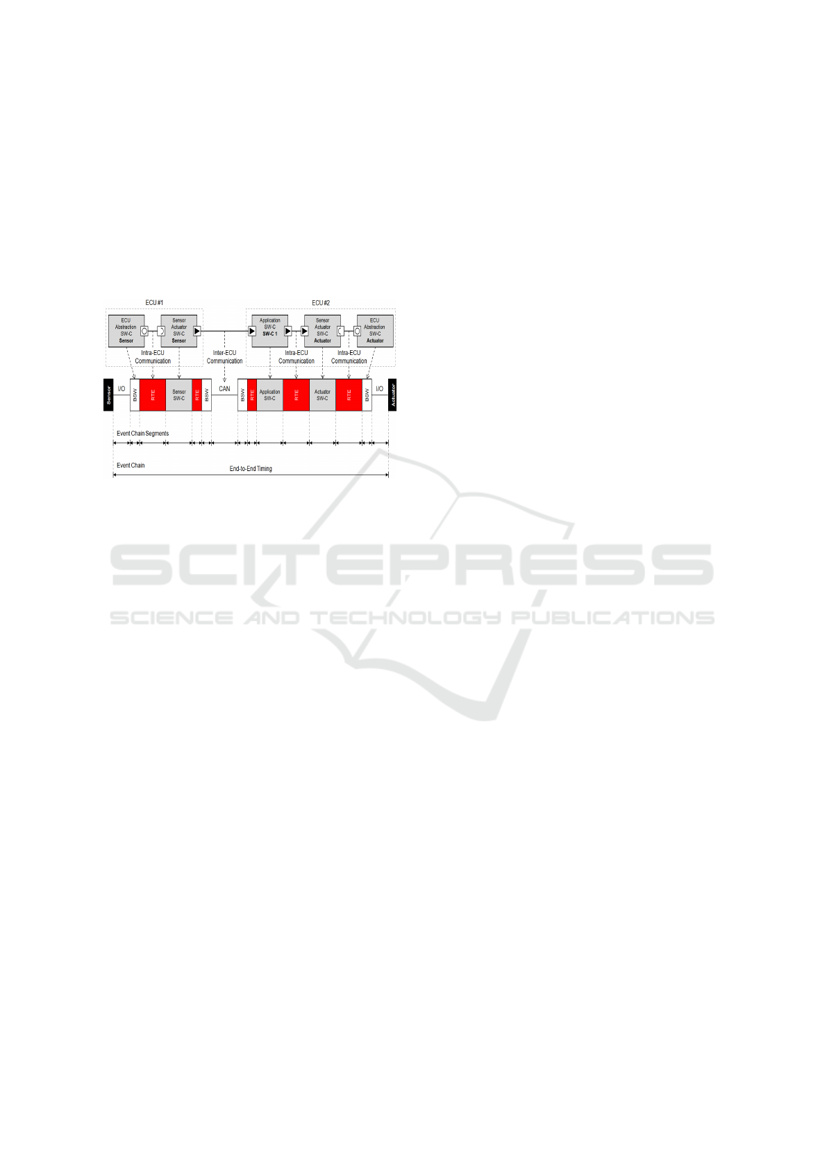
Figure 3: End-To-End timing of a AUTOSAR-based causal
event chain (AUTOSAR, 2017).
Fig. 3 shows an event chain end-to-end timing de-
scribing the causal dependency between ”Sensor” and
”Actuator”. The sequence of event chain segments
shows the details of end-to-end timing according to
the AUTOSAR timing views. A timing event chain
describes a causal order for a set of functionally de-
pendent timing events. Each event chain defines at
least the relationship between two differing events,
its stimulus and response which describe its start and
end point respectively. This means that if the stimulus
event occurs then the response event occurs after.
One way to guarantee that the system meets its
timing requirements is to perform pre-run-time anal-
ysis of it (e.g. already during design level), using
end-to-end timing analysis. Such analysis can vali-
date the timing requirements without performing ex-
haustive testing. In (Becker et al., 2017), methods to
compute end-to-end delays based on different levels
of system information is presented and evaluated in
an industrial case study. An evaluation of this work
is carried out in an automotive industrial case study,
using a commercial tool chain, Rubus-ICE. Similarly,
(Mubeen et al., 2019) targets the challenges that are
concerned with the unambiguous refinement of tim-
ing requirements, constraints and other timing infor-
mation among various abstraction levels. However,
the aforementioned works concentrates on usage of
EAST-ADL and Rubus Component Model and does
not concentrate on AUTOSAR, AUTOSAR-TE mod-
eling in UML tool or automated tooling for end-to-
end timing analysis.
2.1.3 Model-based Timing Analysis
The specified timing behavior can be analyzed us-
ing dedicated timing analysis tools such as Cheddar
(Singhoff et al., 2004) and MAST (Harbour et al.,
2001). Popular proprietary timing analysis tools in-
clude chronSIM , SymTA/S and Timing Architect.
These tools are independent of the modeling lan-
guages used. Therefore, they require the timing
specifications to be in a particular format, although
some provide import functions for common model-
ing languages. But, there is no tool support for auto-
mated synthesis and export of AUTOSAR-based tim-
ing analysis model (from AUTOSAR-based applica-
tion design model in UML tools) to these timing anal-
ysis tools. AUTOSAR-TE is used for a model-based
timing analysis in works such as (Klobedanz et al.,
2010), (Kim et al., 2016) and (Scheickl et al., 2012).
However, a systematic model-based approach in tim-
ing analysis of AUTOSAR-based systems in timing
analysis tools is missing.
2.2 Gaps Identified and Challenges
Addressed
On examining the related literature and state-of-the-
practice tools, it can be stated that several related
work deal with examination of the required timing
properties for end-to-end timing analysis. Many in-
dustrial tools implement the end-to-end delay analy-
sis for event chains. These exist as island solutions
without an automated integrated workflow from tim-
ing specification in design model to timing analysis.
They further require manual creation and/or export of
timing-analysis-model artifacts in the analysis tool,
for timing analysis. Thus, automated timing analysis
(e.g. end-to-end delay) of AUTOSAR-based systems
(e.g. causal event chains) described in UML tool (e.g.
Rhapsody developer) in state-of-the-practice timing
analysis tool (e.g. SymTA/S) is missing. This is a sig-
nificant step to address and evaluate automated tool-
ing for checking and monitoring software quality.
3 USE CASE: AUTONOMOUS
EMERGENCY BRAKING
SYSTEM (AEBS)
The main purpose of an Autonomous Emergency
Braking Systems (AEBSs) is to warn the driver in
case of an imminent frontal collision. This commonly
ENASE 2020 - 15th International Conference on Evaluation of Novel Approaches to Software Engineering
480
happens through visual and acoustic warning signals
as a first step. The next level of warning is often a
tactile warning. The AEBS in cars use the Time-To-
Collision (TTC) value (van der Horst and Hogema,
1993), (Kusano and Gabler, 2011) to estimate the dan-
ger of the situation. It is defined as the time left until a
collision happens, if every object (e.g. both cars) con-
tinues to move at the same speed. To calculate TTC,
AEBS needs data such as the distance to frontal ob-
jects (e.g. from radar sensors) and wheel speed sensor
input at certain speed ranges. In this paper, based on
the systems used in current automobiles, a simplified
version of an AEBS is modeled as an use case and
used for experimental evaluation.
3.1 Requirements Specification
To have an exact description of the functionality pro-
vided by AEBS, several Functional (FR) and Non-
Functional Requirements (NFR) were implemented
for this use case.
3.1.1 Functional Requirements
FR 1: The assistant shall support the driver in
avoiding frontal collision.
FR 2: The system needs constant information
about the car’s speed.
FR 3: The distance to the next car in the same
lane shall be measured constantly.
FR 4: The assistant shall prepare the brake sys-
tem when TTC falls below 6s.
FR 4: The assistant shall warn the driver when
the TTC falls below 5 seconds: Before intervening
with an autonomous braking, the assistant needs
to warn the driver in multiple stages of the immi-
nent danger, so that the driver can react appropri-
ately. These stages are entered consecutively with
decreasing TTC.
• Visual: Warning light (TTC=5s): A warning
lamp shall provide a first visual warning.
• Accoustic: Warning sound (TTC=4s): An au-
dible signal shall provide a second warning.
• Tactile: Warning jolt (TTC=3s): A warning jolt
shall precede initiation of a full brake.
FR 5: The assistant shall engage an emergency
braking when the TTC falls below 1.5 seconds:
3.1.2 Non-Functional Timing Requirements
NFR 1: The system estimates TTC every 50 ms
NFR 2: The relative speed of the next car must be
calculated every 50 ms
NFR 3: The speed of the car must be sampled ev-
ery 10 ms
NFR 4: The distance to the next car must be sam-
pled every 10 ms
NFR 5: The load on the ECU processing cores
must not exceed 80%
NFR 6: New sensor data must influence the TTC
computation after a maximum delay of 200ms:
The system needs to react fast to sudden speed
changes, so the end-to-end response time from
sensor measurements to a reaction needs to be be-
low 200 ms.
3.2 Control Flow
The AEBS use case is connected to sensors such as
speed and radar sensors and actuators such as the
warning LED, speaker and brakes via a software in-
terface. Thus information such as the speed of the
car in ms
−1
(from wheel speed sensor), distance in
m and relative speed in ms
−1
(from radar sensor) are
provided as inputs to the AEBS system. The system
is connected to the output actuators such as, Warning
LED (with on/off state), speaker (with the ability to
create an acoustic warning signal) and brakes (need to
have a preparation, warning brake and an emergency
brake functionality) for respective output action.
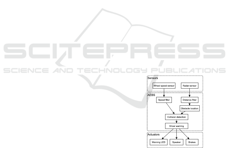
Figure 4: Control flow and modules of the AEBS.
Based on the control logic of the Collision Mitigation
Brake System used in (Sugimoto and Sauer, 2005),
the AEBS basic control flow is shown in 4. It shows
the above-mentioned sensors and actuators as sys-
tem input and output, as well as the AEBS modules.
The sensor values are both processed by filter mod-
ules (Speed filter and Distance filter), which retrieve
them periodically, filter outliers and smooth the sen-
sor noise. The distance information from the radar
Automated End-to-End Timing Analysis of AUTOSAR-based Causal Event Chains
481

sensor is then further processed by the Obstacle lo-
cation module. It stores the filtered distance values
of consecutive measurements and calculates the rel-
ative speed of a proceeding car from the change of
distance over time. These values are used in the Col-
lision detection module, to estimate the TTC. If the
filtered speed sensor value is above a certain thresh-
old, indicating a normal driving state, the TTC is sent
to the Driver warning module. This triggers different
stages of warnings, depending on the criticality of the
TTC value, or sets off an emergency braking as last
resort respectively. If the warning measures are suc-
cessful and the TTC rises above the thresholds again,
the corresponding warnings are cancelled.
3.3 AUTOSAR-based Design Model
Given the requirements and the control flow of the
AEBS, the AUTOSAR system description of the
AEBS is modeled using the IBM Rational Rhapsody
Developer modeling tool (IBM Software, 2019). This
tool is among the popular UML modeling tool with
AUTOSAR support used in the automotive industry,
hence it is used in this paper. The first step in im-
plementing the AUTOSAR design model is to define
the software components, of which the system is com-
posed of. This is shown in Fig. 5 and described below.
The sensor filter modules on the left-hand side
of Fig. 5 are modeled as SensorActuatorSwCom-
ponentTypes. They have client ports (speedSensor-
Port, radarSensorPort) to connect to the correspond-
ing sensors. These ports are typed by ClientServer-
Interfaces that provide an operation for retrieving the
sensor value. This is illustrated by the association be-
tween the ports and the interfaces, which is stereo-
typed as a portType. The rest of the modules are
modeled as ApplicationSwComponentTypes, as they
do not directly represent a sensor or an actuator.
The communication between the sensor filters and
the CollisionDetection and ObstacleLocation compo-
nents happens through sender/receiver ports. The fil-
tered dataElements get sent to the processing com-
ponents. Equally, the ObstacleLocation sends a
list of obstacles (comprising of distance and relative
speed) to the CollisionDetection. The communica-
tion between CollisionDetection and DriverWarning
is also typed as sender/receiver and the corresponding
dataElement is the TTC value.
In the end, the DriverWarning component is con-
nected by client ports (ledPort, speakerPort and
brakePort) to the three actuators. The correspond-
ing interfaces provide the necessary operations for
the different levels of driver warning, e.g., setting
the warning LED light status (setLight), playing a
warning sound (playWarningSound) or performing an
emergency brake (emergencyBrake).
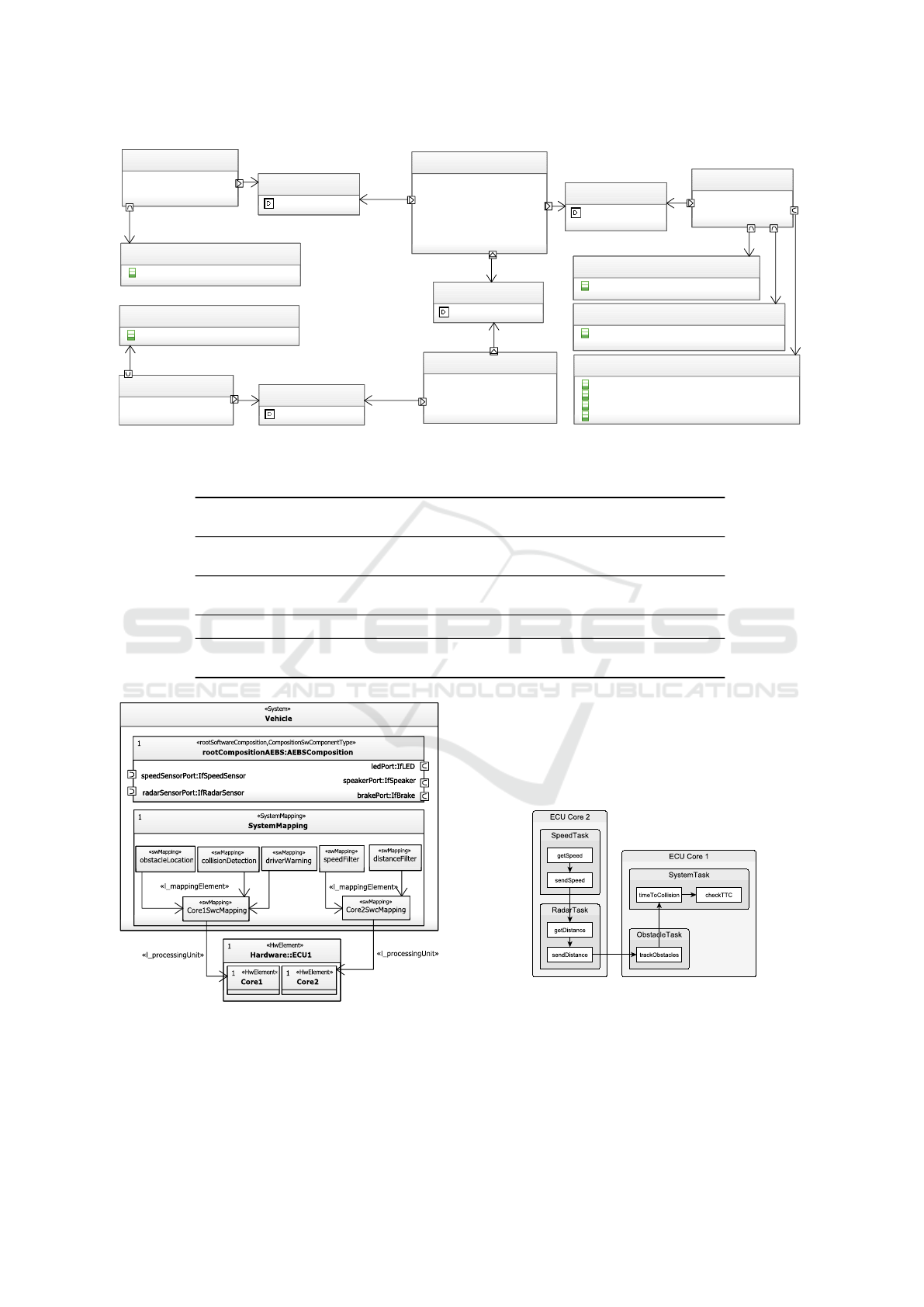
3.3.1 Overall System Description
The system diagram of the AEBS design model is
shown in Fig.6. It contains a SystemMapping element,
which maps the software components to ECUs or to
ECU cores respectively. The mapping is necessary for
conducting a timing analysis, because it also maps the
runnables of the software component’s internal be-
havior to an ECU or an ECU core respectively. It also
indicates, which function will be executed on which
processing unit later on. In the system mapping, for
every processing core, a swMapping element linking
to the corresponding hwElement from the ECU dia-
gram with l processingUnit is created. Then, for ev-
ery software component prototype, a swMapping that
links to the core mappings with l mappingElement
is created. These prototype mapping elements ref-
erence the component prototypes with their tagged
value component.
3.4 Timing Behavior
To perform a timing analysis of the AEBS and verify
the results against the timing requirements from 3.1.2,
the timing behavior of the AEBS has to be captured.
For this, a more detailed division of the modules in
functions and a specification of the Core Execution
Time (CET)
6
is needed. The functions need to be al-
located to tasks, which in turn are allocated to pro-
cessing cores.
This detailed architecture of the AEBS can be seen
in 7. The system is distributed over two processing
cores on one ECU. The ECU Core 2 is responsible
for handling the sensor tasks, which consist of a func-
tion for retrieving the data (getSpeed, getDistance)
and filtering/sending the data (sendSpeed, sendDis-
tance). The ECU Core 1 handles the ObstacleTask
and SystemTask, which handle the tracking of obsta-
cles and calculating/checking the TTC value.
Table 1 lists the detailed timing properties of the
functions and tasks. It shows the guaranteed mini-
mum and maximum CET of the functions, which can
be obtained using experience values from experts (as
in this paper) or run-time measurements of already
implemented functions. The periodic activation of the
functions is taken from the timing requirements and
grouped into fixed priority tasks. The priority val-
ues are assigned depending on the importance of the
6
Length of time the task could take to execute on a spe-
cific hardware platform.
ENASE 2020 - 15th International Conference on Evaluation of Novel Approaches to Software Engineering
482
CollisionDetection
«ApplicationSwComponentType»
obsPort:IfObstacles
speedPort:IfSpeed
TTCPort:IfTTC
obsPort:IfObstacles
speedPort:IfSpeed
TTCPort:IfTTC
ObstacleLocation
«ApplicationSwComponentType»
distPort:IfDistance
obsPort:IfObstacles
distPort:IfDistance
obsPort:IfObstacles
DriverWarning
«ApplicationSwComponentType»
brakePort:IfBrake
speakerPort:IfSpeaker
ledPort:IfLED
TTCPort:IfTTC
brakePort:IfBrake
speakerPort:IfSpeaker
ledPort:IfLED
TTCPort:IfTTC
SpeedFilter
«SensorActuatorSwComponentType»
speedSensorPort:IfSpeedSensor
speedPort:IfSpeed
speedSensorPort:IfSpeedSensor
speedPort:IfSpeed
DistanceFilter
«SensorActuatorSwComponentType»
radarSensorPort:IfRadarSensor
distPort:IfDistance
radarSensorPort:IfRadarSensor
distPort:IfDistance
IfTTC
«SenderReceiverInterface»
«dataElement» ttc:int
IfLED
«ClientServerInterface»
«ClientServerOperation» setLight(on:Boolean):void
IfSpeaker
«ClientServerInterface»
«ClientServerOperation» playWarningSound():void
IfBrake
«ClientServerInterface»
«ClientServerOperation» emergencyBrake():void
«ClientServerOperation» prepareBrake():void
«ClientServerOperation» releaseBrake():void
«ClientServerOperation» warningBrake():void
IfSpeedSensor
«ClientServerInterface»
«ClientServerOperation» getSensorValue():int
IfRadarSensor
«ClientServerInterface»
«ClientServerOperation» getSensorValue():int
IfSpeed
«SenderReceiverInterface»
«dataElement» speed:int
IfDistance
«SenderReceiverInterface»
«dataElement» distance:int
IfObstacles
«SenderReceiverInterface»
«dataElement» obstacles:list
Figure 5: AEBS software components as seen in the software component diagram modeled in Rhapsody.
Table 1: Timing behavior of system functions.
Module Function
CET (ms) Period
Task
Task
min – max (ms) priority
Speed filter
getSpeed 1 – 2 10
SpeedTask 0
sendSpeed 4 – 6 50
Distance filter
getDistance 1 – 2 10
RadarTask 1
sendDistance 4 – 6 50
Obstacle location trackObstacles 6 – 10 50 ObstacleTask 2
Collision detection timeToCollision 5 – 7 50
SystemTask 5
Driver warning checkTTC 3 – 5 50
Figure 6: System diagram containing the system mapping
and the root software composition.
task, where higher values correspond to more impor-
tant tasks.
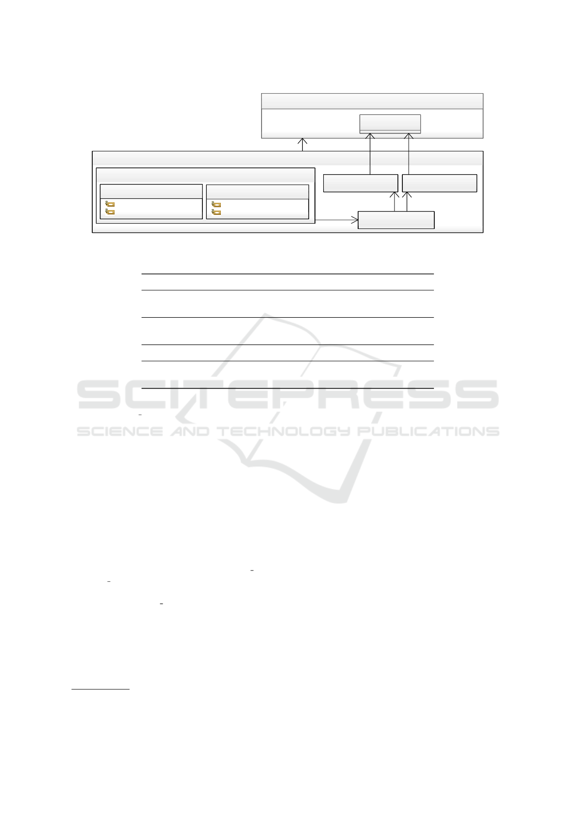
3.5 Timing Modeling
The timing constraints of the AEBS are added to the
model in Fig. 5 with the help of AUTOSAR-TE in the
UML tool Rhapsody.
Figure 7: AEBS architecture and end-to-end execution path.
Fig. 8 shows a latency constraint for the checkTTC
runnable entity of the DriverWarning software com-
ponent (seen at top-right of Fig. 5). An SwcTim-
ing is created for each software component in the
AEBS, which link to the component’s internal be-
Automated End-to-End Timing Analysis of AUTOSAR-based Causal Event Chains
483
DriverWarningTiming
«SwcTiming»
checkTTCActivated
«TDEventSwcInternalBehavior»
checkTTCTerminated
«TDEventSwcInternalBehavior»
checkTTCLatencyConstraint
«LatencyTimingConstraint,role_timingGuarantee»
minLatency
«minimum»
cseCode:CseCodeType=3
cseCodeFactor:RhpInteger=3
maxLatency
«maximum»
cseCode:CseCodeType=3
cseCodeFactor:RhpInteger=5
checkTTCEventChain
«TimingDescriptionEventChain»
«l_response»
«l_stimulus»
«l_scope»
Application::SoftwareComponents::DriverWarning::IBDriverWarning
1
«SwcInternalBehavior»
checkTTC
1
«RunnableEntity»
«l_runnable» «l_runnable»
«l_behavior»
Figure 8: Timing attributes for the checkTTC runnable entity.
Table 2: Task properties and mapped runnable entities (configuration for timing analysis).
Task Priority Period Preemptible Runnable entities
SpeedTask 0 10 ms Yes
getSpeed
sendSpeed
RadarTask 1 10ms Yes
getDistance
sendDistance
ObstacleTask 2 50ms Yes trackObstacles
SystemTask 5 50ms Yes
timeToCollision
checkTTC
havior with the l behavior association. Inside these
elements, two TDEventSwcInternalBehaviors are de-
fined for each runnable entity (in this case, checkTTC
of IBDriverWarning). The first event highlights the
activation of the runnable, while the second highlights
the termination. This is defined by setting the tag td-
EventSwcInternalBehaviorType of the timing event to
either runnableEntityActivated or runnableEntityTer-
minated. Both these events are now used to form
a TimingDescriptionEventChain, in which the event
chain stimulus is the runnable activation and the event
chain response is the runnable termination.
Finally, the core execution time of the runnable
checkTTC is specified by the checkTTCLatency-
Constraint that links to its event chain with l scope.
The role timingGuarantee stereotype declares that
this constraint is the expected execution time instead
of a requirement (role timingRequirement). The re-
lated timing information can be given as maximum
and minimum execution time and is specified by
ASAM-CSE
7
codes. The cseCode specifies the time
base (e.g., 2 = 100µs, 3 = 1ms and 4 = 10ms) and the
cseCodeFactor determines an integer scaling factor.
Thus, in this case, the execution time of the check-
TTC runnable entity lies between 3ms and 5ms. Note
7
https://www.asam.net/
that every runnable entity in the model is similarly
specified with their respective timing requirements.
3.5.1 Causal Event Chain Example
Given the timing annotated AUTOSAR-design
model, the time critical path of AEBS system is
identified. Let us consider which states that, new
sensor data must influence the TTC computation
after a maximum delay of 200ms. Thereby, the
system needs to react fast to sudden speed changes,
so the end-to-end response time (delay) from sensor
measurements to a reaction needs to be below 200
ms. The end-to-end flow of the AEBS system (cf.
Fig. 4), from sensor input to possible actuator output,
in which the needs to be satisfied, is an example of a
causal event chain (cf.section 2.1.2). This is referred
hereafter as systemEventChain:. It is depicted by
the function path in Fig. 7, namely getSpeed →
sendSpeed → getDistance → sendDistance →
trackObstacles → timeToCollision → checkTTC.
This describes the time critical path between the
event requesting the speed of the vehicle (stimulus)
and the event making available the determined TTC
value (response).
During timing modeling, this event chain is mod-
ENASE 2020 - 15th International Conference on Evaluation of Novel Approaches to Software Engineering
484

eled as an end-to-end execution path through the sys-
tem. As this path spans over runnables from different
software components, it does not belong to a specific
SwcTiming. Thus, a VfbTiming element is created to
contain the execution path event chain. It comprises
of a sequence of runnable event chains (e.g. the check-
TTCEventChain in Fig. 8) to highlight the execution
path of runnable entities.
3.5.2 Task Configuration for Timing Analysis
There are four tasks specified in the AEBS model (Ta-
ble 2), as part of ECU configuration. They are, two
sensor tasks namely, SpeedTask and RadarTask, Ob-
stacleTask for the ObstacleLocation component and
SystemTask for the CollisionDetection and Driver-
Warning components. Every task is provided with a
fixed OsTaskPriority, where higher values indicate a
more important task and period. Then the runnable
entities are mapped to the corresponding task (e.g.
runnables getSpeed and sendSpeed are mapped to the
task SpeedTask as shown in Table 2). The respective
task properties and the mapping of runnables to tasks
in their specified order are shown in Table 2. At this
point, there is enough information contained in the
model to analyze the timing behavior of the AEBS.
The model is now exported from the underlying UML
representation(in UML tool (IBM Software, 2019)) to
an interchangeable ARXML file (AUTOSAR, 2018).
4 IMPORTER/EXPORTER
FRAMEWORK
An AUTOSAR importer (cf. Fig. 9-(b)), is im-
plemented, as part of a lightweight interfacing tool
framework shown in Fig. 9-(a). A prototype of the
importer/exporter tool (Fig. 9-(a)) is implemented
in Java using the Plug-in Development Environment
(PDE) of the Eclipse IDE. The tool provides inter-
faces for creating new model importers, which can
be integrated with the tool using the Eclipse exten-
sion point mechanism. This avoids tight coupling be-
tween the tool itself and the modeling domain inter-
faces (Noyer et al., 2016b).
In this manner, a new plug-in for the AUTOSAR
modeling domain is created, as seen in Fig. 9-(b).
The main plug-in classes are contained in the autosar
package. The class AutosarImporter extends the Ab-
stractImporter class from the importer/exporter tool,
to implement the necessary methods for importing
models. It also provides the necessary user interface
messages (from Messages class) and an option for se-
lecting the source ARXML file. This file is the timing
annotated AUTOSAR-based design model exported
from UML modeling tool (cf. section 3.3–3.5).
The connection to the importer/exporter tool is
then established by defining an extension point in the
plug-in. The AutosarImporter class is hereby speci-
fied as the importer class, which will be called when
the import process is invoked by the importer/exporter
tool. Thereupon, the AutosarToTimingCAT class from
the converter.autosar package is called from the im-
porter class to handle the model transformation of the
specified AUTOSAR source model. It contains the
Model-to-Model (M2M) transformations (cf. section
5) and references to the used AUTOSAR and tim-
ing metamodels. The AutosarResourceSetImpl class
from the Artop framework is thereby used for han-
dling ARXML files.
5 MODEL TRANSFORMATIONS
The AUTOSAR importer imports the timing anno-
tated AUTOSAR-based design model in ARXML for-
mat. With this as input, M2M transformations im-
plemented in Atlas Transformation Language (ATL)
8
,
are invoked for synthesis of a timing analysis model
(step (b) in Fig. 1). The ATL implementation in
the prototype follows the regular structure of ATL
transformations. The source, transformation and tar-
get models each have their own separate metamodels,
which are each based on a common meta-metamodel,
namely ECORE (EMF, 2020). Here the source model
(i.e., the timing annotated AUTOSAR-based design
model) in ARXML format, conforms with the AU-
TOSAR metamodel (AUTOSAR, 2018). The target
metamodel is a timing metamodel. In this work, a
generic timing metamodel developed using the EMF
(EMF, 2020) and introduced in (Iyenghar et al., 2016)
is employed. This metamodel comprises of a basic
set of timing properties needed for performing a tim-
ing analysis. This can be termed as a generic meta-
model, as it closely adheres with timing models used
in several timing validation tools (e.g. SymTA/S).
The M2M transformations are implemented as an
ATL module, Autosar2Timing in the file autosarTo-
Timing.atl. In this module, there are 13 matched
rules for all conditional mappings and 2 lazy rules
for all unconditional mappings. The matched rules
are used for source elements such as model, package
and classes. Lazy rules are used for source elements
that satisfy specific conditions and must be called ex-
plicitly for creating target elements. In addition, 16
helpers are implemented which may be invoked by
8
http://www.eclipse.org/atl/
Automated End-to-End Timing Analysis of AUTOSAR-based Causal Event Chains
485
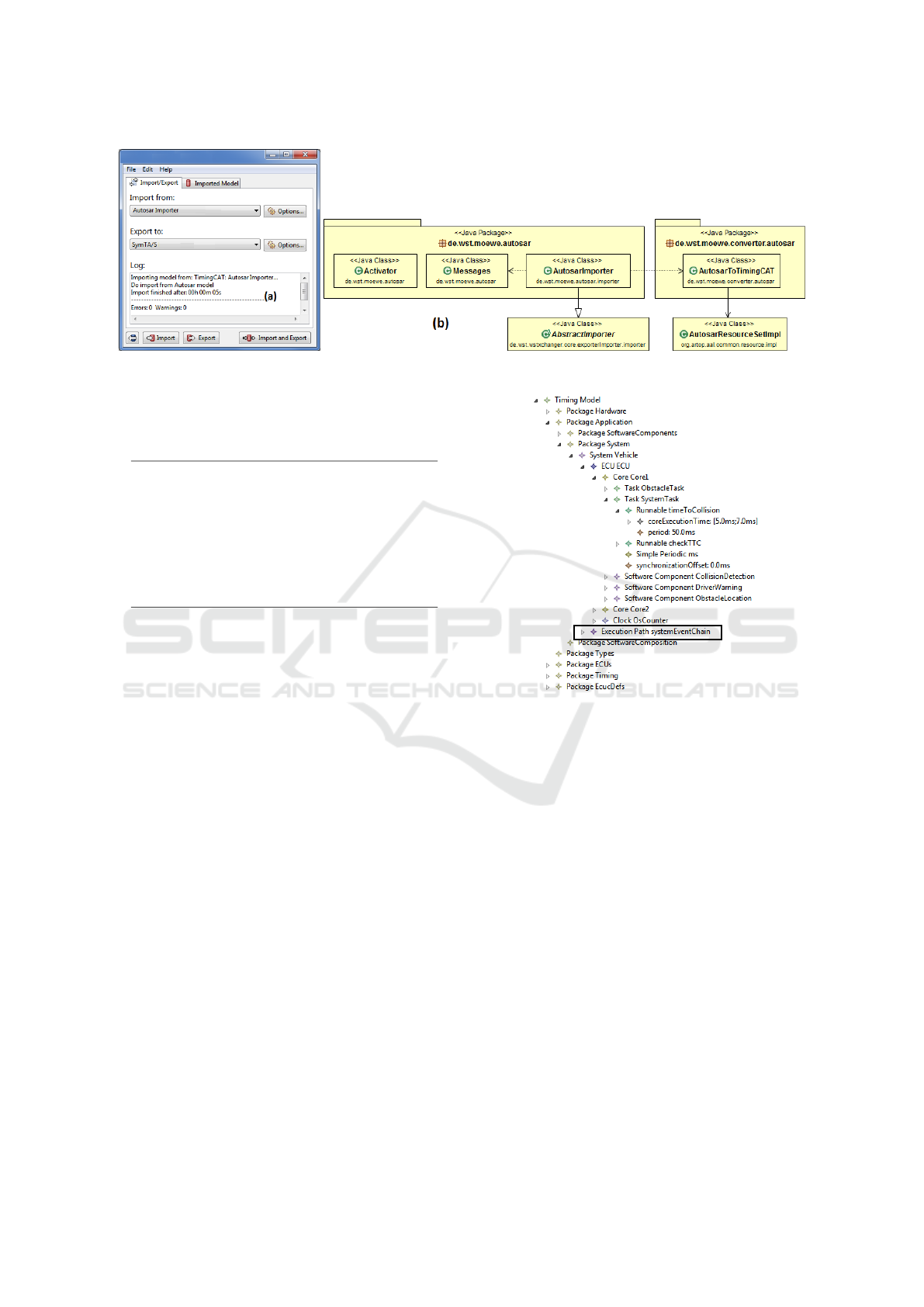
Figure 9: (a) Lightweight importer/exporter interfacing tool framework and (b) AUTOSAR importer class diagram.
the transformation rules. The helpers are used as get-
ter() and setter() methods.
Listing 1: An example of ATL rules.
1 rule A tomic S WC 2 SW C om p on e nt extends
2 I d e n t i f i a b l e 2 I C A T O b j e c t {
3 from
4 inp ut : AR ! A t o m i c S w C o m p o n e n t T y p e
5 to
6 ou t pu t : Ti mi n g ! S o f tw a r e C o m po n en t (
7 ru nn ab le s <- in put . i n t e rn a lB e h a v i o rs
8 -> c ol le ct ( ib | ib . r un na bl es )
9 -> fl a t t en ()) }
A simple example of an ATL matched rule is shown
in Listing 1. The AtomicSWC2SWComponent rule
extends the parent rule Identifiable2ICATObject
and thus, its target pattern is inherited. This means
that, the target element SoftwareComponent au-
tomatically receives the name and description at-
tributes from parent rule (i.e., Identifiable2ICAT-
Object-not listed here) . Additionally, it receives the
runnables attribute specified in the new target pat-
tern, to link to the software component’s runnables.
The collect operation iterates through all inter-
nal behavior elements (ib) and returns the list of
runnables for each. As this statement returns a two-
dimensional list, the flatten operation ensures that
a list directly containing the runnables is returned
and assigned to the runnables attribute. The rest
of the rules are created similarly, such that all the
AUTOSAR-TE elements are mapped to the timing
metamodel elements. In the end, the ATL execution
engine is able to produce a corresponding output tim-
ing model from an AUTOSAR input model by use
of the ATL file. This model transformation is inte-
grated into the AUTOSAR importer in the extensible
importer/exporter tool chain (cf. section 4).
The synthesized AUTOSAR-timing analysis
model of the AEBS use case is shown in Fig. 10.
The necessary elements for a timing analysis were
Figure 10: Synthesized timing model of AEBS use case.
extracted from the AUTOSAR design model anno-
tated with timing properties (cf. Fig. 5, 8). As seen
in Fig. 10, the AEBS model is structured by different
Packages and the System element contains the com-
plete software and hardware elements in a hierarchy.
For example, the runnable timeToCollision with its
corresponding execution time can be seen, allocated
to the SystemTask, which is in turn allocated to Core1
of the ECU. The execution path systemEventChain in
Fig. 10 is the causal event chain systemEventChain
described in section 3.5.1.
The resulting timing analysis model is exported
to the timing analysis tool SymTA/S for end-to-end
timing analysis. This is carried out using the Sym-
TA/S exporter (cf. Fig. 9-(a)), which communicates
with the SymTA/S tool using its remote interface.
If the export process was successful, a new project
is created with the corresponding elements from the
timing model in the SymTA/S representation. The
same elements from the timing model, annotated with
timing properties, are now available inside SymTA/S
tool.
ENASE 2020 - 15th International Conference on Evaluation of Novel Approaches to Software Engineering
486
8 ms
12 ms
2 ms
(c)
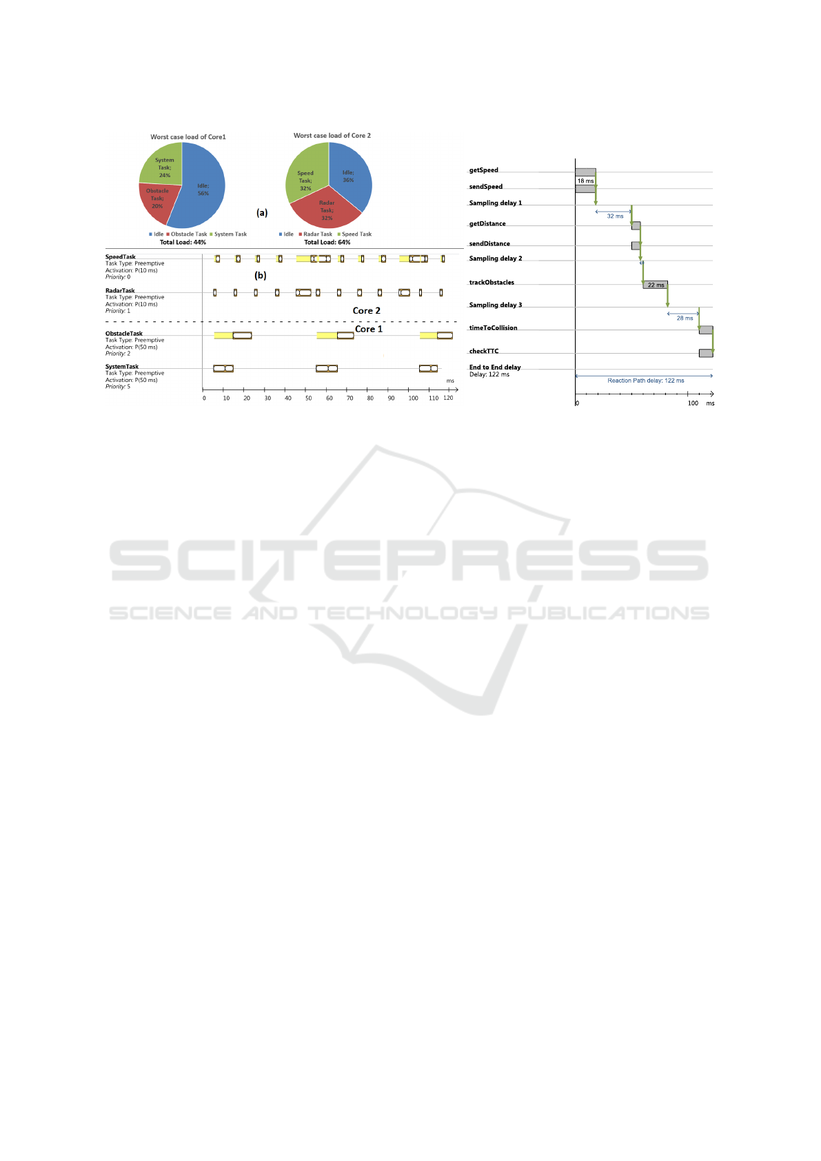
Figure 11: (a) Worst case load of processing cores 1 & 2 (b) Exemplary task scheduling for system distribution analysis and
(c) Worst case response time for the causal event chain systemEventChain modeled in use case (ref. section 3.5.1).
6 RESULTS OF THE TIMING
ANALYSIS
Once the timing model (from section 5) is exported to
SymTA/S, timing analysis can be carried out and re-
sults can be visualized graphically in the tool. For the
AEBS use case, the results from processor utilization
analysis, worst-case scheduling analysis and end-to-
end latency analysis are described below.
Fig. 11-(a) shows the worst case processor work-
load as pie charts for processing cores 1 and 2. It is
seen that, even in the worst case, the system is schedu-
lable and both cores still have resources left (56% idle
time for core1 and 36% idle time for core 2). Thus,
the timing requirement in section 3.1.2 is satisfied for
this set of function execution times.
The detailed scheduling of the AEBS tasks for the
cores is seen in a Gantt chart by Fig. 11-(b). It pro-
vides an exemplary iteration of the system distribu-
tion analysis. The upper half shows the scheduling
of Core2 and the lower one shows the scheduling of
Core1, which are independent of each other. Each
task has different activation periods and priorities and
executes a set of runnables, which are depicted as
blocks on the timeline. If a task is preempted, e.g.,
because of a higher priority task, this is expressed by
a yellow backdrop in the timeline.
As seen in Fig. 11-(b), the SpeedTask tries to ex-
ecute the getSpeed runnable every 10ms. But as the
RadarTask also executes its getDistance function ev-
ery 10ms and has a higher priority this is delayed until
the end of the RadarTask execution. The same applies
for the sendSpeed operation, which is to be executed
every 50ms, but has to wait for the sendDistance op-
eration. Thus, this provides an extensive overview of
the possible scheduling behavior of the software sys-
tem. It also confirms that the ECU will be able to
schedule the system and obstacle tasks every 50ms,
and the sensor tasks every 10ms. Hence, the timing
requirements to from section 3.1.2 are satisfied.
The worst case response times for end-to-end ex-
ecution paths as evaluated during timing analysis is
shown in Fig. 11-(c). It shows the systemEventChain
as specified in the AUTOSAR model in a Gantt chart.
The runnables of the AEBS contained in the event
chain are executed consecutively. This leads to a
worst case response time of 122ms, which satisfies
the system end-to-end path timing requirement from
section 3.1.2.
7 CONCLUSIONS
In this paper, we have presented a detailed evaluation
of a novel approach in ESE towards automated tim-
ing analysis of AUTOSAR-based systems. A specific
example of a widely used timing analysis measure for
automotive systems namely, end-to-end delay analy-
sis is described with the help of an AUTOSAR-based
causal event chain example.
The elaborate use case presented in this paper, was
in early design phase without implementation (e.g. no
function definitions). However, the timing analysis
provided an outlook on the estimated timing behavior
Automated End-to-End Timing Analysis of AUTOSAR-based Causal Event Chains
487

of the system. This additional knowledge at an early
stage could be very beneficial to the ECU develop-
ment process. For instance, the additional resources
(e.g. processor workload) could be utilized to further
extend or improve the functionality of AEBS (e.g. by
decreasing the period of the system end-to-end path)
or replace the ECU with a slower, cheaper version, to
save costs in mass production. At this development
stage, such design changes are still possible without
major consequences.
ACKNOWLEDGEMENTS
This work is supported by a grant (id:
KF2312004KM4) from BMWi-ZIM co-operation,
Germany and carried out in cooperation with Willert
Software Tools GmbH and SymtaVision GmbH.
The authors thank Stephan Wessels M.Sc (Uni
Osnabrueck) and Dr. Arne Noyer (Willert Software
Tools) and for their contribution with AEBS use case
and importer/exporter tool respectively.
REFERENCES
Anssi, S., G
´
erard, S., Kuntz, S., and Terrier, F. (2011). AU-
TOSAR vs. MARTE for enabling timing analysis of
automotive applications. In International SDL Forum,
pages 262–275. Springer.
AUTOSAR (2017). Specification of timing ex-
tensions. https://www.autosar.org/fileadmin/
user upload/standards/classic/4-3/AUTOSAR
TPS TimingExtensions.pdf. Accessed Jan 2020.
AUTOSAR (2018). Release 4.4.0: Methodology
and templates. https://www.autosar.org/standards/
classic-platform/classic-platform-440/. Accessed
Nov 2019.
Becker, M., Dasari, D., Mubeen, S., Behnam, M., and
Nolte, T. (2017). End-to-end timing analysis of cause-
effect chains in automotive embedded systems. Jour-
nal of Systems Architecture, 80:104 – 113.
Bhasker, J. (2010). A SystemC Primer. Star Galaxy.
Bucaioni, A., Cicchetti, A., Ciccozzi, F., Mubeen, S., and
Sj
¨
odin, M. (2017). A metamodel for the rubus com-
ponent model: Extensions for timing and model trans-
formation from east-adl. IEEE Access, 5:9005–9020.
EMF (2020). Eclipse modeling framework. https://www.
eclipse.org/modeling/emf/. Accessed Jan 2020.
Ficek, C., Feiertag, N., Richter, K., and Jersak, M. (2012).
Applying the AUTOSAR timing protection to build
safe and efficient ISO 26262 mixed-criticality sys-
tems. Proceedings of ERTS.
Franco, F. R. and et. al (2016). Workflow and toolchain for
developing the automotive software according autosar
standard at a virtual-ecu. In 2016 IEEE 25th Inter-
national Symposium on Industrial Electronics (ISIE),
pages 869–875.
Hans, B., Rolf, J., and Henrik, L. (2009). Annotation with
Timing Constraints in the Context of EAST-ADL2
and AUTOSAR-the Timing Augmented Description
Language. In STANDRTS’09.
Harbour, M. G., Garc
´
ıa, J. G., Guti
´
errez, J. P., and Moyano,
J. D. (2001). Mast: Modeling and analysis suite for
real time applications. In Real-Time Systems, 13th Eu-
romicro Conference on, 2001., pages 125–134. IEEE.
Henia, R., Hamann, A., Jersak, M., Racu, R., Richter, K.,
and Ernst, R. (2005). System level performance anal-
ysis – the symta/s approach. IEE Proceedings – Com-
puters and Digital Techniques, 152(2):148–166.
IBM Software (2019). Ibm rational rhapsody de-
veloper. https://www.ibm.com/software/products/en/
ratirhap. Accessed Nov 2019.
Iyenghar, P., Huning, L., and Pulvermueller, E. (2020).
Early synthesis of timing models in autosar-based au-
tomotive embedded software systems. In 8th Interna-
tional Conference on Model-Driven Engineering and
Software Development.
Iyenghar, P., Noyer, A., Engelhardt, J., Pulverm
¨
uller, E.,
and Westerkamp, C. (2016). End-to-end path delay
estimation in embedded software involving heteroge-
neous models. In 11th IEEE Symposium on Industrial
Embedded Systems, SIES, 2016, pages 183–188.
Iyenghar, P. and Pulvermueller, E. (2018). A model-driven
workflow for energy-aware scheduling analysis of iot-
enabled use cases. IEEE Internet of Things Journal,
5(6):4914–4925.
Kim, J. H., Kang, I., Kang, S., and Boudjadar, A.
(2016). A process algebraic approach to resource-
parameterized timing analysis of automotive software
architectures. IEEE Transactions on Industrial Infor-
matics, 12(2):655–671.
Klobedanz, K., Kuznik, C., Thuy, A., and Mueller,
W. (2010). Timing modeling and analysis for
AUTOSAR-based software development: a case
study. In Proceedings of Conference on Design, Au-
tomation and Test in Europe, pages 642–645. Euro-
pean Design and Automation Association.
Kusano, K. D. and Gabler, H. (2011). Method for estimat-
ing time to collision at braking in real-world, lead ve-
hicle stopped rear-end crashes for use in pre-crash sys-
tem design. SAE International Journal of Passenger
Cars – Mechanical Systems, 4(1):435–443.
Mubeen, S., Nolte, T., Sj
¨
odin, M., Lundb
¨
ack, J., and
Lundb
¨
ack, K.-L. (2019). Supporting timing analy-
sis of vehicular embedded systems through the refine-
ment of timing constraints. Journal of Software and
Systems Modeling, 18:36–69.
Noyer, A., Iyenghar, P., Engelhardt, J., Pulvermueller, E.,
and Bikker, G. (2016a). A model-based framework
encompassing complete workflow from specification
until validation of timing requirements in embedded
software systems. Software Quality Journal, pages 1–
31.
Noyer, A., Iyenghar, P., Pulvermueller, E., Engelhardt, J.,
and Bikker, G. (2016b). Coupling of timing prop-
erties for embedded realtime systems using a hybrid
ENASE 2020 - 15th International Conference on Evaluation of Novel Approaches to Software Engineering
488

tool integration approach. In International Confer-
ence on Emerging Technologies and Factory Automa-
tion (ETFA).
Peraldi-Frati, M.-A., Blom, H., Karlsson, D., and Kuntz, S.
(2012). Timing modeling with autosar - current state
and future directions. In Design, Automation Test in
Europe Conference, DATE.
Scheickl, O., Ainhauser, C., and Gliwa, P. (2012). Tool sup-
port for seamless system development based on au-
tosar timing extensions. In Proceedings of Embedded
Real-Time Software Congress(ERTS).
Singhoff, F., Legrand, J., Nana, L., and Marc
´
e, L. (2004).
Cheddar: a flexible real time scheduling framework.
In ACM SIGAda Ada Letters, volume 24-4. ACM.
Sugimoto, Y. and Sauer, C. (2005). Effectiveness estimation
method for advanced driver assistance system and its
application to collision mitigation brake system. In
19th Int. Tech. Conf. Enhanced Safety Vehicles.
van der Horst, R. and Hogema, J. (1993). Time-to-collision
and collision avoidance systems. In Proceedings of
the 6th ICTCT Workshop.
Automated End-to-End Timing Analysis of AUTOSAR-based Causal Event Chains
489
