
The Construction of a Network for Indoor Navigation
Eliseo Clementini
a
and Andrea Pagliaro
Dept. of Industrial and Information Engineering and Economics, University of L’Aquila, L’Aquila, Italy
Keywords:
Indoor Navigation, Network Construction, Straight Skeleton, Visibility Graph.
Abstract:
Navigation systems provide help to moving agents by enabling them to reach a desired destination. The
development of the Global Positioning System (GPS) has enabled the development of outdoor navigation
systems, which are based on the knowledge of a map and the user’s location and provide guidance indications.
The reality of indoor navigation systems is much different: difficulties stem from the fact that the movement
of users is not constrained to belong to a well-established network such as the road network in the case of cars,
but it is generally freer and less codifiable. This paper focuses on the automatic construction of a navigation
graph superimposed on the map of a building that describes the possibilities of movement of a user within the
building itself. The construction of the graph tries to replicate the spontaneous movement of users.
1 INTRODUCTION
In many situations of real life, it is often necessary
to know the path to be performed within a large
and complex structure. Navigation systems such as
Google Maps or TomTom have from long time ad-
dressed such a goal, allowing us to obtain the best
route to be followed on foot, by bike or car, based
on our GPS position. At the moment, however, nav-
igation systems are limited to exterior use. A current
research trend is to expand the navigation technology
to inside space, where the GPS signal is not available
or its resolution for common handheld devices is not
enough. Indoor navigation introduces a methodology
that, through the availability of the plans of a building,
manages to build a navigation path (Zlatanova et al.,
2020; Yang and Worboys, 2015). Navigation implies
guidance along the best path to a destination avoiding
that the user gets lost (Fallah et al., 2013). Indoor nav-
igation systems have been studied also in reference
to building models such as CityGML or IFC (Kolbe
et al., 2005).
The focus of this paper is the construction of a net-
work to be overlaid to the building plan for helping
navigation. The rationale behind this network is that
it should simulate the most natural path of a pedes-
trian walking inside the building, therefore, avoiding
narrow angles, walking not too close to walls and ob-
stacles, taking advantage of visibility of landmarks,
a
https://orcid.org/0000-0002-3057-7105
and so on. Much work has already been done for
network construction, but the resulting networks al-
ways have some critical parts. Taking the medial axis
of indoor space, such as in (Yao and Rokne, 1991)
and (Lee, 2004), is generally acceptable for long cor-
ridors, but it is less natural for large spaces such as
halls, where the medial axis looses its significance.
In the literature of navigation meshes in simulation
and gaming, e.g., (van Toll et al., 2018), medial axis
are modified with various techniques to improve path
planning. Further, the medial axis of a non-convex
shape contains parabolic arcs: those arcs increase the
difficulty of computing the medial axis and represen-
tations are more complex; further, parabolic arcs do
not work well in map-matching algorithms (Taneja
et al., 2016). Algorithms based on straight skeletons
have been suggested to overcome this limitation (Fu
et al., 2020).
Taking the visibility graph between vertices of
the shape (Taneja et al., 2011) allows us to consider
shorter paths to cross a large area such as a hall, but
it leads to unnatural path segments too much close
to walls and obstacles. An interesting data structure
that modifies a visibility graph with Voronoi diagrams
to obtain more natural-looking paths was proposed in
(Wein et al., 2007). Hybrid approaches to the deter-
mination of navigation networks have been devised to
mediate between the above approaches. For example,
in (Mortari et al., 2019), a constrained Delaunay tri-
angulation combined with inward offset polygons is
able to produce a navigation network that solves the
254
Clementini, E. and Pagliaro, A.
The Construction of a Network for Indoor Navigation.
DOI: 10.5220/0009488902540261
In Proceedings of the 6th International Conference on Geographical Information Systems Theory, Applications and Management (GISTAM 2020), pages 254-261
ISBN: 978-989-758-425-1
Copyright
c
2020 by SCITEPRESS – Science and Technology Publications, Lda. All rights reserved
disadvantage of medial axis, but it is critical for doors
near vertices of the room, where serpentine routes
with too many intermediate points are generated.
In this paper, we conceive a new technique for the
network construction, which starts from the straight
skeleton of an indoor space. The straight skeleton has
no curved segments contrary to the medial axis but
it may lead to unnatural narrow turns. Therefore, we
smooth the narrow angles of the straight skeleton by
avoiding turns bigger than 90
◦
. Then, other points
of interest, such as doors, are added to the network.
Hence, nodes of the obtained network are shortcut by
computing the visibility between nodes, thus suggest-
ing shorter paths. Further simplifications regard the
deletion of paths that are too close to walls by inter-
secting the network with an inner buffer of the indoor
space.
In the remainder of this paper, we introduce ba-
sic data structures and the straight skeleton algorithm
(Section 2). In Section 3, we modify the network to
include semantic information such as the doors. In
Section 4, we make the network smoother to avoid
sharp turns. In Section 5, we add shortcuts between
visible points. In Section 6, we remove paths too
much closer to the walls. Short conclusions end the
paper (Section 7).
2 DATA STRUCTURES AND
ALGORITHMS
From a cognitive perspective (Montello, 1993), in-
door navigation is a problem that can be placed at
the environment space, that is, a space that can be
perceived by moving and sight, contrary to outdoor
navigation, which is placed at geographic scale. Inde-
pendently of scale, indoor navigation involves the use
of methods and algorithms of geographic information
science.
An indoor map can be schematized as an irregular
tiling, where each polygon models a room or another
identifiable portion of space. Even if the rooms are
not actually closed, we will consider them as poly-
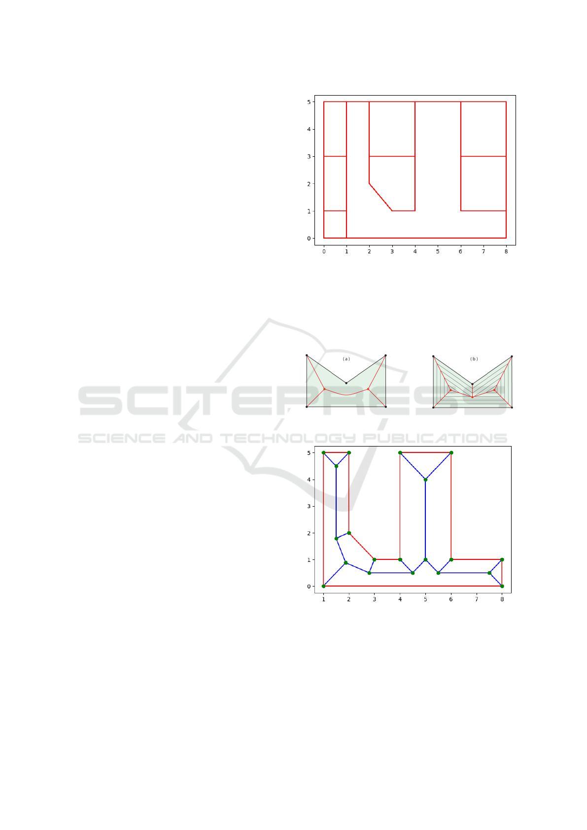
gons, like the indoor map of Figure 1.
Let us consider the difference between the medial
axis and the straight skeleton. Both are algorithms
that allow us to extract a representative linear object
from a planar shape. The medial axis of a polygon
is defined as the place of the points within the poly-
gon which have equal distance from more than one
point of the boundary. If a polygon is non-convex,
the medial axis has curved parts in correspondence
of non-convex vertices of the polygon. To avoid this
difficulty, it is possible to consider the straight skele-
Figure 1: Case study.
ton. The latter is defined as the trace of vertices when
a progressive shrinking of the polygon is performed.
The two definitions coincide for convex polygons and
mark a difference for non-convex polygons, as shown
in Figure 2.
Figure 2: Differences between medial axis (a) and straight
skeleton (b).
Figure 3: Skeletonized non-convex polygon.
Straight skeletons can be more easily implemented
both from the algorithmic point of view and from the
necessary data structures. Figure 3 clearly shows the
effect after applying the algorithm on a non-convex
polygon of our case study map. Storing the results
derived from the application of the straight skeleton
algorithm requires a suitable data structure, which we
The Construction of a Network for Indoor Navigation
255
identify as an undirected graph weighed on the Eu-
clidean distance between the nodes, for which we
used a Python3 library called “networkx”.
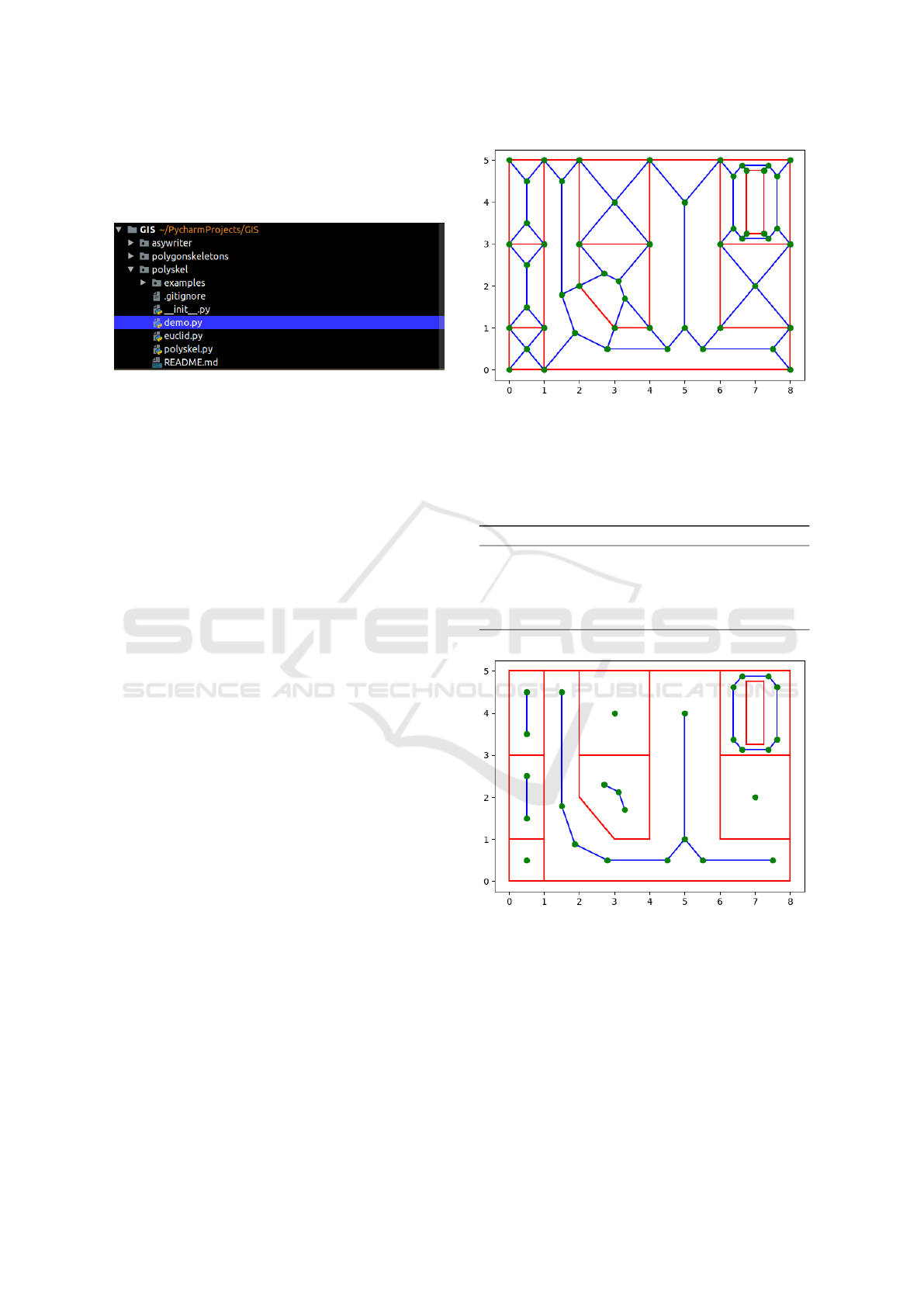
Figure 4: Straight skeleton package organization.
We used an open-source solution of the straight
skeleton (github project: https://github.com/Botffy/
polyskel.git), which represents a Python3 implemen-
tation of the algorithm by (Felkel and Obdr
ˇ
z
´
alek,
1998). Such a package (Figure 4) is organized as fol-
lows:
• demo.py is a main program that imports the
points to describe a polygon and its internal holes.
This information is enclosed in an external file and
imported when it is run.
• skeleton.py is the class that contains all the func-
tions that describe the straight skeleton algorithm.
• euclid.py is a basic Euclidean geometry library
that is used to instantiate objects such as points
and segments and perform intersection and con-
nection operations between them.
We applied the algorithm to the scenario of Figure 1,
after having inserted some holes to simulate the pres-
ence of objects inside the rooms and understand how
the algorithm behaved in this situation. The algorithm
was applied separately to each polygon, obtaining a
set of graphs that represent the skeletonized rooms
(see Figure 5).
3 INSERTING POINTS OF
INTEREST
In this section, we describe two aspects: the elimina-
tion from the graphs of uninteresting points for navi-
gation, such as the room vertices, and the insertion of
semantically rich points, such as the doors.
3.1 Graph Simplification
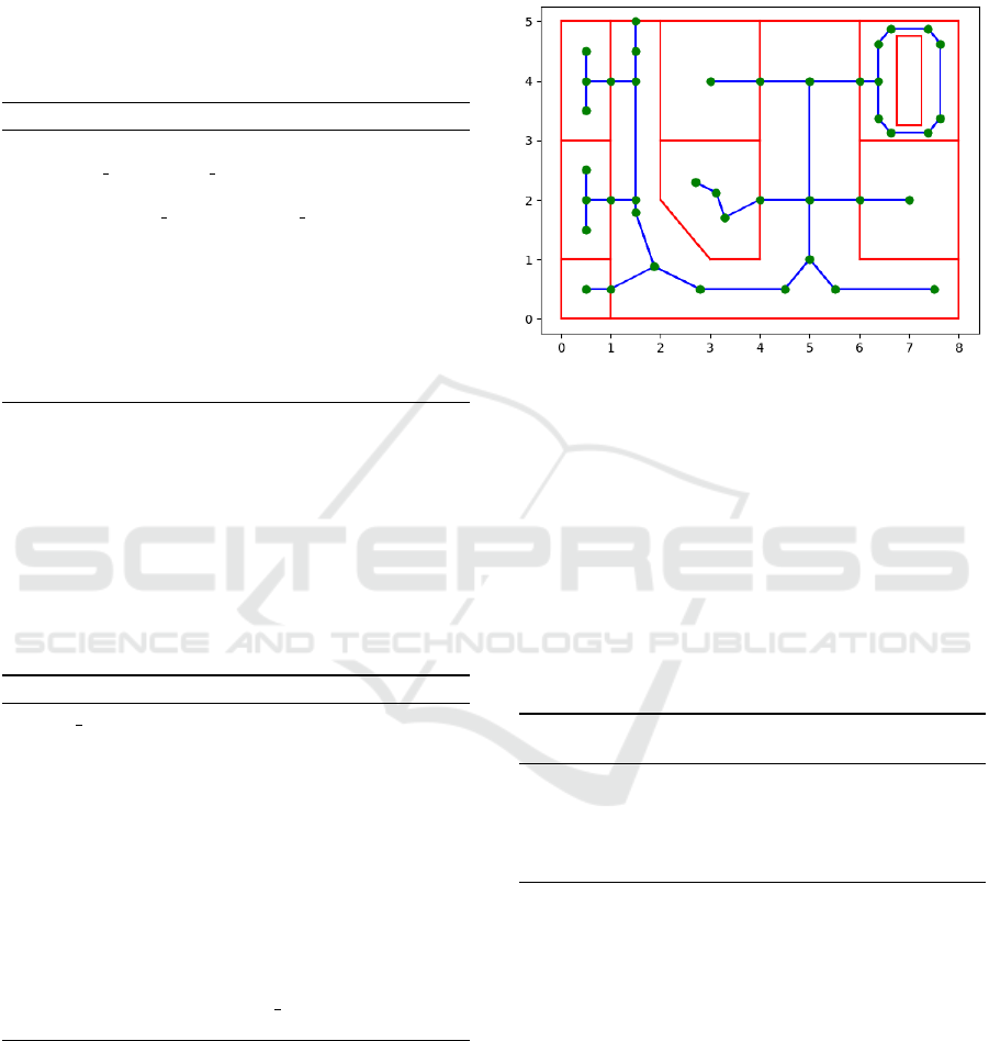
For navigability, it is not necessary to reach the cor-
ners of rooms. So we can eliminate the unnecessary
vertices from the graphs by eliminating from each
Figure 5: Straight skeletons of all rooms.
graph the nodes with only one incoming arc, that is,
the leaves of the graph (Algorithm 1). The result of
the simplification is shown in Figure 6, where each
room has its simplified graph.
Algorithm 1: Reduce graph of straight skeleton.
1: for node in graph.nodes do
2: if node.degree is < 2 then
3: delete node from the graph
4: end if
5: end for
Figure 6: Simplified graphs.
3.2 Inserting Access Points
To this point, we have a set of separate graphs for each
room deriving from the straight skeleton. To allow
the transition from one room to another, we need to
add a connection between the two graphs of adjacent
rooms. We build each connection with a central node
(defined from now on as a door node) connected to the
graphs by means of two arcs. Connecting the rooms
GISTAM 2020 - 6th International Conference on Geographical Information Systems Theory, Applications and Management
256
is important to apply a search algorithm for the short-
est paths between a source and a destination node be-
longing to different rooms. To facilitate and improve
the management of information that allows us to un-
derstand which rooms are connected via that door, we
define a matrix called the room-door connection ma-
trix. This matrix is composed by a door node for each
row by and a room for each column.
Algorithm 2: Construction of room-door connection matrix.
1: matrix=[]
2: for door node in door nodes do
3: row=[]
4: for polygon room in polygon rooms do
5: if room intersects door then
6: add true in row
7: else
8: add False in row
9: end if
10: end for
11: add row to matrix
12: end for
Starting from a list of door nodes, we calculate if a
door intersects a given room and populate the matrix
row by row (Algorithm 2). Therefore, in each row
of the matrix, there will no more than two matches,
since the only cases that can occur are those in which
a door belongs to a single room (external door) or two
rooms (internal door). On the other hand, in each col-
umn, we can observe the number of doors connecting
a room.
Algorithm 3: Construction of the door paths.
1: door paths=[ ]
2: for graph room that matches adjacency matrix do
3: conn distance edges vector
4: for edge in graph do
5: find the minimum distance from the door and
the edge and add to conn
6: end for
7: take the edge with minimum distance from conn
and build a new edge that connects this one with the
door
8: if vertex u or v of edge are not in graph then split
edge
9: end if
10: the result is added to door paths
11: end for
Algorithm 3 allows us to obtain the door paths, that
is, the pairs of arcs that have doors as the central node
and that connect graphs of two different rooms. This
algorithm creates the arcs that connect a door node to
graph rooms. For each door, the algorithm looks for
the closest point between all the arcs of the matching
graph. If the closest point is a node of the graph, the
connection is simpler. If the closest point falls inside
an arc, then it is necessary to split the arc into two
shorter arcs. The results of the application of the op-
erations just mentioned are visible in Figure 7.
Figure 7: Graph with door paths.
3.3 Association of Nodes to Rooms
When joining all the single graphs with the paths on
the newly calculated door nodes, it is necessary to
keep trace of the room every node belongs to. The
door nodes are already represented in the previously
mentioned matrix, where they belong to two rooms.
For the nodes inside the rooms, Algorithm 4 iterates
over each graph and check the nodes by attributing to
each of them the identification number of its room.
Algorithm 4: Function to add information about node mem-
bership.
1: for graph in graphs do
2: for node in graph.nodes do
3: add in node info about the membership room
4: end for
5: end for
4 SMOOTHING SHARP ANGLES
The straight skeleton algorithm for polygons with in-
ternal angles greater than 270
◦
leads to linear shapes
with sharp turning angles, like in the case of Figure 8.
It is for this kind of situations that the straight skeleton
algorithm deviates from the medial axis. In this sec-
tion, we adopt a strategy of “cutting” the vertices in
correspondence of internal angles greater than 270
◦
.
Algorithm 5 identifies the vertices to be cut. Each
identified vertex is substituted in the room boundary
by two vertices at a small distance. In Figure 8 and
The Construction of a Network for Indoor Navigation
257
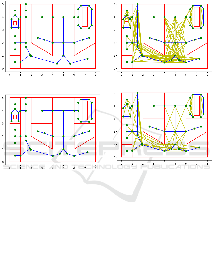
Figure 8: The network before the application of function to
smooth sharp vertices.
Figure 9: The network after the application of function to
smooth sharp vertices.
Algorithm 5: Function to smooth angle.
1: procedure AnglePolygonSmooth(rooms,c)
2: for room in rooms do
3: for poly in room do
4: for incremental triple of vertex do
5: compute the angle between them
6: if internal angle is > 270 degrees then
needs to be cut
7: end if
8: end for
9: end for
10: end for
11: end procedure
Figure 9, it is possible to compare the map before and
after the application of this algorithm, with the choice
of a very small factor for cutting the sharp vertex. In
such a figure, it is difficult to notice the removal of
the vertex and its substitution with two extra vertices,
but the change in the straight skeleton is evident and
qualitatively more appealing for navigation.
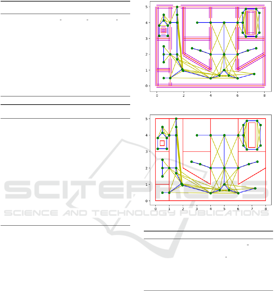
Figure 10: Overlay with visibility graph.
Figure 11: Visibility graph after removal of intersections.
5 ADDING VISIBILITY GRAPH
As explained in the introduction, in our strategy we
combine straight skeletons with visibility graphs. By
connecting nodes that are in clear visibility, we obtain
shorter paths that mimic the behaviour of other cat-
egories of navigation algorithms. Therefore, we use
the network nodes already found in previous section
and we compute the visibility graph based on these
nodes. Algorithm 6 allows the creation of the visibil-
ity graph (see Figure 10).
After the visibility graph is obtained, we reduce
the number of arcs by eliminating the arcs that in-
tersect with existing arcs of the initial network (see
Figure 11). The intersection between a point and a
line necessary in Algorithm 6 was obtained with Al-
gorithm 7. The latter calculates the collinearity be-
tween a point and a segment via a cross product.
GISTAM 2020 - 6th International Conference on Geographical Information Systems Theory, Applications and Management
258
Algorithm 6: Function that checks the visibility between
two nodes.
1: procedure visibility check( first node,second node,
room)
2: intersection = False
3: for wall in room do
4: if wall intersects segment composed by first
node and second node then
5: intersection = True
6: end if
7: end for
8: if intersection is False then append edge to the vis-
ibility graph
9: end if
10: end procedure
Algorithm 7: Function to compute intersection between
Point and Segment.
1: function IntersectionBetweenPointandSegment(P,S)
2: M =
S.p1.x S.p1.y 1
S.p2.x S.p2.y 1
P.x P.y 1
3: if det(M) = 0 then collinearity test
4: D(S.p1, S. p2) distance between S.p1 and
S.p2
5: if D(S.p1, P) < D(S.p1, S. p2) and D(S.p2, P) <
D(S.p1, S. p2) then
6: return True
7: else
8: return False
9: end if
10: else
11: return False
12: end if
13: end function
6 NETWORK BUFFERIZATION
A problem of a navigation network based on visibility
is that produces links that are too much close to walls.
As a final phase of the network construction, we avoid
such a problem by applying an inward buffer to the
polygons that make up the building plan and then re-
moving the links that intersect the buffer.
The width of the buffer can be chosen depending
on the extension of the room: therefore, we make it
dependent from the apothem of each polygon. The
implementation of the buffer for our study case has
been made by translating each segment representing
a wall by the chosen width and connecting them by
circular arcs centered on segment endpoints. Then, a
method has been added to verify the intersection with
navigation network. The doors between rooms have
not been bufferized. The application of the method
just discussed on the visibility graph is visualized in
Figure 12.
Figure 12: Bufferization of the rooms.
Figure 13: Final graph.
Algorithm 8: Function to filter not connected elements.
1: procedure FilterNotConnected(principal node)
2: for node in graph.nodes do
3: if Dijkstra from principal node to node outputs
not achievable then
4: delete node
5: end if
6: end for
7: end procedure
It can be seen seen that in this graph there are several
eliminations of previous arcs. During this process, it
can happen that the elimination of some arcs caused
the disconnection of graph components making the
graph no longer connected. To verify the reachability
of all the nodes of the graph, we choose a main node
(which could be for example the entrance of the build-
ing) and apply Dijkstra from the main node to other
nodes. If reachability is not verified, those nodes will
be eliminated making the graph connected again. This
function is represented in Algorithm 8. Normally,
choosing a thin buffer does not provoke the interrup-
The Construction of a Network for Indoor Navigation
259
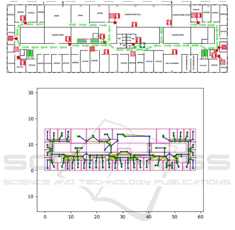
Figure 14: Emergency plan of university floor.
Figure 15: Navigation network for university floor.
tion of the navigation graph. Therefore, this action
can be useful if from the main entrance the navigating
agent has a considerable size and we want to discard
the parts of the map where the agent does not fit. In
Figure 13, there is the final navigation network for the
case study.
7 CONCLUSIONS
In this paper, we proposed the automatic construction
of a navigation network for the map of a typical build-
ing floor. While there are several proposals in the lit-
erature (e.g., (Lee, 2004; Taneja et al., 2011; Mortari
et al., 2019)), there are recognized drawbacks in each
proposal. In our contribution, we try to overcome all
the drawbacks. We start from computing the straight
skeleton of the map and combine it with a visibility
graph over the straight skeleton nodes. We believe
that this approach interprets a good qualitative model-
ing of the movement of people inside an indoor envi-
ronment, obtaining a smooth path at the center of cor-
ridors and around vertices and finding shorter paths
on larger halls based on visibility. Semantic aspects
have been introduced to keep trace of rooms and doors
connecting them. An inward bufferization can also
avoid movements too close to walls and solve naviga-
tion planning for sizeable agents (e.g., for people with
reduced mobility).
GISTAM 2020 - 6th International Conference on Geographical Information Systems Theory, Applications and Management
260

At the time of writing, we started an evaluation of
the algorithm for some real building floors. In Fig-
ure 14, we took into consideration an emergency map
of a floor in our university and we applied the algo-
rithm to find the navigation network for this map: the
result is shown in Figure 15. Further work will follow
in several research directions. To validate the shape
of the network, we plan to collect various trajecto-
ries of moving people inside a building instructing
them to walk from the entrance to a given target and
compare their trajectories with the proposed naviga-
tion network to assess if it could be considered as the
representation of the average trajectory. Another de-
velopment is to find an automatic way of extracting
qualitative directions for moving inside the building
floor, similarly to the work of (Russo et al., 2014).
Directions should not be expressed in terms of angles
and metric distances, but in qualitative terms, making
use of various models for qualitative spatial reason-
ing (e.g., (Clementini, 2013; Fogliaroni and Clemen-
tini, 2015; Bartie et al., 2013; Clementini and Cohn,
2014; Tarquini and Clementini, 2008)). An extension
of the proposed network is necessary as well to con-
nect building floors among them via stairs or elevators
and with outdoor space.
REFERENCES
Bartie, P., Clementini, E., and Reitsma, F. (2013). A quali-
tative model for describing the arrangement of visible
cityscape objects from an egocentric viewpoint. Com-
puters, Environment and Urban Systems, 38(1):21–
34.
Clementini, E. (2013). Directional relations and frames of
reference. GeoInformatica, 17(2):235–255.
Clementini, E. and Cohn, A. (2014). RCC*-9 and CBM*.
In Duckham, M., Pebesma, E., Stewart, K., and Frank,
A., editors, GIScience 2014: Geographic Information
Science, volume 8728 of Lecture Notes in Computer
Science, pages 349–365, Cham. Springer.
Fallah, N., Apostolopoulos, I., Bekris, K., and Folmer, E.
(2013). Indoor human navigation systems: A survey.
Interacting with Computers, 25(1):21–33.
Felkel, P. and Obdr
ˇ
z
´
alek, S. (1998). Straight skeleton imple-
mentation. In Szirmay-Kalos, L., editor, Proceedings
of Spring Conference on Computer Graphics, pages
210–218, Budmerice, Slovakia.
Fogliaroni, P. and Clementini, E. (2015). Modeling visi-
bility in 3D space: A qualitative frame of reference.
In Breunig, M., Al-Doori, M., Butwilowski, E., Ku-
per, P., Benner, J., and Haefele, K., editors, 9th Inter-
national 3DGeoInfo Conference, 2014, Lecture Notes
in Geoinformation and Cartography, pages 243–258,
Cham. Springer.
Fu, M., Liu, R., Qi, B., and Issa, R. R. (2020). Generating
straight skeleton-based navigation networks with in-
dustry foundation classes for indoor way-finding. Au-
tomation in Construction, 112:103057.
Kolbe, T., Gr
¨
oger, G., and Pl
¨
umer, L. (2005). CityGML:
Interoperable access to 3D city models. In van Oost-
erom, P., Zlatanova, S., and Fendel, E., editors, Geo-
information for Disaster Management, pages 883–
898, Berlin, Heidelberg. Springer.
Lee, J. (2004). A spatial access-oriented implementation of
a 3D GIS topological data model for urban entities.
GeoInformatica, 8(3):237–264.
Montello, D. R. (1993). Scale and multiple psychologies of
space. In Frank, A. U. and Campari, I., editors, Spa-
tial Information Theory A Theoretical Basis for GIS,
pages 312–321, Berlin, Heidelberg. Springer.
Mortari, F., Clementini, E., Zlatanova, S., and Liu, L.
(2019). An indoor navigation model and its network
extraction. Applied Geomatics, 11(4):413–427.
Russo, D., Zlatanova, S., and Clementini, E. (2014). Route
directions generation using visible landmarks. In 6th
ACM SIGSPATIAL International Workshop on Indoor
Spatial Awareness, ISA 2014, pages 1–8, New York,
NY, USA. Association for Computing Machinery.
Taneja, S., Akinci, B., Garrett, J. H., and Soibelman, L.
(2016). Algorithms for automated generation of nav-
igation models from building information models to
support indoor map-matching. Automation in Con-
struction, 61:24 – 41.
Taneja, S., Akinci, B., Garrett, J. H., Soibelman, L., and
East, B. (2011). Transforming IFC-based building
layout information into a geometric topology network
for indoor navigation assistance. In International
Workshop on Computing in Civil Engineering 2011,
pages 315–322. American Society of Civil Engineers
(ASCE).
Tarquini, F. and Clementini, E. (2008). Spatial relations
between classes as integrity constraints. Transactions
in GIS, 12(SUPPL. 1):45–57.
van Toll, W., Cook Iv, A. F., van Kreveld, M. J., and Ger-
aerts, R. (2018). The medial axis of a multi-layered
environment and its application as a navigation mesh.
ACM Transactions on Spatial Algorithms and Sys-
tems, 4(1):1–21.
Wein, R., van den Berg, J. P., and Halperin, D. (2007).
The visibility–Voronoi complex and its applications.
Computational Geometry, 36(1):66 – 87.
Yang, L. and Worboys, M. (2015). Generation of naviga-
tion graphs for indoor space. International Journal of
Geographical Information Science, 29(10):210–218.
Yao, C. and Rokne, J. (1991). A straightforward algorithm
for computing the medial axis of a simple polygon. In-
ternational Journal of Computer Mathematics, 39(1-
2):51–60.
Zlatanova, S., Yan, J., Wang, Y., Diakit
´
e, A., Isikdag,
U., Sithole, G., and Barton, J. (2020). Spaces in
spatial science and urban applications—state of the
art review. ISPRS International Journal of Geo-
Information, 9(1):58.
The Construction of a Network for Indoor Navigation
261
