
Analysis of Different Human Body Recognition Methods and Latency
Determination for a Vision-based Human-robot Safety Framework
According to ISO/TS 15066
David Bricher
a
and Andreas M
¨
uller
b
Institute of Robotics, Johannes Kepler University, Altenbergerstraße 69, 4040 Linz, Austria
Keywords:
Human-robot-collaboration, Latency Determination, ISO/TS 15066, Deep Learning, Human Recognition,
Body Part Recognition, HRC Safety Standard.
Abstract:
Today, an efficient and flexible usage of lightweight robots in collaborative working spaces is strongly limited
by the biomechanical safety regulations of ISO/TS 15066. In order to maximize the robot performance without
contradicting the technical standards and recommendations, a safety framework is introduced, which makes
use of state-of-the-art deep learning algorithms for human recognition and human body part identification.
Particularly, a generic vision-based method for the determination of the occurring latencies is proposed. To
this end, the different latency contributions from the recognition process up to the process of adapting the
robot speed to an ISO-conform level are analyzed in detail.
1 INTRODUCTION
In the last decade the field of collaborative robotics
received growing interest in industrial research. In
contrast to traditional robotic machines, collabora-
tively operating robotic systems do not necessarily re-
quire the installation of safety facilities which phys-
ically separate the working environment of humans
and robots (e.g. safety fences).
Therefore, collaborating robots are controlled and
designed in such a way that potential collisions be-
tween human and robots do not cause physical harm.
Since these collisions may appear in any (even un-
foreseeable) situation, it is obligatory to carry out a
hazard identification with corresponding risk assess-
ment before installing a robotic system and adjusting
its safety related parameters (e.g. robot velocity). The
safety requirements for the use of industrial collabora-
tive robot systems are laid down in the technical spec-
ification ISO/TS 15066 (ISO/TS 15066, 2016) and
describe the maximally allowed transient and quasi-
static contact forces and pressures occurring in a col-
lision. These force and pressure limits highly depend
on the body region that most likely tends to collide
with the robot.
In order to implement these guidelines, it is neces-
a
https://orcid.org/0000-0002-8335-2874
b
https://orcid.org/0000-0001-5033-340X
sary to determine which body parts might get in con-
tact with the robot in any possible way. The body
region with the lowest allowed force and pressure
level then defines the maximally allowed robot veloc-
ity. This fact is one of the biggest obstacles in using
collaborating systems in a flexible and efficient man-
ner. Whenever an essential change of the collabora-
tive use case or the environment occurs, a new risk as-
sessment has to be carried out which possibly means
a further adaptation of the maximally allowed robot
speed. Thus, it is an important step for the applicabil-
ity of human robot collaborating environments, if one
could dynamically evaluate which human body part
will collide with the robot most likely.
In this paper the concept of a dynamic safety
framework is introduced which detects the presence
of humans in the working environment of a robot
system. In the field of vision-based safety monitor-
ing different approaches have been investigated in or-
der to avoid collisions for human-robot-collaboration,
e.g. (Tan and Arai, 2011), (Bdiwi et al., 2017), (Ryb-
ski et al., 2012) or (Campomaggiore et al., 2019). The
presented analysis focuses on different state-of-the-
art machine learning algorithms that are applied on
RGB-D sensor data. Within the proposed prototyp-
ical safety framework, the human body part which
is closest to the robot’s tool center point (TCP) is
determined. This shall enable an efficient exploita-
Bricher, D. and Müller, A.
Analysis of Different Human Body Recognition Methods and Latency Determination for a Vision-based Human-robot Safety Framework According to ISO/TS 15066.
DOI: 10.5220/0009446403690376
In Proceedings of the 17th International Conference on Informatics in Control, Automation and Robotics (ICINCO 2020), pages 369-376
ISBN: 978-989-758-442-8
Copyright
c
2020 by SCITEPRESS – Science and Technology Publications, Lda. All rights reserved
369

tion of robotic facilities and thus a more flexible op-
eration of collaborating systems in changing work-
ing environments respecting the relevant safety stan-
dards. To ensure reliability, a vision-based method
for the determination of the time difference between
the recognition of humans, respectively human body
parts, within the working environment and the point
in time, when the robot control adjusts its speed, is
introduced. With the knowledge of the occurring la-
tencies the robot’s velocity can be adjusted dynami-
cally in accordance with the ISO standard. All of the
presented experimental results were conducted on a
KUKA iiwa 7-DOF lightweight robot.
2 HUMAN RECOGNITION
The recognition of predefined objects (e.g. humans)
in images has been one of the main challenges in the
field of computer vision. Typical object recognition
algorithms can be divided into the extraction of object
specific features and their classification. In order to
assess the collision potential of a specific human body
part with a robot, a robust and accurate recognition of
the human body is crucial.
2.1 Deep Learning Methods
Though typical methods in computer vision like Haar
cascade algorithms (Viola and Jones, 2004) or HOG
based approaches (Dalal and Triggs, 2005) are ad-
vantageous for human detection because of the low
computational effort, they are prone to misdetections,
failed and duplicate detections.
In the last few years different deep learning ap-
proaches were shown to outperform state-of-the-art
image processing algorithms for the task of iden-
tifying humans respectively particular human body
parts. Within the proposed framework the following
approaches are analysed:
• Human body recognition - SSD MobileNet
(Huang et al., 2017)
• Human body segmentation - Mask R-CNN (He
et al., 2017)
• Human pose estimation - Deep Pose (Toshev and
Szegedy, 2014)
• Human body part segmentation - Human body
part parsing (Fang et al., 2018).
It is, however, necessary to interpret this 2D informa-
tion in the 3D context, as discussed next.
2.2 Extraction of Depth Information
In order to extract the depth information of the de-
tected humans, the safety framework makes use of
an RGB-D camera with infrared stereo depth tech-
nology. The software architecture of the camera (In-
tel RealSense) offers the possibility to align the taken
RGB image with the information of the depth sensor,
i.e. the corresponding depth information can be as-
signed to every pixel in the RGB image.
The determination of the body part, which is clos-
est to the camera, follows a very restrictive approach:
All depth values within the bounding box or within
the semantic silhouette are evaluated and the smallest
depth value is extracted as
d
min
= min d(x,y),
(1)
with x and y being coordinates in the image plane, and
d(x, y) is the depth assigned to the image point (x, y).
Consequently, for human recognition and human seg-
mentation it is only possible to conclude which body
point is closest to the robot. On the other hand, hu-
man pose estimation and human body part segmen-
tation offer the possibility to determine the minimal
distance to the robot for each individual body part.
Accordingly, this simple approach can be used for a
dynamical adaption of the robot speed depending on
the separation distance between human and robot.
3 SAFETY ASPECTS
In the framework proposed in this paper, the speed of
the robot is reduced within the pre-collision phase al-
ready. The strategy is to adjust the speed according
to the distance between robot and human. This may
not avoid collisions but rather ensures safe contact
conditions (according to ISO/TS 15066) at any time
which is key to an efficient operation of the collabo-
rate robotic system. Thus, the information about the
identified human body parts and their spatial position
must be related to the core points of ISO/TS 15066.
The technical specification lays down four different
methods of collaborative operation:
a) safety-rated monitored stop
b) hand guiding
c) speed and separation monitoring
d) power and force limiting.
This paper addresses methods c) and d). According
to ISO/TS 15066, when operating in method c), the
robot system initiates a stop when the operator is com-
ing closer to the robot than allowed by the prescribed
ICINCO 2020 - 17th International Conference on Informatics in Control, Automation and Robotics
370

separation distance. In method d), the robot veloc-
ity is limited according to the body part that is near-
est to the robot. Neither of both operation methods
admits economically efficient human-robot collabora-
tion. Aiming at an economically efficient solution that
respects the safety regulations, the concept of a col-
laboration framework is proposed in this paper com-
bining operation methods c) and d). To this end, the
robot velocity is adapted according to the body part
closest to the robot TCP (according to method c)) so
to ensure the power and force limitations (according
to d)).
At first, it is mandatory to guarantee, that the in-
stantaneous robot velocity will not lead to a viola-
tion of the force and pressure thresholds of ISO/TS
15066, i.e. to be in accordance with the regulations of
method d).
In order to exclude collisions while the robot ve-
locity is decreased to an ISO conform limit, it is nec-
essary to take into account the protective separation
distance between the operator and the robot, which is
described in method c) as
S
p
(t
0
) = S
h
+ S
r
+ S
s
+C + Z
d
+ Z
r
,
(2)
with S
p
(t
0
) being the protective separation distance
at current time t
0
. In the following the contributions
to the protective separation distance (2) are described
in more detail.
The contribution due to the operator’s motion is
given by
S
h
=
Z
t
0
+t
r
t
0
v
h
·dt ,
(3)
with t
r
being the reaction time of the robot system
and v
h
being the directed speed of humans within
the collaborative environment. Since the velocities
of humans (respectively of their body parts) cannot
be monitored with the investigated sensor technolo-
gies, a constant velocity of 1.6 m/s for separating dis-
tances > 0.5 m and 2.0 m/s for distances below 0.5
m according to ISO 13855 (ISO 13855, 2010) are as-
sumed.
S
r
is the contribution due to the robot’s reaction
time, i.e. the distance that arises due to the robot’s
movement towards or away from the human, starting
from the moment when a human comes too close to
the robot until the safety control system initializes a
stop. In the course of a more generic investigation
of the robot’s influence towards the separation dis-
tance, the planned robot path and the adjusted veloc-
ity profile have to be studied more carefully. When-
ever a change of maximal robot velocities occurs, the
velocity contribution towards or away from the hu-
man effects the separation distance. Subsequently, it
is mandatory to determine the influence of the veloc-
ity change within the robot’s reaction time. The in-
vestigated use case does not tend to have large robot
movements towards the human and therefore the in-
fluence of the robot motion is not studied within the
proposed analysis.
In the specification, the expression S
s
corresponds
to the distance the robot TCP travels after a halt
command has been issued until the robot has finally
stopped. As the proposed framework only takes into
account velocity adjustments and does not consider
the stopping of the robot, this term can be omitted in
the analysis.
The intrusion distance C is defined in ISO 13855
as the distance a part of the body can permeate the
sensing field before being detected. It is formulated
as
C = 8(d −14) ,
(4)
with d being the sensor detection capacity [mm].
Since no opto-electronic safety light-beam system
is used, this expression can be neglected within
the framework due to a sensor detection capac-
ity < 40 mm as well.
Finally, Z
d
and Z
r
are uncertainty contributions
corresponding to the position uncertainty of the op-
erator and the position uncertainty of the robot sys-
tem. In this paper these uncertainties are not ana-
lyzed quantitatively, but rather qualitative statements
are given and possible uncertainties of the estimation
of the human movement are considered.
Thus, the main focus of this analysis lies on the
consequences of the human motion for the needed
separation distances for an ISO compatible exploita-
tion of maximal robot velocities. As the specification
implies constant human velocities, the main parame-
ter which characterizes the separation distance is the
reaction time of the robot system t
r
.
4 LATENCY ANALYSIS
The main feature of the proposed framework proto-
type is the reduction of the robot velocity according
to the human body part closest to the robot. Since the
robot reaction to a human action will not be executed
instantaneously, the appearing reaction time t
r
must
be characterized carefully. In the following, the terms
reaction time t
r
and latency t
Lat
will be used synony-
mously.
In order to detect possible changes in the envi-
ronment a sensor system has to be used, which takes
some time t
Cap
to capture recent information from the
environment.
Accordingly, the gained information has to un-
dergo some processing steps with total processing
Analysis of Different Human Body Recognition Methods and Latency Determination for a Vision-based Human-robot Safety Framework
According to ISO/TS 15066
371
Operator
Light Bulb
3D Camera
PC
Robot &
Controller
Workpiece
ROI
Selection
Safety PLC
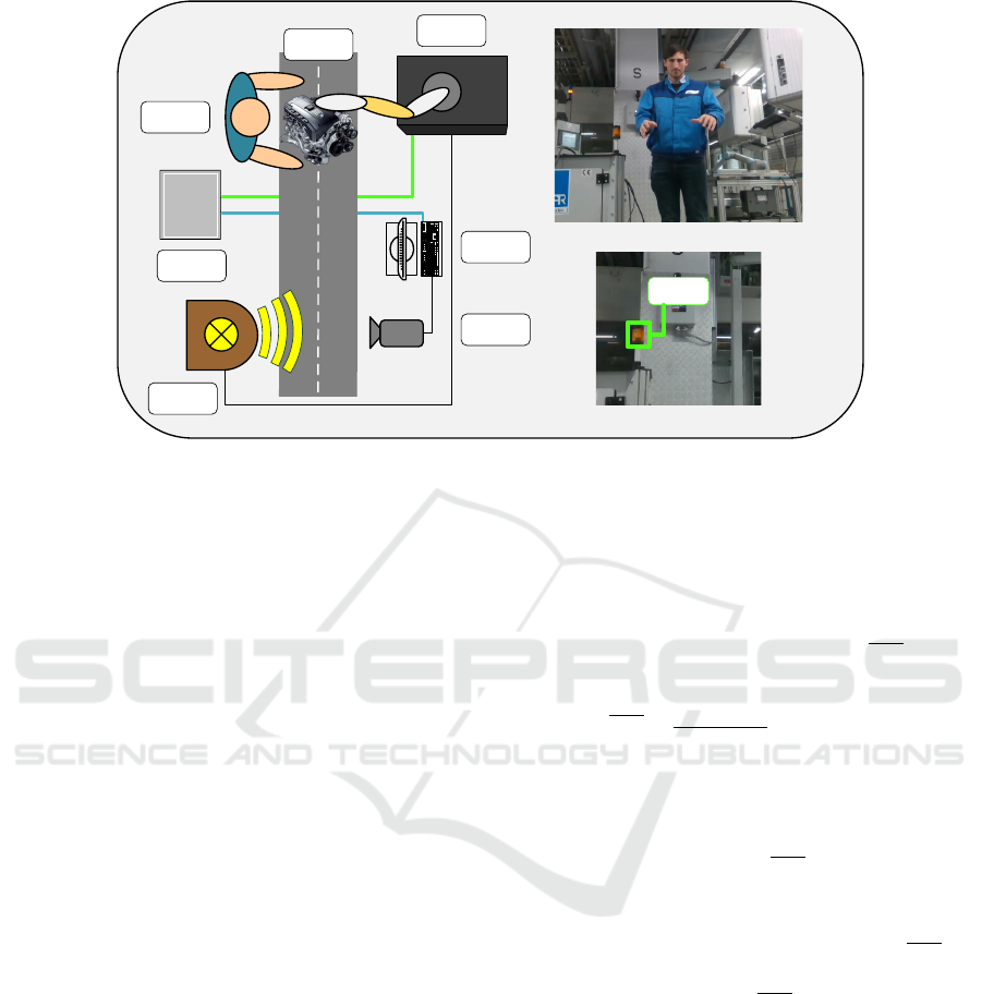
Figure 1: Left: Scheme of the measurement setup used for latency determination. Right: ROI selection before the latency
determination is started.
time t
Proc
in order to evaluate the situation in the con-
text. The total processing time of the analyzed use
case can be broken down into the time t
Alg
which cor-
responds to the time needed for the identification of
humans or specific human body parts and the time
needed for determining the depth information t
Depth
t
Proc
= t
Alg
+t
Depth
.
(5)
On the basis of the data processing the gained infor-
mation will be sent to the robot system in order to
initiate and execute an appropriate reaction. Thus, the
time t
Ad j
to adjust the velocity can be separated into
the time needed for the information exchange t
Com
and the robot reaction time t
Rob
t
Ad j
= t
Com
+t
Rob
.
(6)
Consequently, the latency t
Lat
can be introduced as
the sum of the above mentioned time periods
t
Lat
= t
Cap
+t
Proc
+t
Ad j
.
(7)
In the following, a method for the determination of the
latency within the safety framework is introduced.
4.1 Measurement Scheme
The human detection framework is running on a sep-
arate computing system and communicates via a net-
work protocol with the robot controller. Thus, two
different system operating clocks would have to be
synchronized before determining the latency. In order
to overcome this issue, the starting as well as the stop-
ping event are triggered on the robot controller. To
this end, the flashing of a light bulb (triggered from
the robot controller) is used as a starting signal.
Due to the fact that the camera view is static the
position of the light bulb is known. Before the ac-
tual human detection framework starts, a rectangular
region of interest (ROI) with width w
ROI
and height
h
ROI
can be selected, which encloses the light bulb.
Within the ROI the mean pixel intensity I
ROI
is deter-
mined, while the light bulb is turned off
I
ROI
=
1
h
ROI
·w
ROI
∑
y
∑
x
I(x, y) ,
(8)
where −w
ROI
/2 ≤ x ≤ w
ROI
/2 and
−h
ROI
/2 ≤ y ≤ h
ROI
/2. Furthermore, an inten-
sity threshold is introduced as
I
thres
= α ·I
ROI
,
(9)
with a predefined adjustable parameter α. The used
setup scheme is shown and explained in figure 1.
After capturing an image and depth frame,
I
ROI
can
be determined and is compared with I
thres
. The light
bulb flash is detected when I
ROI
> I
thres
. Within each
computation cycle an information block is transmit-
ted to the robot controller consisting of the following
entries:
• body region closest to camera [integer value]
• light bulb flash [boolean value]
• computation time of RGB and depth image cap-
turing t
Cap
[ms]
• computation time of chosen algorithm t
Alg
[ms]
(e.g. human detection, body region segmentation,
etc.)
• computation time of the depth estimation t
Depth
[ms].
ICINCO 2020 - 17th International Conference on Informatics in Control, Automation and Robotics
372

On the robot controller side two threads are running
in parallel on the following tasks:
• robot movement commands
• start and end trigger for latency determination (i.e.
the controller of the light source).
4.2 Experimental Setup
All of the shown experiments have been conducted on
a KUKA iiwa 7-DOF lightweight robot and the cor-
responding KUKA Sunrise Cabinet robot controller.
For the capturing of image and depth data an Intel Re-
alsense D435 RGB-D camera has been used. For the
sake of processing power comparison, all of the inves-
tigated deep learning algorithms have been analyzed
on three different computing modules:
• 2 core CPU - standard PC
• 640 core GPU - nvidia GeForce GTX 1050
• 1920 core GPU - nvidia GeForce GTX 1070.
In order to change the velocity of the robot during
its motion, the KUKA enhanced velocity controller
(EVC) package must be used. With this package it is
possible to activate different robot velocity limits in
the robot safety control which get activated with safe
input signals. For this reason the computing module
exchanges the body part information and the infor-
mation about the light bulb flash with a safety PLC
(via OPC UA protocol) beforehand. The PLC is pro-
grammed such that these information are transformed
into safe output signals and afterwards submitted to
the robot controller with a safe communication proto-
col (ProfiSafe).
The path planning process is executed as a sepa-
rate process on the robot controller, i.e. the user can
adjust an arbitrary path that the robot follows while
the latency measurement is being executed.
The latency determination is initiated by the robot
controller and can only be activated, when the robot
has reached its maximally allowed velocity. Then, the
starting trigger activates the light bulb. The first time
the message from the computing module indicates a
light bulb flash, the robot controller reduces the robot
velocity to the allowed minimum and turns off the
light bulb. At the same time, the stopping trigger fires
and the overall latency can be determined.
In order to investigate the additional computa-
tional costs of the analyzed algorithms when humans
are present in the sensing field, two testing scenarios
are considered - one, where no human is in the sens-
ing field of the camera and one with a human in the
sensing field. Each measurement has been conducted
for at least 5 minutes. The number of latency record-
ings per analyzed algorithm therefore depends of the
specific algorithm cycle times.
4.3 Determination of the Maximally
Occurring Latency
In order to estimate an upper bound on the latency
t
Lat−Max
, the point in time when the light bulb illumi-
nates must be related to the time frame of the image
processing. The two extreme cases for the beginning
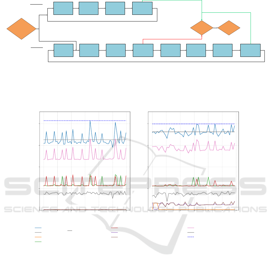
of the light bulb flash are illustrated in figure 2. As
shown in scenario A the lamp gets illuminated just be-
fore the image capturing process starts. Thereby, the
aforementioned process steps are executed only once
which leads to the minimal latency possible.
In contrast, scenario B shows the situation when the
light bulb flashing is initialized directly after the cap-
turing process. In this case all processing steps apart
from the image capturing are carried out twice which
leads to the maximal possible latency. The corre-
sponding processing time t
Proc
is
t
Proc
= t
Alg1
+t
Depth1
+t
Alg2
+t
Depth2
,
(10)
where t
Alg1
and t
Depth1
are the algorithm dependent
processing time and the depth determination time at
the first cycle, respectively, t
Alg2
and t
Depth2
at the sec-
ond cycle.
In order to guarantee safe switching of robot ve-
locities under any circumstances, the starting trigger
is initiated right after the image capturing process as
described in scenario B. Thereby, it is possible to ob-
tain an upper bound t
Lat−Max
on the latency for the
different analyzed deep learning algorithms.
5 EXPERIMENTAL RESULTS
As depicted exemplarily in figure 3, the final results
for all analyzed cases show, that the absolute la-
tency values strongly depend on the computing mod-
ule used. Especially modules with comparably low
computational power lead to strong fluctuations for
the processing time of the algorithm. This might be
explained by a strongly varying usage of the limited
computational resources.
Large fluctuations are observed for CPU-based
machines, while GPU-based computing modules ex-
hibit small latency fluctuations. Here, the contri-
butions for the algorithm processing mostly remains
constant over time and the fluctuations mainly appear
due to the varying adjustment time t
Ad j
, which is spe-
cific to the particular robot system used. For the used
KUKA iiwa robot controller the adjustment time t
Ad j
Analysis of Different Human Body Recognition Methods and Latency Determination for a Vision-based Human-robot Safety Framework
According to ISO/TS 15066
373
Start Latency
Determination
Send Information
to Robot Control
Processing Lamp
On/Off
Processing
Algorithm
Robot
Image Capturing
Stop
Latency
Scenario A:
Lamp On
Before
Image Capturing
Lamp On
Lamp On
Lamp Off
Send Information
to Robot Control
Processing Lamp
On/Off
Processing
Algorithm
Image Capturing
Send Information
to Robot Control
Processing Lamp
On/Off
Processing
Algorithm
Image Capturing
Scenario B:
Lamp On
After
Image Capturing
Figure 2: Influence of the point in time when the starting trigger fires. Scenario A: The light bulb flashes before the sensor
captures information from the environment - no additional processing steps necessary. Scenario B: The light bulb flashes after
the capturing process and is leading to additional processing steps before the information about the flashing lamp can be sent
to the robot control. This leads to fluctuations in the data processing time.
0 50 100 150 200 250 300
Time [s]
0
200
400
600
800
Delta Time [ms]
0 50 100 150 200 250 300
Time [s]
0
200
400
600
800
Delta Time [ms]
Human Body Segmentation - 1920 GPU cores
Latency t
Lat
Average Latency t
Lat
Capture t
Cap
Human Body Segmentation Algorithm 1 t
Alg1
Human Body Segmentation Algorithm 2 t
Alg2
Depth Determination 1 t
Depth1
Depth Determination 2 t
Depth2
Algorithm Computation t
Comp
Velocity Adjustment t
Adj
Maximal Latency t
Lat−Max
Figure 3: Latency determination for human body part segmentation (computation on 1920 GPU cores). Left: No human
within the camera’s field of view. Right: Humans enter sensing field.
is not known and cannot be measured directly. There-
fore, it is determined from the difference between
the measured latency t
Lat
and the computational time
t
Comp
which is composed of the capturing time t
Cap
and the processing time t
Proc
. From the experiment a
mean velocity adjustment time t
Ad j
of approximately
200 ms can be deduced which is expected to be inde-
pendent from the algorithms analyzed as well as for
all computing modules.
The minimally needed separation distance S
h
for
an ISO-conform switching of robot velocities can be
derived from the maximal algorithm dependent la-
tency t
Lat−Max
(considering the safety premises from
section 3). The corresponding results are given in ta-
ble 1 and show that the computation time strongly de-
pends on the chosen algorithm for human detection,
e.g. segmentation requires much more time than the
generation of human body joints. Besides the com-
putational time for the recognition process, the depth
determination is also more time demanding for human
body segmentation. The latter algorithms achieve a
more accurate recognition and depth estimation but
because of the large overall latency, they lead to larger
human separation distances. However, the compu-
tation time scales well with the computation power
(number of GPUs). These algorithms will be prefer-
able in the very near future, given the continuous in-
crease of computation power.
Furthermore, the results show that the algorithm
dependent recognition time is not influenced by hu-
mans present in the sensing field. Interestingly, the
fluctuations of t
Alg1
and t
Alg2
have a much bigger im-
ICINCO 2020 - 17th International Conference on Informatics in Control, Automation and Robotics
374

Table 1: Results obtained from the latency measurements using different methods for human detection and human body part
recognition. The mean latency, the maximally allowed latency as well as the deduced separating distance are all analyzed in
the presence and absence of humans in the sensing field of the camera.
Detection algorithm t
Lat
[ms] t
Lat
[ms] t
Lat−Max
[ms] t
Lat−Max
[ms] S
h
[m] S
h
[m]
2 core CPU without Human with Human without Human with Human without Human with Human
Bounding box 1043 802 1806 1531 2.89 2.45
Human pose estimation 1287 1167 1656 1412 2.65 2.26
Human body segmentation 12576 11091 14430 12798 23.09 20.48
Human body part segmentation 20860 18620 22091 20860 35.35 33.38
Detection algorithm t
Lat
[ms] t
Lat
[ms] t
Lat−Max
[ms] t
Lat−Max
[ms] S
h
[m] S
h
[m]
640 core GPU without Human with Human without Human with Human without Human with Human
Bounding box 557 561 637 642 1.02 1.03
Human pose estimation 318 342 347 392 0.56 0.63
Human body segmentation 922 1051 1085 1198 1.74 1.92
Human body part segmentation 1661 1770 1758 1847 2.81 2.96
Detection algorithm t
Lat
[ms] t
Lat
[ms] t
Lat−Max
[ms] t
Lat−Max
[ms] S
h
[m] S
h
[m]
1920 core GPU without Human with Human without Human with Human without Human with Human
Bounding box 273 301 311 326 0.50 0.52
Human pose estimation 198 223 224 249 0.36 0.40
Human body segmentation 415 499 461 552 0.74 0.88
Human body part segmentation 650 717 828 806 1.32 1.29
pact on the average and maximal latency estimation
than the computational time for the depth computa-
tion. This is the reason why sometimes higher latency
peaks can be observed when no human is in the sens-
ing field of the camera compared to the case when hu-
mans are positioned within the camera’s field of view.
Because the overall latency and thus also the
separation distance strongly depend on the available
computation power, human recognition processes can
only be processed with suitable GPU systems. By
using a standard 2 core CPU system, separating dis-
tances of about 30 meters would be required.
The results show that real-time human segmenta-
tion tasks can only be implemented by using compu-
tational systems with high GPU power, while for hu-
man detection and body pose recognition the compu-
tation power is not the limiting factor.
As the segmentation methods prove to be much
more robust and accurate than any other investigated
algorithm, separating distances below 1.5 meters be-
tween human and robot would be required. While
this is already in an acceptable range to allow ISO-
conform velocity switching, it will certainty be re-
duced in future given that the performance of the
recognition procedure scales well with the number of
GPU’s.
6 CONCLUSIONS AND FUTURE
WORK
This paper proposes a prototype for a safety frame-
work, which can be used for the dynamical adjust-
ment of the maximal speed of a collaborative robot
so that it does not violate the regulations of ISO/TS
15066. To this end, different deep learning algorithms
are investigated in order to detect humans respec-
tively their body parts in RGB-images. As a figure
of merit for the collision potential, the distance from
the robot’s TCP to the closest body part is chosen.
In order to guarantee a safe robot velocity switch-
ing, a generic method for the determination of the
occurring latency is proposed. The contributions of
different sources for latency are analyzed in detail
on three different computation modules for the cases
when a human is present or not. As demonstrated by
the results, the needed separating distance for a safe
adaption of robot speeds scales inverse to the num-
ber of GPU cores used (i.e. to the computational
power). Therefore, the increasing performance of to-
day’s graphics cards will soon enable a real-time iden-
tification of human body parts.
By introducing the framework in combination
with a safety-rated sensor technology, the proposed
Analysis of Different Human Body Recognition Methods and Latency Determination for a Vision-based Human-robot Safety Framework
According to ISO/TS 15066
375

concept allows a dynamical risk assessment and even-
tually enables a more flexible and efficient usage of
collaborative robot machines. Still there are several
open questions, which have to be studied more care-
fully before operating such a safety-framework in a
production environment:
• functional safety in connection with deep learning
algorithms
• handling of false identifications
• uncertainties in predicted positions
• unseen field of the sensing system and occlusion.
Eventually, it is anticipated that future safety regula-
tions will embrace the functionalities of future online
scene assessment methods as presented in this paper.
REFERENCES
Bdiwi, M., Pfeifer, M., and Sterzing, A. (2017). A new
strategy for ensuring human safety during various lev-
els of interaction with industrial robots. CIRP Annals,
66(1):453 – 456.
Campomaggiore, A., Costanzo, M., Lettera, G., and Natale,
C. (2019). A fuzzy inference approach to control robot
speed in human-robot shared workspaces. In Proceed-
ings of the 16th International Conference on Informat-
ics in Control, Automation and Robotics - Volume 2:
ICINCO,, pages 78–87. INSTICC, SciTePress.
Dalal, N. and Triggs, B. (2005). Histograms of oriented
gradients for human detection. In Proceedings of the
2005 IEEE Computer Society Conference on Com-
puter Vision and Pattern Recognition (CVPR) - Vol-
ume 1 - Volume 01, CVPR ’05, pages 886–893, USA.
IEEE Computer Society.
Fang, H.-S., Lu, G., Fang, X., Xie, J., Tai, Y.-W., and Lu,
C. (2018). Weakly and semi supervised human body
part parsing via pose-guided knowledge transfer. In
2018 IEEE/CVF Conference on Computer Vision and
Pattern Recognition, pages 70–78.
He, K., Gkioxari, G., Doll
´
ar, P., and Girshick, R. (2017).
Mask r-cnn. In 2017 IEEE International Conference
on Computer Vision (ICCV), pages 2980–2988.
Huang, J., Rathod, V., Sun, C., Zhu, M., Korattikara, A.,
Fathi, A., Fischer, I., Wojna, Z., Song, Y., Guadar-
rama, S., and Murphy, K. (2017). Speed/accuracy
trade-offs for modern convolutional object detectors.
In 2017 IEEE Conference on Computer Vision and
Pattern Recognition (CVPR), pages 3296–3297.
ISO 13855 (2010). Safety of machinery – positioning
of safeguards with respect to the approach speeds of
parts of the human body. Specification, International
Organization for Standardization, Geneva, CH.
ISO/TS 15066 (2016). Robots and robotic devices – collab-
orative robots. Technical specification, International
Organization for Standardization, Geneva, CH.
Rybski, P., Anderson-Sprecher, P., Huber, D., Niessl, C.,
and Simmons, R. (2012). Sensor fusion for human
safety in industrial workcells. In 2012 IEEE/RSJ In-
ternational Conference on Intelligent Robots and Sys-
tems, pages 3612–3619.
Tan, J. T. C. and Arai, T. (2011). Triple stereo vision system
for safety monitoring of human-robot collaboration in
cellular manufacturing. In 2011 IEEE International
Symposium on Assembly and Manufacturing (ISAM),
pages 1–6.
Toshev, A. and Szegedy, C. (2014). Deeppose: Human pose
estimation via deep neural networks. In 2014 IEEE
Conference on Computer Vision and Pattern Recogni-
tion, pages 1653–1660.
Viola, P. and Jones, M. J. (2004). Robust real-time face
detection. Int. J. Comput. Vision, 57(2):137–154.
ICINCO 2020 - 17th International Conference on Informatics in Control, Automation and Robotics
376
