
Application of Rodrigues Matrix in High Accuracy Geo-location for
ZY-3 Panchromatic Imagery
Xiaoming Gao
1
, Fan Mo
1, a
, Junfeng Xie
1
and Qijun Li
2
1
Land Satellite Remote Sensing Application Center, Ministry of Natural Resources, Beijing, China
2
Geospatial Information Institute, Information Engineer University, Zhengzhou, China
Keywords: Rigorous Geometric Model, Rodrigues Matrix, Constant Angular Error, Additional Parameters Model,
Bundle Adjustment.
Abstract: In this paper, Rodrigues matrix is proposed to establish constant angular error calibration model, and interior
orientation errors are compensated by additional parameters model. Bundle block adjustment model is
established by these two models on the basis of the rigorous geometric model for ZY-3 panchromatic imagery.
Once the constant angular errors and interior orientation errors are eliminated using a few GCPs, the geo-
location accuracy will be significantly improved.
1 INTRODUCTION
The Ziyuan-3 (ZY-3) surveying and mapping satellite
is the first civilian high-resolution satellite in China.
Its ground resolution of nadir-view camera is better
than 2.1 m, forward- and backward-view cameras are
better than 3.5 m, and multi-spectral camera is better
than 5.8 m. The main task of the ZY-3 satellite is
performing stereo mapping at a scale of 1: 50,000,
producing digital images, and updating topographic
maps at scales of 1 : 25,000 and larger, as well as
playing an important role in the fields of land
resources surveying and monitoring, agriculture,
disaster control, resources and environment, public
safety, etc. (Sun and Tang, 2009).
Multiple studies have been conducted on the ZY-3
mapping satellite. For example, Deren Li constructed
a geometric model for the imaging of the ZY-3
satellite and proposed an imaging technology based
on a virtual CCD linear array, that was used to
calibration (Li, 2012). Chubin Liu established a strict
geometric model for the stereoscopic location of the
panchromatic camera of the ZY-3 mapping satellite
(Liu, 2012). Dazhao Fan adopted a linearized euler
angle model to calibrate the constant error of the
attitude (Fan et al., 2013). Chubin Liu utilized a self-
calibrating method for the regional area adjustment of
the three-line array images (Liu et al., 2014).
Yonghua Jiang derived an internal orientation
a
https://orcid.org/0000-0002-5105-846X
calibration model for the CCD, and achieved a high
accuracy (Jiang et al., 2013). Finally, by analyzing the
direction angle of each CCD joint in the star sensor
coordinate system, Cao Jinshan proposed a direction
angle calibration method (Cao et al., 2014).
In this study, based on the strict imaging
geometric model of the ZY-3 satellite, we propose a
calibration model for the constant error of the attitude
angle using the Rodrigues rotation matrix. In
addition, by introducing an additional parameter
model considering the aberration to compensate for
the internal orientation distortion, we constructed a
block adjustment model using the self-calibrating
bundle method, that could derive the correction
numbers of both the internal and external orientation
elements based on a small number of ground control
points, then significantly improving the imaging geo-
location accuracy of the system.
2 STRICT GEOMETRIC MODEL
The strict geometric model utilized in this study for
the imaging of the ZY-3 mapping satellite can be
expressed by formula (1):
𝑋
𝑌
𝑍
𝑋
𝑌
𝑍
𝑚𝑅
𝑅
𝑡𝑎𝑛𝜑
𝑓
𝑡𝑎𝑛
𝜑
𝑓
𝑓
(1)
104
Gao, X., Mo, F., Xie, J. and Li, Q.
Application of Rodrigues Matr ix in High Accuracy Geo-location for ZY-3 Panchromatic Imagery.
DOI: 10.5220/0009434501040111
In Proceedings of the 6th International Conference on Geographical Information Systems Theory, Applications and Management (GISTAM 2020), pages 104-111
ISBN: 978-989-758-425-1
Copyright
c
2020 by SCITEPRESS – Science and Technology Publications, Lda. All rights reserved
where
𝑋
𝑌
𝑍
is the external orientation line
element; 𝑚 is the scale factor; 𝑅
is the rotation
matrix from the earth inertial coordinate system to the
earth-fixed reference coordinate system; and 𝑅
is
the rotation matrix from the body coordinate system
to the earth inertial coordinate system. 𝜑
and 𝜑
denote the direction angles.
Formula (1) shows that the external orientation
element in any row of images from the ZY-3 satellite,
which can be compensated in adjustment processing.
3 ATTITUDE ANGLE CONSTANT
ERROR CALIBRATION
As device installation, launching vibration,
environment change and other factors, there would
bring errors into the attitude and orbit data. If
unprocessed attitude, orbit data and the original
installation matrix of the satellite are used to restore
the imaging bundle based on the strict geometric
model, would resulting in substantial reduction in
geometric location accuracy. Therefore, correction of
the attitude constant angle error is very important for
satellite stereo geo-location accuracy, and block
adjustment (Yuan and Cao, 2012).
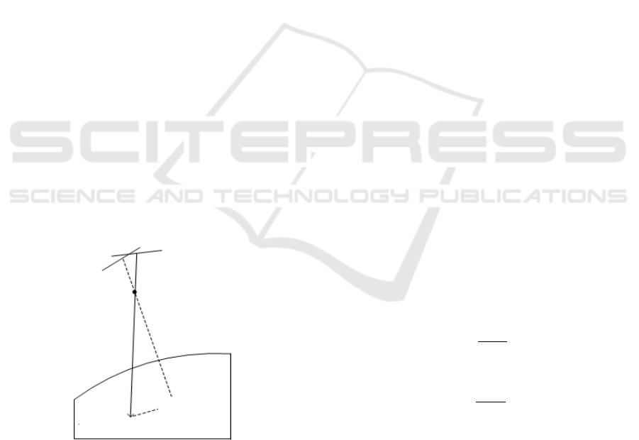
When the influence of atmospheric refraction is
excluded, the spatial geometric position of the
perspective center of the sensor and ground control
points can be utilized to accurately restore the
imaging bundle direction of the image point (Yuan
and Yu, 2008), as shown in Figure. 1.
Figure 1: Target geo-location error due to attitude angle
error.
3.1 Rodrigues Rotation Matrix
Suppose
𝑅
is an orthogonal rotation matrix with three
degrees of freedom, and
𝑆
is the anti-symmetric
matrix, then
𝑆
0𝑐𝑏
𝑐0𝑎
𝑏𝑎0
, where
𝑎
,
𝑏
, and
𝑐
are three independent unknowns.
𝑅
can be seen as a
Rodrigues rotation matrix composed of
𝑆
, which has
the following correlation:
𝑅
𝐼𝑆
𝐼𝑆
1𝑐𝑏
𝑐 1 𝑎
𝑏𝑎1
1𝑐𝑏
𝑐1𝑎
𝑏 𝑎 1
(2)
where 𝐼 is a 3rd order unit matrix.
3.2 Model Construction and Solution
As shown in Figure. 1, the constant error in the
attitude angle can be considered as an offset matrix 𝑅
between the actual imaging bundle and the ideal
imaging bundle. The strict geometric model is
corrected as follow:
𝑋
𝑌
𝑍
𝑋
𝑌
𝑍
𝑚𝑅
𝑅
𝑅
𝑡𝑎𝑛𝜑
𝑓
𝑡𝑎𝑛
𝜑
𝑓
𝑓
(3)
Suppose
𝑢
𝑅
𝑅
𝑋𝑋
𝑌𝑌
𝑍𝑍
(4)
𝑢
𝑅
𝑡𝑎𝑛𝜑
𝑓
𝑡𝑎𝑛
𝜑
𝑓
𝑓
(5)
𝑢
𝑢
‖
𝑢
‖
(6)
𝑢
𝑢
‖
𝑢
‖
(7)
By substituting 𝑅 into formula (3):
𝑢
𝑢
𝑢
1𝑐𝑏
𝑐 1 𝑎
𝑏𝑎1
1𝑐𝑏
𝑐1𝑎
𝑏 𝑎 1
𝑢
𝑢
𝑢
(8)
Pers
p
ective cente
r
Error bundle
Accurate
bundle
Real point
GCP
Application of Rodrigues Matrix in High Accuracy Geo-location for ZY-3 Panchromatic Imagery
105

𝑢
𝑢
𝑢
𝑢
𝑢
𝑢
0𝑢
𝑢
𝑢
𝑢
𝑢
𝑢
0𝑢
𝑢
𝑢
𝑢
𝑢
𝑢
0
𝑎
𝑏
𝑐
(9)
𝐴
0𝑢
𝑢
𝑢
𝑢
𝑢
𝑢
0𝑢
𝑢
𝑢
𝑢
𝑢
𝑢
0
(10)
𝐿
𝑢
𝑢
𝑢
𝑢
𝑢
𝑢
(11)
𝑋
𝑎
𝑏
𝑐
(12)
𝑉
𝐴
𝑋𝐿
(13)
As 𝑢
and 𝑢
are unit vectors, and only two out of
the three components are independent, only two
independent formulas can be listed for one ground
control point. Therefore, at least two control points
are required to obtain a solution using the least
squares method (Jia et al., 2012), so that the values of
𝑎, 𝑏, and 𝑐 can be derived to construct the offset
matrix 𝑅.
This model makes the offset matrix 𝑅 equal to the
Rodrigues parameters 𝑎, 𝑏, and 𝑐. They are resolved
linearly, and the non-linear constraint is solved by a
true linear method without compromising the
accuracy.
4 SELF-CALIBRATING BUNDLE
ADJUSTMENT
The geo-location accuracy is significantly improved
after compensation of the attitude angle by the
Rodrigues rotation matrix. However owing to an
internal orientation distortion, it still does not meet
the requirement for high-accuracy geo-location.
Therefore, the internal orientation element must be
calibrated. On the basis of the attitude angle constant
error calibration model using Rodrigues rotation
matrix, we introduced an additional parameter model
taking into account the aberration to compensate for
the internal orientation distortion. Based on the strict
geometric model, a self-calibrating bundle
adjustment model was constructed, which could
correct both the internal and external orientation
parameters.
4.1 Additional Parameter Model
Considering Aberration
The systematic error of a linear-array camera can be
roughly divided into an optical lens error and a CCD
linear array error. Similar to the perspective camera,
this systematic error is mainly composed of primary
point offsets, CCD rotation changes, and pixel size
variations (Lei, 2011). An additional parameter
model is constructed accordingly, as shown below:
⎩
⎪
⎨
⎪
⎧
∆𝑥
∆𝑥
𝑘
𝑟
𝑘
𝑟
𝑥
̅
𝑝
𝑟
2𝑥̅
2𝑝
𝑥̅𝑦𝑆𝑥̅
∆𝑦
∆𝑦
𝑘
𝑟
𝑘
𝑟
𝑦
𝑝
𝑥
̅
𝑦
2𝑝
𝑟
2𝑦
𝑅𝑥
̅
(14)
where ∆𝑥
and ∆𝑦
are the systematic correction;
∆𝑥
and ∆𝑦
are the offsets of the primary imaging
point; 𝑘
and 𝑘
are the radial distortion coefficients;
𝑝
and 𝑝
are the offset distortion coefficients; 𝑟 is the
radiant distance from the imaging point to the primary
point;
𝑥̅,𝑦
is the difference between the imaging
point coordinates and the primary point coordinates;
𝑆 is the scale factor; and 𝑅 is the rotation factor.
The additional parameter model taking into
account the aberration comprehensively considered
factors optical lens distortion, pixel size change and
CCD rotation variation. However, in actual
adjustments, different blocks present different
geometrical characteristics; therefore, the type and
number of additional parameters will affect the
stability of the model in obtaining a solution (Tang et
al., 2010; Gan and Yan, 2007). To prevent the
occurrence of a strong correlation between
parameters, the parameters of the additional
parameter model must be selected carefully during
adjustment.
4.2 Self-calibrating Bundle Adjustment
Model
Based on the strict geometric model, an improved
imaging geometric model that lays the foundation for
the bundle adjustment model is constructed by
comprehensively considering external orientation
compensation and internal orientation distortion as
shown
GISTAM 2020 - 6th International Conference on Geographical Information Systems Theory, Applications and Management
106

𝑋
𝑌
𝑍
𝑋
𝑌
𝑍
𝑚𝑅
𝑅
𝑅
𝑡𝑎𝑛𝜑
𝑓 ∆𝑥
𝑡𝑎𝑛
𝜑
𝑓∆𝑦
𝑓
(15)
In other words,
𝑅
𝑅
𝑋𝑋
𝑌𝑌
𝑍𝑍
𝑚𝑅
𝑡𝑎𝑛𝜑
𝑓∆𝑥
𝑡𝑎𝑛
𝜑
𝑓∆𝑦
𝑓
(16)
Suppose
𝑅
𝑅
𝑋𝑋
𝑌𝑌
𝑍𝑍
𝑋
𝑌
𝑍
̅
(17)
𝑥
𝑦
𝑧
𝑅
𝑡𝑎𝑛𝜑
𝑓
∆𝑥
𝑡𝑎𝑛
𝜑
𝑓∆𝑦
𝑓
(18)
We can therefore derive the collinear condition
formula:
𝑋
𝑍
̅
𝑦
𝑧
𝑌
𝑍
𝑦
𝑧
(19)
By calculating the derivatives of 𝑎, 𝑏, 𝑐 , ∆𝑥
,
∆𝑦
, 𝑘
, 𝑘
, 𝑝
, 𝑝
, 𝑆, and 𝑅, the above formula is
linearized, as shown below:
⎩
⎪
⎪
⎪
⎪
⎪
⎪
⎨
⎪
⎪
⎪
⎪
⎪
⎪
⎧
𝑉
𝜕𝑋
𝜕𝑎
d𝑎
𝜕𝑋
𝜕𝑏
d𝑏
𝜕𝑋
𝜕𝑐
d𝑐
𝜕𝑋
𝜕∆𝑥
d∆𝑥
𝜕𝑋
𝜕∆𝑦
d∆𝑦
𝜕𝑋
𝜕𝑘
d𝑘
𝜕𝑋
𝜕𝑘
d𝑘
𝜕𝑋
𝜕𝑝
d
𝑝
𝜕𝑋
𝜕𝑝
d𝑝
𝜕𝑋
𝜕𝑆
d𝑆
𝜕𝑋
𝜕𝑅
d𝑅 𝑙
𝑉
𝜕𝑌
𝜕𝑎
d𝑎
𝜕𝑌
𝜕𝑏
d𝑏
𝜕𝑌
𝜕𝑐
d𝑐
𝜕𝑌
𝜕∆𝑥
d∆𝑥
𝜕𝑌
𝜕∆𝑦
d∆𝑦
𝜕𝑌
𝜕𝑘
d𝑘
𝜕𝑌
𝜕𝑘
d𝑘
𝜕𝑌
𝜕𝑝
d
𝑝
𝜕𝑌
𝜕𝑝
d𝑝
𝜕𝑌
𝜕𝑆
d𝑆
𝜕𝑌
𝜕𝑅
d𝑅 𝑙
(20)
It can be expressed by matrix vectors as
𝑉
𝐴
𝑋𝐵𝑌𝐿
(21)
where 𝑋 is the Rodrigues rotation matrix parameter
vector, the corresponding coefficient matrix of which
is A. 𝑌 is the parameter vector of the additional model
that takes into account the aberration, the
corresponding coefficient matrix of which is B. 𝑉 is
the correction number vector; and 𝐿 is the observed
value vector.
5 EXPERIMENTS AND
ANALYSIS
5.1 Experimental Data
The experimental data used in this study were the
images, attached files, and ground control point data
of the ZY-3 mapping satellite acquired in the Hebei
Anping area on 2012-02-18 and the Liaoning Dalian
area on January 11, 2012. The Anping area had 70
ground control points, including 29 target ground
control points and 41 normal ground object control
points. The Dalian area had 19 ground control points,
all of which were normal ground object control
points. Most of the normal ground object control
points were located at road intersections for farmland
corners.
Application of Rodrigues Matrix in High Accuracy Geo-location for ZY-3 Panchromatic Imagery
107
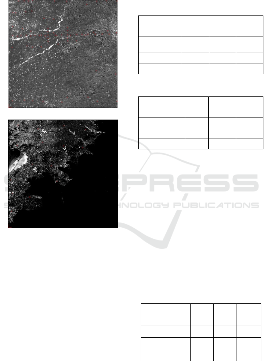
(a)
(b)
Figure 2: Control point distribution map, (a) Anping area
control point distribution map, (b) Dalian area control point
distribution map.
5.2 Rodrigues Rotation Matrix
Imaging Bundle Correction
Experiment
The geo-location accuracy statistics for the Anping
and Dalian areas, when the strict geometric model
was directly utilized for geo-location using the
auxiliary data, are listed in Tables 1 and 2.
Table 1: Unprocessed geo-location accuracy of the Anping
area.
Statistics Item X/m Y/m Z/m
Average error 220.136 437.579 824.830
Maximum
residual
225.107 515.886 845.053
Minimum residual
211.679 337.704 795.005
MSE 220.150 440.617 824.944
Table 2: Unprocessed geo-location accuracy of the Dalian
area.
Statistics Item X/m Y/m Z/m
Average error 77.199 623.378 603.520
Maximum residual
84.967 659.395 648.268
Minimum residual
73.497 563.374 530.545
MSE 77.253 624.164 604.618
It can be seen from Tables 1 and 2 that the geo-
location accuracy of the images in the Dalian area,
which was acquired earlier, was different from that of
the images in the Anping area. This is because, in the
early stage, the orbit of the satellite was not
completely stable, and the camera was still
performing a series of adjustments, which resulted in
changes in the external orientation attitude angle and
installation of the camera. Therefore, if unprocessed
auxiliary data acquired at different times are used
directly for geo-location, the accuracy of the geo-
location will be different.
Subsequently, a small number of uniformly
distributed ground control points were selected in the
Anping images, and the Rodrigues rotation matrix
was adopted to correct the imaging bundle. The
corrected imaging bundle was then used for geo-
location, with the resultant accuracy statistics
presented in Table 3.
Table 3: Geo-location accuracy of the Anping area after
imaging bundle correction.
Statistics Item X/m Y/m Z/m
Average error 3.971 1.761 4.108
Maximum residual
12.126 4.999 12.394
Minimum residual
0.124 0.233 0.120
Medium error 5.037 2.102 4.888
GISTAM 2020 - 6th International Conference on Geographical Information Systems Theory, Applications and Management
108
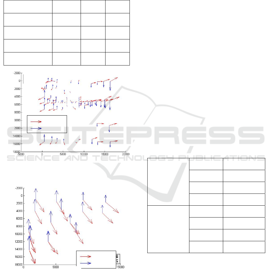
The Rodrigues rotation matrix parameters of the
Anping area were also used to perform extrapolative
geo-location of the Dalian area. The accuracy
statistics are listed in Table 4.
Table 4: Geo-location accuracy of the Dalian area by the
Rodrigues rotation matrix extrapolation.
Statistics Item X/m Y/m Z/m
Average error 13.057 34.493 27.700
Maximum residual
22.682 39.656 36.176
Minimum residual
7.273 29.100 18.066
Medium error 13.586 34.634 28.182
Figure 3: Geo-location residual map of the Anping area
with the control points.
Figure 4: Geo-location residual map of the Dalian area after
the use of extrapolation.
It is observed from Tables 1 and 3 that, by using a
small number of ground control points for imaging
bundle correction, the geo-location accuracy of the
Anping area is substantially increased. Additionally,
the geo-location residuals in Figure 3 are no longer
systematic. Similarly, it is seen from Tables 2 and 4
that, by applying the Rodrigues rotation matrix
parameters of the Anping area to the extrapolative
geo-location of the Dalian area, the geo-location
accuracy is also significantly improved, although not
by as much as that of the Anping area. Furthermore,
it is noted from Figure. 4 that after extrapolative geo-
location, the geo-location residuals of the Dalian area
remain systematic to a certain extent, indicating that
the Rodrigues rotation matrix parameters of the
Anping area can enhance its geo-location accuracy,
but cannot fully eliminate the systematic error in the
external orientation of the Dalian area. This is
because of slight changes in the outer attitude angle
and installation matrix of the camera over time.
5.3 Self-calibrating Bundle Adjustment
Experiment
On the basis of the Rodrigues rotation matrix,
considering the internal orientation distortion,
an additional parameter model was adopted to
perform block adjustment using the self-calibrating
bundle method. The adjustment results are presented
in Table 5.
Table 5: Geo-location accuracy of the Anping block after
adjustment (RMS/m).
Control point
X 1.148
Y 1.063
Plane 1.564
Elevation 1.121
Check point
X 1.196
Y 1.400
Plane 1.841
Elevation 1.794
By using the Rodrigues rotation matrix parameters
derived through an adjustment of the Anping area, as
well as the ∆𝑥
, ∆𝑦
, 𝑘
, 𝑘
, 𝑝
, 𝑝
, 𝑆, and 𝑅,
parameters, extrapolative geo-location of the Dalian
area was performed, the accuracy of which is
presented in Table 6.
Horizontal
Elevation
X/m
Y/m
Horizontal
Elevation
X/m
Y/m
Application of Rodrigues Matrix in High Accuracy Geo-location for ZY-3 Panchromatic Imagery
109
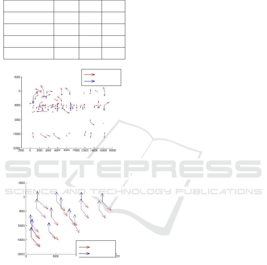
Table 6: Geo-location accuracy of the Dalian area by the
block adjustment parameter extrapolation (RMS/m).
Statistics Item X/m Y/m Z/m
Average error 13.433 32.787 25.668
Maximum residual
19.073 35.828 29.003
Minimum residual
8.173 28.771 22.223
RMS 13.683 32.860 25.742
Figure 5: Geo-location residual map of the Anping block
after adjustment.
Figure 6: Geo-location residual map of the Dalian area after
the use of the adjustment parameters of the Anping block
for extrapolation.
It can be seen from Tables 5 and 3 that, through the
self-calibrating block adjustment, the internal
orientation distortion is compensated, thereby further
escalating the geo-location accuracy of the Anping
area. This result also confirms the presence of internal
orientation distortion. In addition, from Tables 6 and
4, it is observed that, by applying the self-calibration
block adjustment parameters of the Anping area to the
extrapolative geo-location of the Dalian area, the geo-
location accuracy of the Dalian area is also enhanced,
although to a smaller extent. A comparison of Figs. 6
and 4 reveals a small change, indicating that there are
still systematic errors in the geo-location residual map
of the Dalian area. This result suggests that the block
adjustment parameters of the Anping area cannot
fully eliminate the systematic errors in the external
orientation attitude angle and installation matrix or
the internal orientation distortion in the Dalian area.
6 CONCLUSIONS
In this study, based on the strict geometric model of
the ZY-3 satellite, we propose the Rodrigues rotation
matrix to establish an attitude constant error
calibration model. In addition, by introducing an
additional parameter model considering the
aberration to compensate for the internal orientation
distortion, we constructed a block adjustment model
using the self-calibrating bundle method. This model
can derive the correction numbers of the internal and
external orientation elements using only a small
number of ground control points, thereby
substantially improving the imaging geo-location
accuracy. By introducing an additional parameter
model considering the aberration to compensate for
the internal orientation distortion, a block adjustment
model using the self-calibrating bundle method was
constructed. The model could derive the correction
numbers of both the internal and the external
orientation elements spontaneously, thereby
significantly enhancing the geo-location accuracy. In
addition, by applying the derived parameters to the
extrapolative geo-location of other areas, the geo-
location accuracy of these areas was also substantially
escalated. Finally, we analyzed why the accuracy of
the extrapolative geo-location areas could not reach
that of the original area. The methods and findings of
this study can serve as technical references for
accurate geo-location solutions of aerospace three-
line array imaging.
ACKNOWLEDGEMENTS
This paper was supported in part by National Key
Research and Development Project of China (Nos.
2016YFB0501005 and 2017YFB0504201), by the
National Natural Science Foundation of China (Nos.
41301525, 41571440 and 41771360), by the High
Resolution Remote Sensing, Surveying and Mapping
Application Program (No.2).
Horizontal
Elevation
Horizontal
Elevation
X/m
X/m
Y/m
Y/m
GISTAM 2020 - 6th International Conference on Geographical Information Systems Theory, Applications and Management
110

REFERENCES
Bo Jia, Ting Jiang, Gangwu Jiang, et al., 2012. The High
Precision Direct Georeferencing of SPOT-5 Remote-
Sensing Imagery Based on Bias Matrix Calibration, J
Geom Sci Technol 29(5), 368-372.
Chengzhi Sun, Xinming Tang, 2009. China's first civil
three-dimensional surveying and mapping satellite -
Resource No.3 and its application, Aerospace China
2(9), 3-5.
Chubin Liu, 2012. Study on Crucial Technique of the On-
orbit Geometric Calibration of High Resolution
Satellite, Zhengzhou: Information Engineering
University.
Chubin Liu, Yongsheng Zhang, Dazhao Fan, et al, 2014.
Self-calibration Block Adjustment for Three Line
Array Image of ZY-3, Acta Geod Cartogr Sin 43(10),
1046-1050.
Dazhao Fan, Chubin Liu, Rong Lei, et al, 2013. Detection
of Constant Angular Error for ZY03 Panchromatic
Imagery, Geomatics World 20(4), 37-40.
Deren Li, 2012. China's First Civilian Three-line-array
Stereo Mapping Satellite: ZY-3, Acta Geod Cartogr Sin
41(3), 317-322.
Jinshan Cao, Xiuxiao Yuan, Jianya Gong, et al., 2014. The
Look-angle Calibration Method for On-orbit Geometric
Calibration of ZY-3 Satellite Imaging Sensors, Acta
Geod Cartogr Sin 43(10), 1039-1045.
Rong Lei, 2011. Study on Theory and Algorithm of the In-
flight Geometric Calibration of Spaceborne Linear
Array Sensor, Zhengzhou: Information Engineering
University.
Tianhong Gan, Li Yan, 2007. The Study of Ridge-
estimation-based Decorrelation Method for Three Line
Scanner CCD Image’s Exterior Orientation Elements,
Bull Surv Map 11(3), 19-22.
Xiuxiao Yuan, Jinshan Cao, 2012. Theory and method of
precise ground target positioning for high-resolution
satellite remote sensing, Science Press, Beijing.
Xiuxiao Yuan, Junpeng Yu, 2008. Calibration of Constant
Angular Error for High Resolution Remotely Sensed
Imagery, Acta Geod Cartogr Sin 37(1), 36-41.
Yonghua Jiang, Guo Zhang, Xinming Tang, et al., 2013.
High Accuracy Geometric Calibration of ZY-3 Three-
line Image, Acta Geod Cartogr Sin 42(4), 523-529.
Zhiqiang Tang, Wenbo Su, Haijun Ge, 2010. The Inner
Orientation Modeling and Optimization of Space Line-
array CCD Sensor, Remot Sens Inf (6), 3-5.
Application of Rodrigues Matrix in High Accuracy Geo-location for ZY-3 Panchromatic Imagery
111
