
Linked Real and Virtual Test Environment for Distributed
C-ITS-Applications
Michael Kl
¨
oppel-Gersdorf
a
and Thomas Otto
Fraunhofer IVI, Fraunhofer Institute for Transportation and Infrastructure Systems, Dresden, Germany
Keywords:
V2X, Simulation, Hardware-in-the-Loop, Testing.
Abstract:
The development and test of automated and connected driving, based on vehicle-to-infrastructure (V2I) com-
munication, is essential for C-ITS pilot implementations. Even today, the deployment and test of these services
is a great challenge. Multiple connections, interfaces as well as interactions between several entities make it
difficult to find and eliminate malfunction of cooperative components. The ranges and boundaries of drive and
test scenarios make debugging during test drives in a real traffic environment substantially difficult, because it
requires reproducible conditions. The solution of the above mentioned problem is a linked real and virtual test
environment for distributed C-ITS-Applications under test. A microscopic simulation of traffic scenarios run-
ning on a test environment computer is combined with a real signal control device including traffic lights, real
roadside unit and a real on-board unit for the communication between infrastructure (traffic lights) and vehicle
(on-board unit). This hardware and software-in-the-loop (HiL/SiL) approach enables the use of reproducible
drive and test scenarios for testing C-ITS-Applications based on an interaction of different traffic conditions,
traffic light devices and vehicles.
1 INTRODUCTION
The development and deployment of Cooperative In-
telligent Transport Systems (C-ITS) applications for
urban traffic is a major challenge, where one active
topic is services for intersections with traffic lights.
It is well known that traffic lights impair the Level
of Service (LoS) in inner-city traffic flow as well as
the environment (Haberl et al., 2015). The impact
of traffic lights is also shown in (Otto and Hoyer,
2009). Many approaches, e.g., digitalization, commu-
nications, Vehicle-to-Everything (V2X) applications,
exist to minimize the impact of traffic lights. There-
fore, evaluating the effectiveness of the proposed so-
lutions is a crucial problem open for research.
In order to be able to analyze different approaches
and traffic scenarios, studies in real urban traffic flow
are necessary. Unfortunately, such studies are ex-
tremely time-consuming, expensive and may be in-
feasible due to safety concerns. One alternative to
these studies is the usage of linked real and virtual
test environments, where virtual components are cal-
ibrated and validated using real and possibly also live
measurement data. In this work, we propose a linked
a
https://orcid.org/0000-0001-9382-3062
real and virtual (i.e., simulated) test environment for
testing and evaluating implementations of C-ITS ser-
vices. The system is building on the real system ar-
chitecture for cooperative driving with heterogeneous
communications and cloud infrastructure described in
(Auerswald et al., 2019), which is implemented in
Dresden.
Hybrid tests of V2X communication scenarios are
no new development and have also been considered
in (Wang et al., 2019), where the authors concentrate
on testing the lower levels of the ITS communica-
tion stack. In addition, (Freese-Wagner, 2018) offers
a full testing kit for developing commercial applica-
tions, which might be too involved in a pure research
context. The authors of (Menarini et al., 2019) pro-
vide a Hardware-in-the-Loop (HiL) testing environ-
ment, which is focused on Vehicle-to-Vehicle (V2V)
applications. Their solution is based on a intermedi-
ate layer between V2X modem and the onboard com-
puter. This layer can be used to rewrite message con-
tents, i.e., the real position of the modem is overwrit-
ten with a position gained from traffic simulation, and
simulate message loss. Potential downsides of this
approach are the increased message latency and the
possibility to introduce further sources of errors in the
intermediate layer. In contrast, our approach uses a
Klöppel-Gersdorf, M. and Otto, T.
Linked Real and Virtual Test Environment for Distributed C-ITS-Applications.
DOI: 10.5220/0009426003770384
In Proceedings of the 6th International Conference on Vehicle Technology and Intelligent Transport Systems (VEHITS 2020), pages 377-384
ISBN: 978-989-758-419-0
Copyright
c
2020 by SCITEPRESS – Science and Technology Publications, Lda. All rights reserved
377

standard V2X stack with messages received as sent,
bringing our simulation closer to reality.
This paper is organized as follows: The next sec-
tion introduces the use cases we want to support with
our solution, whereas the following section describes
the different components, which need to be consid-
ered when implementing the test environment, as well
as our proposed solution. In Section 4 we evaluate
the suitability of our proposed solution. In the sec-
tion following afterward, different test scenarios for
Green-Light Optimized Speed Advisory (GLOSA)
and Probe Vehicle Data (PVD) are discussed. We con-
clude this work in the last section.
2 C-ITS SERVICES AND THE
C-ROADS GERMANY URBAN
NODES PILOT IN DRESDEN
Within the framework of C-ROADS Germany and C-
ROADS Germany - Urban Nodes, so-called Day-1
and Day-1.5 C-ITS application cases are being tested
in various German pilot locations, with one location
being the city of Dresden. Dresden provides a V2X
test corridor, which runs along on heavily loaded city
roads, including main roads and access roads. The
traffic lights in the corridors will be gradually up-
graded for Vehicle-to-Infrastructure (V2I) communi-
cation. The project is coordinated by Fraunhofer In-
stitute for Transportation and Infrastructure Systems
IVI.
The pilot focuses on the deployment of Day 1
and Day 1.5 services. These C-ITS pilot-services are
based on the following C-ITS applications:
• GLOSA
• PVD
• Traffic Signal Priority request (TSP)
• Emergency Vehicle Approaching (EVA)
• Vulnerable Road Users (VRUs)
The first services, that will be implemented in the
Dresden pilot are GLOSA and PVD.
2.1 GLOSA
Intersections cause delay and stops thereby negatively
affecting environmental pollution and traffic safety.
At signalized intersections actual and/or predicted in-
formation on the phases and timing of traffic lights
can be given to road users to optimize their driving
and to overcome the inefficiencies. An application
can calculate a speed advice for one or multiple in-
tersections, which enables approaching road users to
adapt their speed and to pass one or more signal-
controlled intersections in an energy efficient manner
(e.g., by minimizing stops, acceleration and decelera-
tion), safely and sustainably.
The objectives are:
• Decrease of number of stops, travel times and
waiting times,
• Increase of LoS of traffic flow and road network
quality,
• Increase of safety on signalized intersections.
2.2 PVD
PVD is a Day-1 application. Acquisition of road traf-
fic data is an important aspect of traffic management
systems. An innovative approach is utilizing the ve-
hicles themselves as a source of real-time traffic data,
functioning as roving traffic probes. The PVD service
gathers anonymized sensor data (e.g. speed, braking
force and weather conditions) from passing vehicles
using secure ETSI ITS G5 connections. The objec-
tives are:
• Traffic and congestion monitoring,
• Input data and information for traffic manage-
ment,
• Increase of LoS of traffic flow and road network
quality,
• Decrease of travel times and waiting times.
3 IMPLEMENTATION
The basic solution of the linked real and virtual test
environment for distributed C-ITS-Applications com-
prises of the following components:
1. Microscopic simulation of traffic scenarios using
the SUMO tool running on a test environment
computer (simulation computer),
2. Real signal control device including traffic lights,
3. Own implementation of the ETSI ITS-G5 facili-
ties,
4. Real roadside unit for the communication be-
tween infrastructure (traffic lights) and vehicle
(on-board unit),
5. Real on-board unit for the communication be-
tween infrastructure (traffic lights) and vehicle
(on-board unit),
6. Backend for roadside units,
7. Mobile cloud,
VEHITS 2020 - 6th International Conference on Vehicle Technology and Intelligent Transport Systems
378

8. Display of center console in vehicle or tablets as
Human-Machine-Interface (HMI) to visualize C-
ITS applications.
Figure 1 shows how these different components
are connected.
3.1 Microscopic Simulation
Depending on the use case, it may often be desirable
to simulate (additional) traffic and/or traffic lights.
Here, we use Simulation of Urban Mobility (SUMO)
(Krajzewicz et al., 2012) for microscopic traffic sim-
ulation. The network topology is usually created
from OpenStreetMap (OSM) with additional post-
processing to clean up artifacts. Traffic demand can
be obtained from historic or real time data. For more
details on the SUMO simulation see (Kloeppel et al.,
2019). The simulation is accessed using Traffic Con-
trol Interface (TraCI) using the multiclient capabil-
ity introduced in the newer versions of SUMO. As
SUMO usually performs simulation steps as fast as
possible, one of the external clients is used to handle
the timing in the case a real time operation is desired.
Since this works only in the case that SUMO calcu-
lates faster than real time, it is necessary to assure that
this can be done at any simulation step, e.g., by using
a more powerful simulation machine or using the par-
allel simulation feature.
3.2 Signal Control Device
At the moment, signal control devices of different
suppliers are equipped with Road-Side Units (RSUs).
Some signal control devices provide a socket connec-
tion, which delivers a status message containing cur-
rent signal state, traffic signal priority requests, detec-
tor status and predictions (in the case of a fixed plan)
every second. The content is in Protobuf (Google,
2018b) format and can be ingested by the RSU. Other
signal control devices at least provide signal state in-
formation and possibly also predictions if the required
module is installed. Additional information might be
available via the traffic management system.
3.3 Implementation of ETSI ITS-G5
Facilities
We use our own implementation of the ETSI ITS-
G5 facilities called Communications for Connected
and Automated Road Traffic (C4CART). This al-
lows us to implement and experiment with message
types, which are not (yet) fully standardized as well
as using completely standardized messages. Figure 2
shows the ITS communication stack with the message
types supported by C4CART highlighted. Besides
the standardized message types Cooperative Aware-
ness Message (CAM), Decentralized Environmental
Notification Message (DENM), Map Extended Mes-
sage (MAPEM), and Signal, Phase and Timing Ex-
tended Message (SPATEM), C4CART also supports
Collective Perception Message (CPM) (for exchang-
ing sensor information) and Maneuver Coordination
Message (MCM), Maneuver Recommendation Mes-
sage (MRM) (for maneuver coordination). The com-
munication between the application layer and the fa-
cilities layer is carried out using Lightweight Com-
munications and Marshalling (LCM) (Huang et al.,
2010), which is based on an UDP multicast. Our so-
lution exploits this multicast to inject messages to the
application layer, which are indistinguishable from
messages received via V2X communication.
3.4 RSUs
As of now, more than twenty RSUs are installed in
the Dresden Testbed, both for productive and scien-
tific use. The productive RSU are provided by suppli-
ers of traffic lights, whereas the ones for scientific use
are custom build using a V2X modem (mostly MK5s
from Cohda Wireless), a LTE router and one or more
computation units (e.g., HummingBoard Edge from
SolidRun or Jetson TX2/AGX from NVIDIA). While
the HummingBoards can be used for basic process-
ing, the Jetsons allow some more involved edge pro-
cessing, e.g., sensor fusion. Usually, C4CART is used
on the V2X modem, whereas the application run on
either the HummingBoard or the Jetson. The appli-
cations themselves are organized as microservices us-
ing gRPC Remote Procedure Calls (gRPC) (Google,
2018a) with ProtoBuf for communication. Certain ap-
plications also maintain a connection to our central
backend using a Message Queuing Telemetry Trans-
port (MQTT) connection. This allows to provide sim-
ulations and test runs with current traffic data like sig-
nal state and detector inputs. A more detailed descrip-
tion of the RSU can be found in (Strobl et al., 2019;
Auerswald et al., 2019).
3.5 On-Board Units (OBUs)
As OBUs solutions from Cohda Wireless (MK5) and
Preh Car Connect (Connectivity Box (C-BOX)) are
used. Both solutions are quite similar, except that
the C-BOX delivers additional WiFi and Long Term
Evolution (LTE) connection abilities. Even applica-
tions can be shared between the two systems with-
out the need for recompilation. The OBUs usually
run C4CART, the backend of our HMI as well as any
Linked Real and Virtual Test Environment for Distributed C-ITS-Applications
379
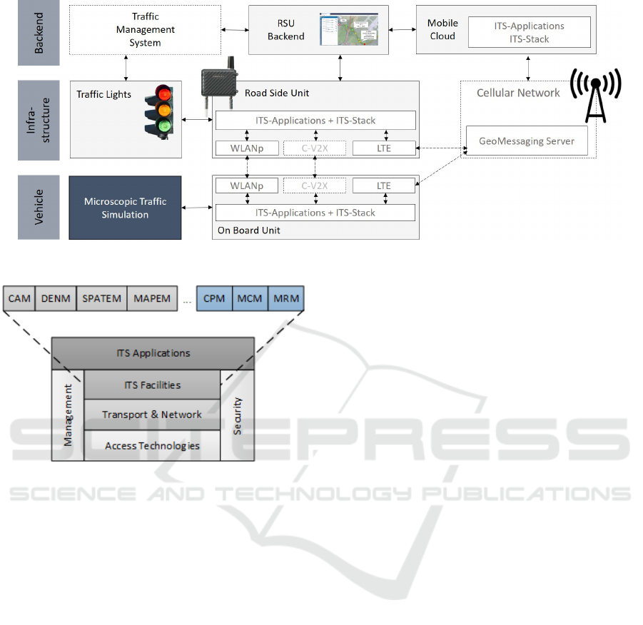
Figure 1: Different components of our proposed solution and their connections.
Figure 2: ITS communication stack. C4CART is used to
provide the ITS facilities. Figure reproduced from (Auer-
swald et al., 2019).
components required by our testing framework. If
necessary, they can also connect to the central back-
end.
3.6 Backend
The backend consists of several different services,
e.g., a database for topology data, data storage for
logging purposes, visualization capabilities showing
the current state of the Dresden Testbed and a MQTT
message broker relaying messages between the var-
ious participants. Additionally, the backend ingests
additional data for the traffic lights from Dresden’s
traffic management system and makes it available to
the single RSUs to enhance the SPATEM with prog-
nosis information allowing to implement the GLOSA
service.
3.7 Mobile Cloud
Our ITS-G5 facilities implementation follows a hy-
brid approach, allowing messages not only be send
via 802.11p or Cellular V2X (C-V2X) but also via
a LTE connection (for more details see (Auerswald
et al., 2019)). This allows for test cases, where direct
V2X communication is currently not available
3.8 HMI
In order to visualize V2X communication, we devel-
oped a HMI as can be seen in the lower part of Fig-
ure 4. Besides visualizing phase and GLOSA infor-
mation it is also able to communicate maneuver rec-
ommendations received via the research message for-
mats MCM and MRM. It also aids tests drivers in
real world test scenarios with driving recommenda-
tions (Otto and Auerswald, 2020). The HMI consists
of two parts. The visualization runs on Android de-
vices, whereas backend services like message decryp-
tion run on the OBU.
3.9 Solution Architecture
The proposed solution is based on an existing module,
which allows to import the current signal status and
detector inputs of the traffic signals on the Dresden
Testbed into a SUMO simulation. The module ex-
ploits the fact that every RSU in the Dresden Testbed
reports the current signal state to the backend. For
this purpose, the backend operates a highly available
MQTT broker (EMQ X broker (EMQ Technologies
Co., Ltd., 2019)). A custom message format based on
Protobuf is used. For the desired use case the existing
solution is extended to not only import information
into the SUMO, but to also export information (e.g.,
vehicle data in the forms of generated CAMs). This
information is then transmitted via MQTT and can be
received by other modules. These modules can then
inject data to the V2X applications using the multicast
VEHITS 2020 - 6th International Conference on Vehicle Technology and Intelligent Transport Systems
380
OBU
Simulated
CAM
import
C4CART
HMI
backend
RSU
Simulated
CAM
import
C4CART
RSU
app-
lications
LCM
LCM
802.11p
LTE-V2X
LTE
LCM
LCM
MQTT broker (local or remote)
Simulation computer
SUMO
simulation
Simulated
CAM
generation
TraCI
LCM over MQTT
LCM over MQTT
Figure 3: Architecture of our proposed solution. Signal
control device and HMI are left out in this schematic, but
would be connected to the RSU and OBU, respectively. One
special feature of the CAM import on the OBU side is the
ability to treat certain CAMs as source for the ego vehicle
position.
feature of LCM described above. For any application
this data is indistinguishable from data received di-
rectly from the ITS facilities. Figure 3 shows an ex-
ample setup as used in the evaluation section below.
We also propose to operate local MQTT message
brokers based on Mosquitto (Light, 2017), which the
single modules can connect to. Usage of a local or re-
mote MQTT server can be handled solely by config-
uring Mosquitto without need to reconfigure the sin-
gle modules. Also of importance is the right choice of
MQTT Quality of Service (QoS). We opt for level two
(every message is received only once) even though
this may lead to higher latencies, as any lower QoS
might lead to message loss or multiple versions of the
same message being received.
4 EVALUATION AND
VERIFICATION
In most cases, C-ITS applications are designed for
real-time capability. This applies in particular to ap-
Figure 4: Visual confirmation of the correct phase informa-
tion being send by the RSU. The signal corresponding to
the left turn is not visible in this picture. Also note that the
movement of the vehicle is simulated, the vehicle itself is
only used for its V2X and visualization capabilities.
plications that are deployed in connection with traf-
fic light data and information (GLOSA) as well as
other intersecting roads (PVD and other services). In
the aforementioned case, even small latency in com-
munication leads to problems regarding the security
of the information provided. Latency afflicted infor-
mation causes delayed or incorrect data. Therefore,
the investigation of latencies in the deployed systems
is essential. For evaluation, we measure the mes-
sage latency (between the generation in the simula-
tion and receiving in the consuming applications, or
more clearly between the grey boxes in Figure 3) for
a reference scenario simulating the approach of three
connected vehicles towards an intersection equipped
with a RSU (intersection 805 (to the east of the high-
way A4) on the Dresden airport corridor, see (Strobl
et al., 2019)). Here, we use a real signal control de-
vice with an attached RSU as well as a real OBU with
attached visualization. Goal of this test is to verify
the correct transmission of SPATEM, especially with
respect to changes in the signal schedule due to the
detectors of the signal control device being triggered
by the simulated vehicles. Figure 4 shows the exam-
ple of a visual confirmation that the right information
was sent. Please note that the actual evaluation will be
done based on logs of signal device state, RSU send-
ing log files, OBU receiving log files, and possibly
Linked Real and Virtual Test Environment for Distributed C-ITS-Applications
381
5
1 7
5 5
2 7 7
2 3 4 7
1 3 0 4 2
2 1 8 4
2 2 9
4 0
9
0 . 0 4 0 . 0 6 0 . 0 8 0 . 1 0 0 . 1 2 0 . 1 4 0 . 1 6
0
2 0 0 0
4 0 0 0
6 0 0 0
8 0 0 0
1 0 0 0 0
1 2 0 0 0
1 4 0 0 0
O c c u r e n c e c o u n t o f c o m p u t a t i o n s t e p t i m e
C o m p u t a t i o n s t e p t i m e [ s ]
Figure 5: Computation times for a single computation step.
even more data.
We consider two different scenarios. The first re-
lies only on local communication, whereas the second
uses a message broker located in our backend, which
is accessed via a cable-based connection. As men-
tioned above, the only difference between these two is
the configuration of the MQTT message brokers, ev-
erything else, including application configuration, is
the same. As we want to test the signal control device
plus the attached RSU, tests have to run in real time in
order to avoid synchronizing issues with the internal 1
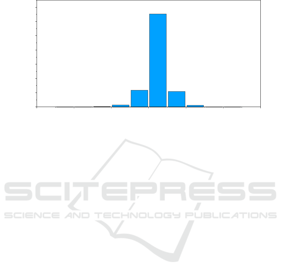
Hz frequency of the signal control device. We choose
to run our simulation with a frequency of 10 Hz (cor-
responding roughly to a movement of two meters be-
tween two simulation steps at the maximum allowed
velocity). This ensures that the detectors are actually
triggered at an appropriate time. Figure 5 shows that
we can ensure a step time of 0.1 s corresponding to
the 10 Hz frequency.
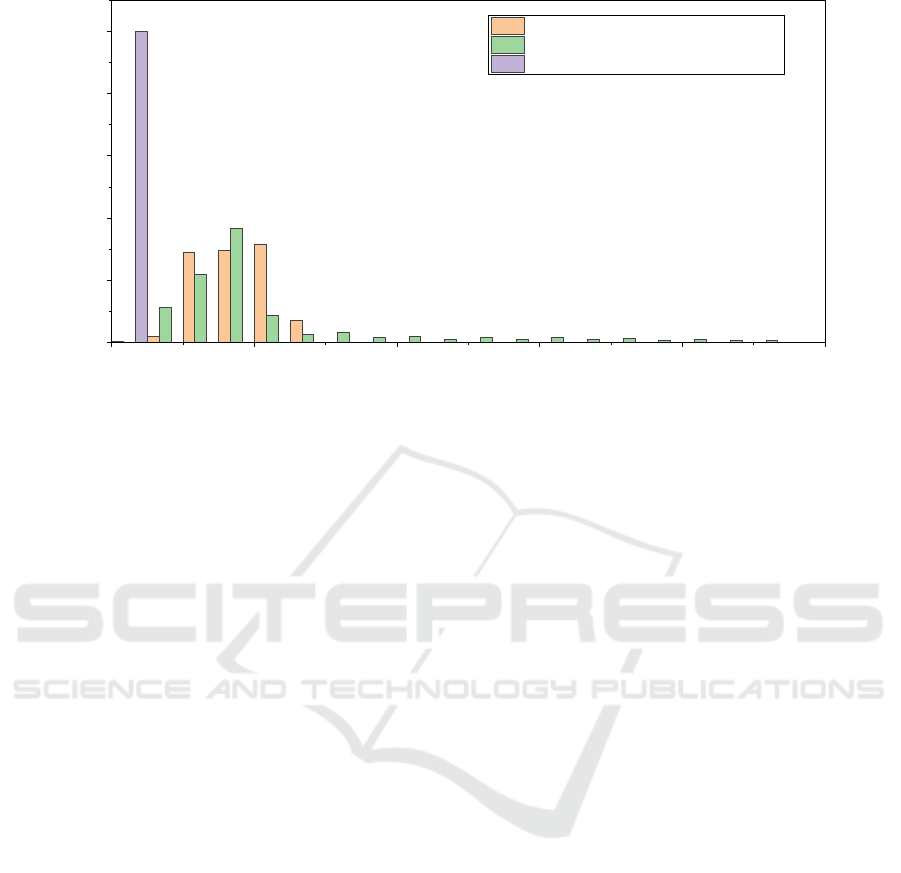
The measurement results for the local case are
shown in Figure 6. A total of over 50,000 messages
are considered. No message is lost, whereas the me-
dian latency is 0.7 ms, which is less than the median
message latency of 9.44 ms measured in (Strobl et al.,
2019) for an over the air transmission (also shown in
Figure 6).
The results for the backend connection are quite
different, with significatly higher latencies, which is
to be expected due to the usage of a remote message
broker. About 10 % of the messages require more
than 25 ms, with a worst case latency of about 200
ms. These can be explained by network congestion
and the use of QoS level two for the MQTT connec-
tion. Nevertheless, the occurence of such latencies
should be kept in mind when testing latency critical
application, e.g., GLOSA.
5 USE CASES
In this section, we will show how the proposed so-
lution can used to test the two services GLOSA and
PVD mentioned in the introduction.
5.1 GLOSA
The first use case is quite similar to the test case pre-
sented in Section 4. Using a real signal control de-
vice, RSU and OBU verify that the correct signal
state is transmitted via V2X. Once correctness can
be assured, the next step is to examine if the right
remaining time is send. In order to do this one can
rely on historical data available in the backend. As
a final step, the correct transmission of the GLOSA
advice inside can be tested. This comprises the cor-
rect transmission of the GLOSA recommendation as
well as the soundness of the advice. Be advised that
the proposed solution helps to determine errors on
the RSU/signal control device side as well as on the
OBU/HMI side as log files being written at several
steps in the process allow the identification of mal-
functioning parts. Even another use case is the con-
duction of acceptance tests, which can carried out
without the need to drive in real traffic. Especially
in the first steps of developing V2X solutions, this
can enable rapid feedback and development as diffi-
cult drives and possibly insecure (e.g., drivers react-
ing on a wrong GLOSA recommendation) situations
VEHITS 2020 - 6th International Conference on Vehicle Technology and Intelligent Transport Systems
382
0 1 0 2 0 3 0 4 0 5 0
0 . 0
0 . 2
0 . 4
0 . 6
0 . 8
1 . 0
R e l a t i v e f r e q u e n c y o f m e s s a g e l a t e n c y o c c u r e n c e
M e s s a g e l a t e n c y [ m s ]
R e a l w o r l d r e f e r e n c e m e a s u r e m e n t s
R e m o t e M Q T T
L o c a l M Q T T
Figure 6: Measured message latencies for the local and remote MQTT connection. Median latency is 1 ms for the local
MQTT and 8ms for the remote connection. The maximum latencies are 8 ms and 190 ms, respectively. For comparison, the
results of real world over-the-air transmission measured in (Strobl et al., 2019) are also given.
can be avoided.
5.2 PVD
As described above, CAMs can be generated for every
vehicle inside the SUMO simulation. These CAMs
can be used to provide PVD. Therefore, a first test ob-
jective would be to ascertain that data obtained from
the simulation actually coincides with the situation in-
side the simulation.
6 CONCLUSIONS AND
OUTLOOK
Our measurements have shown that our system is
able to reliably exchange messages, thereby allowing
to enhance real testing with simulated information.
While no message was lost in the test case, message
latency could be improved further by providing better
networking. Nonetheless, the proposed solution al-
lows a multitude of testing scenarios, i.e., the linked
real and virtual test environment for distributed C-ITS
applications proposed above will be used to develop,
test and deploy further services like TSP, EVA and
VRU.
TSP is a Day-1 application. Traffic signal prior-
ity aims at changing the traffic signals status in the
path of an emergency or of a high priority vehicle
(e.g. public transportation vehicle), halting conflict-
ing traffic and allowing the vehicle right-of-way, to
help reduce response times and enhance traffic safety.
Different levels of priority may be applied depending
on vehicle characteristics, such as type (e.g., emer-
gency vehicles) or status (e.g. public transport vehi-
cle on-time or behind schedule). The vehicles request
priority for an intersection, and the traffic light con-
troller determines how it can (and will) respond to the
request.
EVA is a Day-1 application. As the name implies,
an emergency vehicle is operated under conditions
and circumstances of danger to life or property. The
regular rules of the road, traffic signs and signals that
apply to other traffic are suspended while such vehi-
cle is approaching with sounding siren and flashing
lights. While such rules may be waived to provide a
swift response to an emergency, the law does impose
an obligation on all drivers of emergency vehicles to
exercise due care for the safety of other persons. They
are still responsible for the safe operation of their ve-
hicle.
VRU (also known as ”Vulnerable road user Warn-
ing”) is a Day-1.5 application. VRUs are defined in
the ITS directive as ”non-motorized road users, such
as pedestrians and cyclists as well as motor-cyclists
and persons with disabilities or reduced mobility and
orientation”. A warning system for VRUs aims at the
detection of risky situations, allowing the possibility
to warn vehicle drivers. The scope of the pilot ser-
vice will be on cyclists as VRUs. The pilot service is
particularly valuable when the driver is distracted or
visibility is poor.
The advantages of HiL testing for distributed C-
ITS applications are undeniable, since it allows the
Linked Real and Virtual Test Environment for Distributed C-ITS-Applications
383

development in and debugging of complex drive and
test scenarios. Furthermore, it allows the test of a
multitude of interfaces, connections and devices un-
der natural conditions, all of which can be done under
reproducible drive and test scenarios. On top, it can
also be used to perform stress tests with real devices
and interfaces by, e.g., variation of different penetra-
tion rates.
ACKNOWLEDGEMENTS
This research is financially supported by the German
Federal Ministry of Transport and Digital Infrastruc-
ture (BMVI) under grant numbers FKZ 16AVF1024
(HarmonizeDD), European Regional Development
Fund (ERDF) and European Union “Connection Eu-
rope Facility” (C-Roads Urban Nodes). We would
like to thank Stephan Ihrke for implementing parts of
the solution.
REFERENCES
Auerswald, R., Busse, R., Dod, M., Fritzsche, R., Jung-
mann, A., Kl
¨
oppel-Gersdorf, M., Krems, J. F., Lorenz,
S., Schmalfuß, F., Springer, S., and Strobl, S. (2019).
Cooperative driving in mixed traffic with heteroge-
neous communications and cloud infrastructure. In
Proceedings of the 5th International Conference on
Vehicle Technology and Intelligent Transport Sys-
tems - Volume 1: VEHITS,, pages 95–105. INSTICC,
SciTePress.
EMQ Technologies Co., Ltd. (2019). EMQ X broker project
page. https://www.emqx.io. Accessed: 2019-12-18.
Freese-Wagner, M., editor (2018). A Rapid Innovation
Framework for Connected Mobility Applications :
High Performance Center Connected Secure Systems.
Fraunhofer AISEC, EMFT & ESK. Fraunhofer ESK,
M
¨
unchen.
Google (2018a). gRPC project page. https://grpc.io. Ac-
cessed: 2018-01-23.
Google (2018b). Protocol buffers project page.
https://github.com/google/protobuf. Accessed:
2018-01-23.
Haberl, M., Cik, M., Fellendorf, M., Otto, T., Luz, R., and
Roth, P. (2015). Emission minimizing adaptive signal
control: A multimodal optimization approach. In Pro-
ceedings of the 22nd ITS World Congress, Bordeaux,
France.
Huang, A. S., Olson, E., and Moore, D. C. (2010). LCM:
Lightweight communications and marshalling. In
2010 IEEE/RSJ International Conference on Intelli-
gent Robots and Systems, pages 4057–4062.
Kloeppel, M., Grimm, J., Strobl, S., and Auerswald,
R. (2019). Performance evaluation of GLOSA-
algorithms under realistic traffic conditions using C2I-
communication. In Nathanail, E. G. and Karakikes,
I. D., editors, Data Analytics: Paving the Way to Sus-
tainable Urban Mobility. CSUM 2018, volume 879
of Advances in Intelligent Systems and Computing,
pages 44–52, Cham. Springer International Publish-
ing.
Krajzewicz, D., Erdmann, J., Behrisch, M., and Bieker,
L. (2012). Recent development and applications of
SUMO - Simulation of Urban MObility. International
Journal On Advances in Systems and Measurements,
5(3&4):128–138.
Light, R. A. (2017). Mosquitto: server and client implemen-
tation of the mqtt protocol. Journal of Open Source
Software, 2(13):1.
Menarini, M., Marrancone, P., Cecchini, G., Bazzi, A.,
Masini, B. M., and Zanella, A. (2019). Trudi: Testing
environment for vehicular applications running with
devices in the loop. In 2019 IEEE International Con-
ference on Connected Vehicles and Expo (ICCVE),
pages 1–6.
Otto, T. and Auerswald, R. (2020). Toolbox for test plan-
ning and test realization of scenario-based field tests
for automated and connected driving. In Bertram, T.,
editor, Automatisiertes Fahren 2019, pages 165–180,
Wiesbaden. Springer Fachmedien Wiesbaden.
Otto, T. and Hoyer, R. (2009). Devices-in-the-loop ap-
proach - traffic simulation meets real devices of dis-
tributed v2i applications. In mobil.TUM 2009 – Inter-
national Scientific Conference on Mobility and Trans-
port. Proceedings.
Strobl, S., Kl
¨
oppel-Gersdorf, M., Otto, T., and Grimm, J.
(2019). C-its pilot in dresden – designing a modu-
lar c-its architecture. In 2019 6th International Con-
ference on Models and Technologies for Intelligent
Transportation Systems (MT-ITS), pages 1–8.
Wang, J., Shao, Y., Ge, Y., and Yu, R. (2019). A survey of
vehicle to everything (v2x) testing. Journal of Open
Source Software, 19(334).
VEHITS 2020 - 6th International Conference on Vehicle Technology and Intelligent Transport Systems
384
