
From BPMN to Sequence Diagrams: Transformation and Traceability
Aljia Bouzidi
1
, Nahla Zaaboub Haddar
1
, Mounira Ben-Abdallah
1
and Kais Haddar
2
1
Faculty of Economics and Management, Sfax University, Sfax, Tunisia
2
Faculty of Sciences, Sfax University, Sfax, Tunisia
Keywords:
Alignment, Traceability, Model Transformation, BPMN Model, UML Sequence Diagram, MVC.
Abstract:
A business cannot be competitive unless its business process is aligned with its information system. Indeed, a
perfect alignment is key to a coherent management and success of the business. Therefore, it is important to
bring closer business process- and IS modeling activities. The current paper presents an approach to derive a
dynamic software model from a business process model, including the trace links between source and target
elements. Our approach is based on a set of rules that transform a BPMN business process model into a UML
sequence diagram structured according to the model view controller design pattern, and a trace model. To
show the feasibility of approach in the practice, we developed a tool that implements the transformation rules.
1 INTRODUCTION
A business process model (bpm) represents the way
operations are carried out to accomplish business
goals. An automated information system (IS) gives
important support to the bpm if its capacities are
best exploited. Indeed, the IS can offer complete in-
formation, allowing to manage one’s business more
efficiently, gain a cost advantage over competitors,
and make tough decisions. However this can not be
reached when the business process is not aligned with
its IS. Therefore, it is important to start IS modeling
from bpm. In modern software development meth-
ods, analysts start the development process with an
inception phase to acquire a deep knowledge of the
business process model. This phase is crucial since
it prepares for requirement discovery and analysis.
However, artifacts produced in this phase, such as
the bpm, are not exploited in downstream software
development phases. A transformation mechanism
would produce models that can be used as a staring
point for the construction of the structural and be-
havioural perspectives of the analysis model. The
Model Driven Architecture approach (MDA) (OMG-
MDA, 2006) recommends the model transformation
mechanism between heterogeneous models. Accord-
ingly, the transition from the problem domain ex-
pressed with BPMN notations into software models
expressed with UML may be resolved basing on the
principles of model transformation from the compu-
tation independent model (CIM) level that hosts the
business model into the platform-independent model
(PIM) level that encloses the IS analysis models. The
MDA approach is commonly used to get from a PIM-
to a platform-specific model (PSM) then from a PSM
to code. But, very little works have contributed to the
CIM to PIM transformation, which in turn commonly
focus on the static or/and functional viewpoints.
On the other hand, if a change of the IS model
is needed, great efforts, money and time are wasted
during the modification process to accommodate the
impact of changes, as there is a request to check con-
tinuously if the business process model is aware of
the changes. Therefore, the need for an approach that
deals with the changes of models is of great value to
software engineers (Arman and Jabbarin, 2015), (Jab-
barin and Arman, 2014). Traceability is an attempt
to address this issue. It consists in establishing trace
links between overlapping elements. These links may
be used then for various practical software diagrams,
such as model consistency check, change impact anal-
ysis and identification of misalignment sources. How-
ever, traceability is not enough addressed in the liter-
ature.
These shortcomings form the main motivation fac-
tor to propose a new approach that defines model
transformations for generating the sequence dia-
grams from a bpm expressed in BPMN (OMGBPMN,
2013). Besides, it defines a set of trace links that allow
relating the overlapping elements to maintain them al-
ways aligned. This work is complementary to existing
works that deal with static and functional viewpoints
438
Bouzidi, A., Haddar, N., Ben-Abdallah, M. and Haddar, K.
From BPMN to Sequence Diagrams: Transformation and Traceability.
DOI: 10.5220/0009418104380445
In Proceedings of the 15th International Conference on Evaluation of Novel Approaches to Software Engineering (ENASE 2020), pages 438-445
ISBN: 978-989-758-421-3
Copyright
c
2020 by SCITEPRESS – Science and Technology Publications, Lda. All rights reserved

of the analysis model of the IS so that it can be reused
and refined during the overall system design process
(Berrocal et al., 2014).
To get to the heart of our approach, the remain-
der of this paper is structured as follows. The next
section 2 discusses related works. In the third sec-
tion 3, we provide the current proposal contributions.
The fourth section 4 denotes the main advantages of
our approach. Finally, section 5 concludes and draws
some future works.
2 RELATED WORK
We classify related work into three categories accord-
ing to the method used to obtain the target models: (1)
natural language, (2) MDA, and (3) algorithm.
The first category of works includes (Yue et al.,
2010) and (Maciaszek and Filipe, 2015) which use
the informal description of use cases to generate
sds. The approach in (Alami et al., 2017) ad-
dresses the problem of generating sds from user
requirements expressed in Arabic. It is a semi-
automated approach that use a natural language pro-
cessing tool (NLPT).The aforementioned approaches
focused only on the user requirements, which do not
guarantee that the system supports the business activ-
ities. Further, requirement specifications expressed in
natural language may contain semantic ambiguities or
implicit information, which may lead to different in-
terpretations and consequently to inappropriate sds.
(Khan and Mahmood, 2016) falls into the sec-
ond category (MDA) of related works. It proposes
to transform a use case map into a sd. Further,
(De Souza and de Castro Giorno, 2015) defined a set
of rules for marking-up use cases, and developed a
transformation process that works according to these
rules to generate sds. Moreover, (Kang et al., 2010)
propose to transform viewpoints of human type in a
scenario into objects to actor messages, while view-
points of non-human type are transformed into object
to object messages.These works addresses only soft-
ware models (use case and sd), while the bpms are out
of their scope. A recent approach (Nikiforova et al.,
2016) propose a transformation method that gener-
ates the sd from a new model called two-hemisphere
model. But, the new model is not enough rich to
represent a complete bpm. Another recent work is
proposed by (Khlif et al., 2018). It uses an anno-
tated BPMN model as a starting point to generate a
sd. However, some important BPMN elements, such
as exception events, signal events, looping activities,
etc., were not addressed in this work. Although it may
resolve the misalignment problem, the use of a non-
standard model may reduce the usability of the ap-
proach as it requires specific but non-standard editors
to design these models. Further, the use of annota-
tions expressed informally may generate inconsistent
sds.
The third category of related works (algorithm) in-
cludes (Suchenia et al., 2017) which defined an al-
gorithm to transform a BPMN model into a sd that
may be used by business analysts and software en-
gineers to resolve time issues. In addition, (Salami
and Ahmed, 2014) and (Nassar et al., 2017) propose a
semi-automated algorithm to generate sds from state-
ments of event flows contained within the use case
models. Moreover, (Canal et al., 2018) propose an
algorithm that supports the integration of sds by mea-
suring the difference between two sequence messages
exchanged by objects. Even if defining an algorithm
helps to obtain an accurate result, a formal transfor-
mation language may enhance this approach.
Despite the various approaches dealing with sd
modeling, there are no previous works which address
the traceability between source and target models.
Moreover, there is no approach proposed to structure
the resulting sd according to the MVC pattern. To
our knowledge, there are no approaches which gener-
ate sds directly from BPMN standard (OMGBPMN,
2013) or without using other UML diagrams. More-
over, only (Khlif et al., 2018) deal with semantics of
source models.
3 BUSINESS PROCESS to-Trace
THE SEQUENCE DIAGRAM
We propose a semi-automatic MDA compliant-
approach called Business Process to-Trace UML
Sequence Diagram (BPto-TraceUSD) that aims to
create a dynamic view of software models that sup-
ports business expectations, and keeps them always
aligned even if they evolve. It defines an automatic
model transformation from the CIM to the PIM levels
by considering the syntax and the semantic perspec-
tives of the source and the target models. The source
model at the CIM level is the bpm expressed with
BPMN 2.0. The target model at the PIM is a set of sds
structured according to the MVC design pattern. We
use the standard notation BPMN 2.0 and UML 2.5.1
without any adaptation. Thus, we assume that the
reader is familiar with them. To maintain the align-
ment of the source and target models, and to guarantee
that the IS model meets always the business require-
ments, we define trace links between source- and tar-
get elements throughout the transformation process.
Figure 1 outlines our approach.
From BPMN to Sequence Diagrams: Transformation and Traceability
439
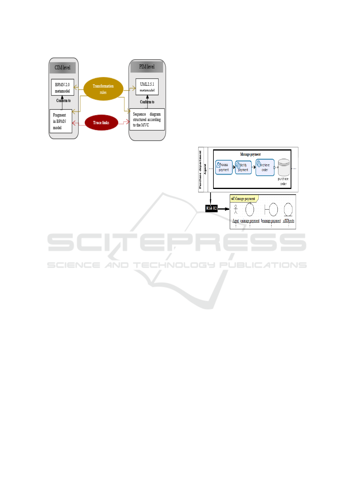
Figure 1: Overview of the our approach.
3.1 Transformation of Fragments
In (Bouzidi et al., 2017), we proved that a use case
is generated from a canonical fragment F obtained
by the decomposition of the BPMN model into frag-
ments. Therefore, the proposed BPMN-to-sequence
diagram transformation rules operate on each element
of a canonical fragment F. Transformation rule R1 is
defined as follow;
R1. For each canonical fragment F in BPMN:
1. Create an interaction (frame) of sd that has the
name of F.
2. Create a boundary and a control lifelines, which
have the same name as F preceded respectively
by b and c.
3. Create a collection of objects called allObjects as
a lifeline that represents all persistent objects that
participate in the execution of the fragment F.
4. Traceability: Create a trace link stereotyped Trace
from the interaction, the control and the boundary
lifelines, and allObjects to F.
3.2 Transformation of Empty Lanes
With empty lanes/pools, we mean those lanes/pools
that do not incorporate child lane sets. They are com-
monly used to represent internal roles of organiza-
tional units (e.g. Manager, Associate), and systems
(e.g. enterprise application). An empty lane/pool
is semantically equivalent to the actor definition in
UML.
R2. For each empty lane/pool EMP-L that incor-
porates a fragment F:
1. Create an object Obj in the interaction I represent-
ing F(created by R1). The type of obj is Actor and
its role is set to the name of EMP-L.
2. Traceability: Create a link stereotyped Trace from
obj to EMP-L.
Figure 2 depicts an example of applying R1 and R2
to an extract of a business model that contains a
fragment called Manage payment performed in an
empty Lane called Agent. By applying R1 on this
fragment, a sd interaction called Manage payment is
generated. In this interaction, R1 creates a control
and a boundary lifelines called respectively cManage-
Payment bManagePayment, and an object collection
called allObjects that represents all persistent objects
having an impact on the execution of this fragment.
Moreover, R2 is applied on the empty Lane Agent to
generate an actor called Agent in the sd interaction.
Figure 2: Example of R1 and R2 application.
3.3 Transformation of Item Aware
Elements
Item Aware Elements (IAEs), which are data objects,
data stores, data inputs, and data outputs, are required
(read) or produced (written) by BPMN tasks to fulfill
their business objectives. From a software develop-
ment viewpoint, many contributions such as(Brdjanin
et al., 2019), (Cruz et al., 2015b) and (Cruz et al.,
2015a) confirm that IAEs are semantically close do-
main classes in UML.
R3. For each IAE that appears for the first time in
a fragment F.
1. Create a lifeline obj that has the name as IAE in
the sd interaction that represents F.
2. Traceability: Create a link stereotyped Trace be-
tween obj to IAE.
3.4 Transformation of Tasks
In the sd, a message specifies an information ex-
changed between object lifelines. In BPMN, tasks
meet the UML information exchanged between par-
ticipants. Hence, we propose to derive a message msg
in sd from each automated task Task of a fragment
ENASE 2020 - 15th International Conference on Evaluation of Novel Approaches to Software Engineering
440
F. Moreover, it is important to consider task types to
extract the sender and receiver of the generated mes-
sages. As a user task ensures that a human performer
performs Task, the intervention of the participant P
that executes Task should be explicitly stated in sd
(cf.3). Further, messages generated from a send task
should specify the notification of sending a message
because a send task is completed only when a mes-
sage is sent. Likewise, it is necessary to notify the
reception of a message in sd when messages are gen-
erated from a receive task. However, the execution
of aservice, a business rule or a script task may be
accomplished only by the system without any human
intervention. In this case, only a reflexive message
is generated from and to the control lifeline ctr that
represents the fragment containing Task (cf.4).
Besides, Task may use resources (IAEs) to be ex-
ecuted, and produce outputs (IAEs) as result of its
execution. Hence, the most recent BPMN version,
BPMN 2.0, allows bpms to designate persistent data
(OMGBPMN, 2013) by using a data store to indicate
that information remains beyond the process life cy-
cle, or after the process execution ends (OMGBPMN,
2013). In sd, we denote required data of Task as ar-
gument of the msgs. To designate the recuperation
of persistent data, messages called search() should be
created between ctr and the object lifeline allObjects.
Further, we propose to specify the produced data
in the signature of msgs (R4.3). Then, creation
messages of the produced data(item aware elements)
should be generated. If Task is a writer of data store
dstr, a message called store( dstr) is generated at the
end to explicitly specify the storage process of persis-
tent data (cf.4).
The overall transformation and trace links are
specified by R4.It is noted that this rule is invalid on
tasks which appear in multiple fragments of the same
business model (cf. rule R10 for more details).
R4. For each automated task Task within a frag-
ment F in the empty lane L :
1. If Task is neither a reader nor a writer of an IAE
then :
1.1. If the Task type is User Task or Send Task (cf.
Figure 3.) :
• Create a message Task() from the actor act that
represents L to the boundary lifeline that rep-
resents F.
• Create a message Task() from bdr to the con-
trol ctr that represents F
1.2. If the Task type is a receive atsk:
• Create a reflexive message in ctr
• Create a message Task() from the ctr to bdr
that represents the fragment F containing
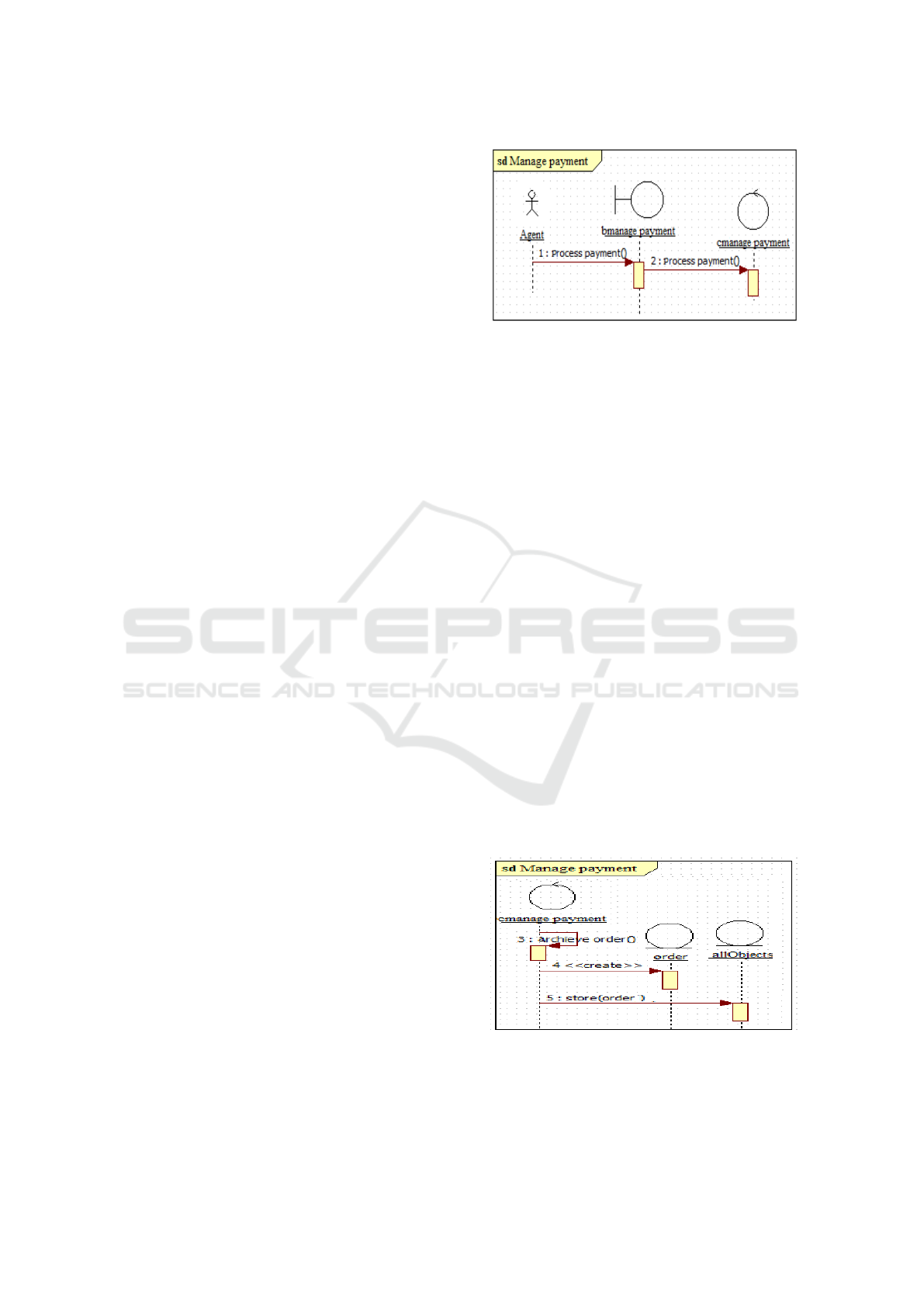
Figure 3: Example of R4.1.1 application on the user task
"process payment".
Task(created by R1).
• Create a message Task() from bdr to act
1.3. If the Task type is service, script or business
rule, then create a reflexive message Task()
from and to ctr (cf. the example in Figure 4.)
2. If Task is a reader of an IAE iae:
2.1. If the iae type is data store :
• Create a message called iae_id:search() from
the control ctr to the object allObjects (that is
created by R1)
• Create a message called iae_id:search() from
the object allObjects to the control ctr
• Apply steps 1.1, 1.2 or 1.3 (according to the
task type), and add iae_id as an argument to
the messages created in these steps.
3. If Task is a writer of an IAE prdD , then :
3.1. Apply step 1.1, 1.2 or 1.3 (according to the task
type).
3.2. Add a creation message from the control ctr to
the object prdD.
3.3. If prdD is a data store, create a message
store(prdD) from ctr to allObjects (cf. the ex-
ample in Figure 4.).
Figure 4: Example of R4.3 application on the task "Archive
order".
From BPMN to Sequence Diagrams: Transformation and Traceability
441

3.5 Transformation of Signal and
Exception Events
In BPMN, a signal event is used to send or receive a
signal which may be considered as a warning of the
system that triggers the user who might be interested
to notice and then react to that signal. In the sd, a
message kind called asynchSignal is used to specify
signals between objects (actor, control, class, bound-
ary). Accordingly, we define R5 to transform each
signal event in BPMN into an asynchSignal in sd as
follows.
R5. For each signal event SE in the fragment F:
1. Create an asynchSignal message asynM that has
the same name as SE from the control- to the
boundary lifeline that represent F.
2. Traceability: Create a link stereotyped Trace from
asynM to SE.
BPMN also defines error and cancel events, which in-
terrupt the task to which they are attached. In the sd,
a break combined fragment may specify an interrup-
tion scenario. To specify exception events in the sd,
we propose to transform each exception event into a
control and a boundary lifelines, which have the name
of the exception event. Moreover, we generate mes-
sages for triggering and handling the exception sce-
nario.
R6. For each error and cancel event:
1. Create a boundary bdrExcept and a control ctrEx-
cept lifelines, which have the exception event
name repressively preceded by the letters b and
c.
2. Add two creation messages from the control life-
line FName (that represents the fragment F) to
ctrExcept, and bdrExcept.
3. Create a Break combined fragment.
4. Create a message trigger(), in the Break combined
fragment, from the control lifeline FName to the
control lifelinectrExcept.
5. Create a reflexive message treatException() from
and to the control lifeline ctrExcept.
6. Create a message called display() from the control
lifelinectrExcept to the boundary lifeline bdrEx-
cept.
7. Traceability: Create a link stereotyped Trace
from the Break combined fragment, ctrExcept and
bdrExcept to the exception event.
5 shows an example of applying ruleR6 on the excep-
tion event materials unavailable.
BPMN defines also a compensation event in the con-
text of triggering or handling compensation that is
Figure 5: Example of R6 application on the exception event
materials unavailable.
concerned with undoing steps that were already suc-
cessfully completed. To specify this situation in the
generated sd, we define a message called cancel() that
represent the compensation scenario. This transfor-
mation is made by R7 as follow;
R7. For each compensate event:
1. Create a boundary bdrExcept and control ctrEx-
cept lifelines which have the same name as the
compensate event preceded repressively by the
letters b and c.
2. Create two creation messages from the control
lifeline FName (that represents the fragment con-
taining the compensate event) to bdrExcept, and
to ctrExcept.
3. Create two messages having the same name as the
task that precedes the compensate event, one from
ctrExcept to bdrExcept, and the other from bdrEx-
cept to ctrExcept.
4. Create a message called cancel() from ctrExcept
to FName.
5. Create a reflexive message that has the same name
as the task that goes out the compensate event in
FName.
6. Traceability: Create a link stereotyped Trace from
ctrExcept, bdrExcept to the compensation event.
3.6 Generation of Combined Fragments
Combined fragments may be generated not only from
the exception events, but also from a looping task, a
redundant task, or gateways.
3.6.1 Generation of a Loop Fragment from a
Loop Task
In BPMN, a task with looping behavior means that
the task execution may be iterated multiple times. It
is also possible to specify a maximum number of it-
eration. UML defines a loop combined fragment to
designate that the elements which belong to this com-
bined fragment must be iterated N times. Accord-
ENASE 2020 - 15th International Conference on Evaluation of Novel Approaches to Software Engineering
442

ingly, we define R8 to transform each loop task into a
loop fragment as follow;
R8. For each loop task lt;
1. Create a combined fragment comf in the sd in-
teraction that represents the fragment F incorpo-
rating lt.comf encloses all messages created from
lt(cf. R4)
2. Create an interaction operator loop of comf
3. If the number of iteration N is indicated, st the
loop max boundary to N.
4. Traceability: Create a link stereotyped Trace from
the loop combined fragment to lt.
3.6.2 Generation of Combined Fragments from
Gateways
Overall the transformation of the gateways into com-
bined fragments is specified by the transformation
rule R9. In BPMN, a decision gateway that is used
to create alternative paths within a process flow is se-
mantically equivalent to the Alt combined fragment
that represents a choice of behavior. At most, one
of the operands will be chosen. The chosen operand
must have an explicit or implicit guard expression that
evaluates to true at this point in the sd interaction.
Unlike the exclusive gateway that allows only an
alternative execution, the inclusive gateway executes
also parallel paths within a process flow. Indeed, the
evaluation to true of one condition expression of its
outgoing paths does not exclude the evaluation of the
other condition expressions. To transform this sce-
nario accurately, we propose an Alt combined frag-
ment that encloses all alternative paths of the gateway
gt as operands, and we create another operand, in
which, we create all paths which get out ofgt to rep-
resent the execution of all paths. (cf. Figure 6.). On
the other hand, the semantics of a parallel gateway al-
lows a parallel execution of tasks. It is equivalent to
the par combined fragment that represents a parallel
merge between the behaviors of the operands (R9.3).
The transformation rule R9 is defined as follows:
R9. For each gateway gt in the fragment F:
1. If gt is an exclusive gateway : Create an Alt com-
bined fragment in the sd interaction that repre-
sents F.
2. If gt is an inclusive gateway:
2.1. Create an Alt combined fragment that has as
many operands as outgoings of gt; the guard
expression of each operand in the Alt combined
fragment is the label of the corresponding se-
quence flow going out of gt.
2.2. Create another operand, and a guard. The ex-
pression of this guard represents all the outgo-
ing labels of gt.
Figure 6: Example of R9.2 application.
3. If gt is a parallel gateway, then create a Par com-
bined fragment in inter.
4. In the created combined fragment, then for each
sequence flow SF that goes out of gt create an
operand in the combined fragment that incorpo-
rates messages generated from the target ref (ex-
ception event, activities) of SF.
5. Traceability: Create a link stereotyped Trace from
the combined fragment to the gateway gt .
3.6.3 Generation and of Interaction Uses
In BPMN, many participants may execute the same
activity. Hence, the same activity may belong to dif-
ferent fragments of the same business model. In sd,
the ref combined fragment(interaction use) is used to
reference a part of a sd in another one. It represents
relationships between separate sds.
R10. For each task Task that appears in multiple
fragments, we assume that there exists a sd interac-
tion that has the name of Task and represents it.
1. Create an interaction use in the sd interaction that
represents the fragment F (that we are handling
and that contains Task). The interaction use has
the same name as Task.
2. Create an operand that has the name Ref in the
interaction use.
3. Traceability: Create a trace link stereotyped Trace
from the interaction use to Task.
In the business model, if there is an inclusive or an ex-
clusive gateway between two different fragments, this
means that the fragment that comes into the gateway
optionally extends the fragment that goes out of this
gateway. In sd, the reuse and extension principle is
possible by means of the interaction use element.
R11. Let F1 and F2 be two fragments, and there
is an inclusive/exclusive gateway gt from F1 and F2.
From BPMN to Sequence Diagrams: Transformation and Traceability
443
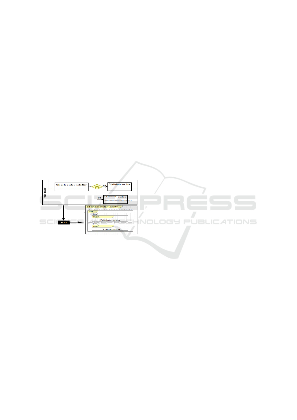
Suppose that the sd interaction of F2 is a separate sd
from the sd interaction of F1 (that we are handling),
and is already created.
1. Create an interaction use of F2 in the sd interac-
tion representing F1 to reference the reuse of sd
of F2 in sd of F1. The interaction use is called
F2Name.
2. Create an operand called ref in the interaction use
3. Create an Alt combined fragment that encloses the
interaction use.
4. Traceability: Create a link stereotyped Trace from
the interaction use and the Alt combined fragment
to gt.
In Figure 7 there is an exclusive gateway between
two fragments Check order validity and Validate or-
der, which are represented as black boxes in this Fig-
ure. The fragment Validate order goes out an exclu-
sive gateway and is specified in the interaction Check
order validity representing the fragment Check order
validity as an interaction use.
Figure 7: Example of R11 application.
4 ADVANTAGES OF OUR
APPROACH
The strong point of our approach is the complete set
of transformation rules in comparison to the exist-
ing works. Indeed, we consider many BPMN arti-
facts in our transformation rules (data store, task type,
exception and signal events), which are not consid-
ered in previous works.The generated diagram can
be used as a starting point for the software develop-
ment process as it significantly shortens the efforts
and the time needed to build sds from scratch. Our
approach considers not only sd elements but also re-
lationships between interrelated sds generated from
the same business model. Further, structuring the ob-
tained sd according to the MVC design pattern is also
a strong point of our approach. Moreover, our ap-
proach accounts for traceability. The generated trace
links may be used to help designers to reduce the
analysis time and cost to identify the misalignment
sources, and triggers them if a change is applied on
these elements. Furthermore, our approach has the
merit of accounting for both the semantic and struc-
tural aspects of both the BPMN and the UML ele-
ments, which we use without any extension. Accord-
ingly, we have explored existing plugins and tools to
implement our approach such the BPMN2modeler,
UML designer and the Atlas Transformation Lan-
guage (ATL)(Jouault and Kurtev, 2005) plugins.
5 CONCLUSIONS AND
PERSPECTIVES
In the current approach, we base on the MDA
approach, and we define BPtraceSD, a semi-
automatically transformation approach of a BPMN
bpm into sds tructured according to the MVC de-
sign pattern. This transformation allows obtaining
aligned models. Throughout the transformation pro-
cess, we define traceability links between the source
and the target model elements, which permit to main-
tain mapped elements always aligned even if they
evolve, reducing this way the analysis time to recog-
nize sources of the misalignment. An ongoing work
is oriented towards broadening the traceability man-
agement, attempting to integrate the the IS with the
business modeling.
REFERENCES
Alami, N., Arman, N., and Khamyseh, F. (2017). A
semi-automated approach for generating sequence di-
agrams from arabic user requirements using a natural
language processing tool. In 2017 8th International
Conference on Information Technology (ICIT), pages
309–314. IEEE.
Arman, N. and Jabbarin, S. (2015). Generating use case
models from arabic user requirements in a semiauto-
mated approach using a natural language processing
tool. Journal of Intelligent Systems, 24(2):277–286.
Berrocal, J., García-Alonso, J., and Murillo, J. M. (2014).
Modeling business and requirements relationships for
architectural pattern selection. In Software engineer-
ing research, management and applications, pages
167–181. Springer.
Bouzidi, A., Haddar, N., Abdallah, M. B., and Haddar, K.
(2017). Deriving use case models from bpmn models.
In 2017 IEEE/ACS 14th International Conference on
Computer Systems and Applications (AICCSA), pages
238–243. IEEE.
Brdjanin, D., Banjac, G., Banjac, D., and Maric, S. (2019).
An experiment in model-driven conceptual database
ENASE 2020 - 15th International Conference on Evaluation of Novel Approaches to Software Engineering
444

design. Software & Systems Modeling, 18(3):1859–
1883.
Canal, J., Farias, K., and Goncales, L. (2018). An al-
gorithm for distance calculation between uml se-
quence diagrams. IEEE Latin America Transactions,
16(4):1200–1205.
Cruz, E. F., Machado, R. J., and Santos, M. Y. (2015a).
Bridging the gap between a set of interrelated busi-
ness process models and software models. In ICEIS
(2), pages 338–345.
Cruz, E. F., Machado, R. J., and Santos, M. Y. (2015b). De-
riving a data model from a set of interrelated business
process models. In ICEIS (2), pages 49–59.
De Souza, F. C. and de Castro Giorno, F. A. (2015). Auto-
matic generation of sequence diagrams and updating
domain model from use cases.
Jabbarin, S. and Arman, N. (2014). Constructing use
case models from arabic user requirements in a
semi-automated approach. In 2014 World Congress
on Computer Applications and Information Systems
(WCCAIS), pages 1–4. IEEE.
Jouault, F. and Kurtev, I. (2005). Transforming models
with atl. In International Conference on Model Driven
Engineering Languages and Systems, pages 128–138.
Springer.
Kang, S., Kim, H., Baik, J., Choi, H., and Keum, C. (2010).
Transformation rules for synthesis of uml activity di-
agram from scenario-based specification. In 2010
IEEE 34th Annual Computer Software and Applica-
tions Conference, pages 431–436. IEEE.
Khan, Y. A. and Mahmood, S. (2016). Generating uml se-
quence diagrams from use case maps: a model trans-
formation approach. Arabian Journal for Science and
Engineering, 41(3):965–986.
Khlif, W., Ayed, N. E. B., and Ben-Abdallah, H. (2018).
From a bpmn model to an aligned uml analysis model.
In ICSOFT, pages 657–665.
Maciaszek, L. A. and Filipe, J. (2015). Evaluation of novel
approaches to software engineering. In 10th Interna-
tional Conference, ENASE, pages 29–30. Springer.
Nassar, H. A., Alhroob, A., and Imam, A. T. (2017). An
algorithmic approach for sketching sequence diagram
(aassd). In Proceedings of the International Confer-
ence on Advances in Image Processing, pages 156–
160. ACM.
Nikiforova, O., Gusarovs, K., and Ressin, A. (2016). An
approach to generation of the uml sequence diagram
from the two-hemisphere model. ICSEA 2016, page
155.
OMGBPMN (2013). Business Process Model and Notation
(BPMN)Version 2.0.2. OMG.
OMGMDA (2006). The Fast Guide to Model DrivenArchi-
tecture[Online]. OMG.
Salami, H. O. and Ahmed, M. (2014). Retrieving sequence
diagrams using genetic algorithm. In 2014 11th In-
ternational Joint Conference on Computer Science
and Software Engineering (JCSSE), pages 324–330.
IEEE.
Suchenia, A., Kluza, K., Jobczyk, K., Wi
´
sniewski, P.,
Wypych, M., and Lig˛eza, A. (2017). Supporting bpmn
process models with uml sequence diagrams for rep-
resenting time issues and testing models. In Interna-
tional Conference on Artificial Intelligence and Soft
Computing, pages 589–598. Springer.
Yue, T., Briand, L. C., and Labiche, Y. (2010). Automati-
cally deriving uml sequence diagrams from use cases.
Simula Research Laboratory.
From BPMN to Sequence Diagrams: Transformation and Traceability
445
