
State Validation in Automated Planning
Caio Gustavo Rodrigues da Cruz
1 a
, Mauricio Goncalves Vieira Ferreira
1 b
and Rodrigo Rocha Silva
2,3 c
1
Space Engineering and Technology, National Institute for Space Researches (INPE), S
˜
ao Jos
´
e dos Campos, Brazil
2
Centre for Informatics and Systems, University of Coimbra (CISUC), Coimbra, Portugal
3
FATEC Mogi das Cruzes, S
˜
ao Paulo Technological College, Mogi das Cruzes, Brazil
Keywords:
Planning Preference, Invalid States, PDDL.
Abstract:
The crescent number of automated systems in satellites raises several security and reliability concerns, that are
worsened with the time. Plan validation techniques were created to validate flight operation plans generated
automatically. The execution of automatically generated plans on satellite flight operations can result in de-
graded or invalid states. Verifying the possibility of removing these states of a plan through a state validation
technique is the objective of this paper. Analyzing the action that generated and, in planning time, remove the
invalid states from the plan steps enables the planner to find the final state without any invalid state. Therefore,
implementing a state validator in the automated planner prevents the plan from containing any invalid state.
1 INTRODUCTION
The concept of plan quality in automated planning is
a very important issue. In several real-world plan-
ning domains, we must address problems with a large
set of solutions, or with a set of goals that cannot be
completely achieved. Besides, in the expected solu-
tions there may be constraints during the trajectory, in
intermediary states of final state. In these cases, the
mode how the goal is reached can be more important
than the goal itself. For this reason, it is important to
generate plans of better quality achieving all problem
goals, when possible, or some subset of them (Baier
et al., 2008).
Automated planning is an AI area focused on solv-
ing problems. A planning domain is comprised of a
finite set of possible states S = {s
1
, s
2
...s
k
}, and a fi-
nite set of actions A = {a
1
, a
2
...a
k
}, applicable to the
domain states (Ghallab et al., 2004). A planning prob-
lem is originated when the need to transform an initial
state s
i
in a set of final states S
g
. The action sequence
< a
1
, a
2
, ...a
k
>, when applied in the results of the
order in the end state is called plan. A description of
the state transition system used in automated planning
follows.
a
https://orcid.org/0000-0001-6143-3908
b
https://orcid.org/0000-0002-6229-9453
c
https://orcid.org/0000-0002-5741-6897
s
1
= γ(s
i
, a
1
), s
2
= γ(s
1
, a
2
), ..., s
k
= γ(s
k−1
, a
k
)
and s
k
∈ S
g
The function γ(s, a) applies an action to a state,
resulting in a state transition system. For each gen-
erated state, an action is applied until the generated
state is corresponds to the final state. A problem can
be solved in countless ways i.e., infinite step sets can
transform the initial state in the final state (Ghallab
et al., 2004).
Automated planning is achieved using a planner
software that finds the step sequence that transforms
the initial state in the goal state (McDermott et al.,
1998). The planner uses two files as input in order
to solve a problem: The domain file, that defines the
applicable actions, and the problem file, that defines
the initial and final states.
STRIPS (Stanford Research Institute Problem
Solver) is a technique used to find solutions from
a domain and a problem (Fikes and Nilsson, 1971).
STRIPS goes through all the possible states after ap-
plying the domain actions until it finds the final state
(Fikes and Nilsson, 1971). The most common lan-
guage in automated planning is PDDL (Planning Do-
main Definition Language) introduced in 1998 by
Drew McDermott (McDermott et al., 1998).
The theme of planning is applied to many real-
world domains and issues. In the space area flight
plan generation for the control of artificial satellites
is an example of the planning application. In most
396
Rodrigues da Cruz, C., Ferreira, M. and Silva, R.
State Validation in Automated Planning.
DOI: 10.5220/0009411903960406
In Proceedings of the 22nd International Conference on Enterprise Information Systems (ICEIS 2020) - Volume 1, pages 396-406
ISBN: 978-989-758-423-7
Copyright
c
2020 by SCITEPRESS – Science and Technology Publications, Lda. All rights reserved

cases, INPE’s Satellite Tracking and Control Center
(STCC) performs its satellite control operations man-
ually. Finding solutions to flight operation automati-
zation is a challenge that can be solved with planning
(Tominaga et al., 2011).
Concern over the generation of higher quality
satellite control plans in research such as Souza’s,
suggests the creation of a diagnostic generator to val-
idate whether the automatically generated s match the
situation of the satellites in operation. The approach
considers a rejected plan if a state classified as un-
safe for the mission compose the plan of the state se-
quence, so a new plan should be generated using dif-
ferent steps to reach the goal state. The rejection of a
plan implies the generation of a new plan, with differ-
ent steps but still reaching the end state (Souza et al.,
2012). In this context, preventing some steps of be-
ing generated in the plan is a challenge to the satellite
flight operation planning domain.
The flight operation planning for satellites is com-
plex to be solved with classical planning techniques
alone, because they are not considered to be con-
straints on the transition states of a plan. This de-
ficiency open ways for many surveys’ themes in AI
planning, for example, the planning with constraints,
with user preferences, of complex problems and about
uncertainty. These themes are found in literature in
works that create new planning languages, techniques
or implement planners to meet specific constraints of
the planning problem.
How seen if the use of the classical planning
based in STRIPS been used to solve these prob-
lems, the generate of plans without consider con-
straints in satellite domain, can create invalid plans.
An approach that eliminate specific states of solution
planned of automatic form is the motivation this work
for solve the problem in question.
The goal is to propose a solution based on clas-
sical planning that incorporates and considers at the
time of planning states that are degraded and should
not be part of the plan state sequence. In this paper,
it is proposed to create a new method in a STRIPS-
based scheduler that validates the states at planning
time. The proposal creates a filter of states that can-
not compose the solution. Thus, contributing to valid
plans can be automatically generated using a planner.
The strategy in this paper is how to find a valid plan
in classic planning.
Our intention to show that the automatic plan-
ning of satellite plans should be concerned specifi-
cally with the states that make up a plan. And that
classical planning can be used to solve this kind of
problem if you know the states that the plan should
avoid. Our approach envisions mapping these states
and incorporating them into the planner.
In works found in the literature, the creation of
new languages is common to solve more complex
planning problems. Most of these works are related
to planning with preferences, which is an area that
has been extensively studied in recent years. In the re-
lated works session, we present the works with differ-
ent techniques and planning methods that were pro-
posed in different areas, to create increasingly better
solutions in different domains.
About the solution: In this article we will demon-
strate a way to generate step constrained plans using
as an example a didactic planning problem to validate
the implementation of a validator method in a planner.
In the first step prove that at planning time it is
possible to disregard the degraded states by creating a
new input in the planning domain. The new entry will
be read and used in the planner to build a solution
that meets the constraints required by the domain. In
future research a model will be created to represent
the states and convert them to a planner entry.
The rest of this paper is structured as follows:
Section 2 describes the methodology used; Section 3
presents the results of the tests solving the automated
planning for the blocks world problem; Finally, sec-
tion 4 presents the conclusions and some future work.
2 RELATED WORK
We found different works on AI planning that address
issues such as quality plan generation, complex plan-
ning problems, uncertainty planning and user prefer-
ences in planning. Among these approaches a com-
monly used term is preferences, an interdisciplinary
topic found not only in AI, but in studies with differ-
ent perspectives and areas (Domshlak et al., 2011).
The works found on planning that address the
theme of preferences are (Boutilier et al., 1999)
(Gerevini and Long, 2006) (Tu et al., 2007) (Baier
et al., 2008) (Sohrabi et al., 2009). Among these
works are several approaches such as planner devel-
opment, language creation, implementation of tech-
niques in existing planners, extension of planning lan-
guages and combination of techniques are used to
meet preferences in the planning context.
PBP preference-based planning aims to find more
preferred plans in a planning instance. Criteria are
provided to determine when one plan is more pre-
ferred than another. Preferences are modeled accord-
ing to language type and can be either quantitative or
qualitative. In order to compare when a plan is pre-
ferred in the quantitative approach a numerical func-
tion is used to an ever-induced overall relationship.
State Validation in Automated Planning
397

In qualitative language the comparison is in terms of
property without number assignment. There are also
approaches with the combination of qualitative and
quantitative languages (Jorge and Sheila, 2008).
The search for the construction of ideal or near op-
timal plans is a theme addressed in Boutilier’s work.
Decision-Theoretic planning uses the Markov Deci-
sion Process (MDP) to explore policy making and
idea plans. MDP associates a reward function with
each state transition, thereby defining user prefer-
ences. All possible states are classified quantitatively,
and an action is returned depending on the execution
history (Boutilier et al., 1999).
The approach used in Partial Satisfaction Planning
offers resources to partially solve problems, reaching
a subset of objectives. To partially solve the plan-
ning problems, techniques based on heuristics were
developed. The techniques used are concerned with
the quality of the plan, contributing to generate plans
with low cost and compatible with the quality of plans
from other approaches (Briel et al., 2004).
In the work of Baier et al (2008) a method was
created to compile a planning instance and a control
procedure into a classic planning instance represented
in PDDL. The compilation allows to represent in the
planning domain the procedure as a finite state au-
tomaton. The representation is made from an addi-
tional predicate that modifies the effects and precon-
ditions of the actions, allowing the procedure to be
respected (Baier et al., 2008). For planning with pref-
erences Baier et al (2008) proposes to use the rela-
tionship between linear temporal logic and automata.
The temporal LPP language is used to express pref-
erences through temporal properties of states and ac-
tions by qualitatively classifying expressions (Baier
et al., 2008).
2.1 The PDDL Language
Based on Lisp syntax, the PDDL LANGUAGE uses
a structure based on the widely used variants of strips
notations. Establishing a common standard language
has had a similar impact on planning research as the
introduction of standards in other areas of research: it
opens the route to stronger collaboration, exchange
of tools, techniques and problems and provides a
platform for comparative evaluation of approaches.
The language has been, since the beginning, strongly
linked to the competition series, with developments
in the language being drivers for the direction of the
competition challenges.
PDDL has been extended in several stages in or-
der to capture more expressive variants. There have
been several explorations of the expressive power of
the different variants of PDDL. Recent results include
a demonstration that temporal features can be com-
piled away in polynomial work, subject to certain
constraints on the forms of concurrency that can ap-
pear in the problem (Rintanen, 2007), while others
have examined the compilability of conditional ef-
fects, timed initial literals and domain axioms (Nebel,
2000), (Fox et al., 2004), (Thi
´
ebaux et al., 2005).
In reference (Gerevini and Long, 2005) and
(Gerevini and Long, 2006) extended the PDDL lan-
guage to a PBP language. PDDL3 uses Hierarchical
Task Network (HTN) to include up to three types of
preferences, increasing the expressive power over the
plan’s quality specification. The first is the ability to
express goals that apply not only to the final state of
the trajectory of states visited by a plan, but also to
the intermediate states. These goals take the form of
trajectory constraints, familiar from work on temporal
logics.
Both extensions to the language are motivated by
the desire to see planning bridge the gap between
research and application. Many real problems re-
quire the specification of goals that are more com-
plex than be easily expressed in earlier versions of
PDDL. These include constraints on the states (or in-
valid state) that a plan visits as well as on the state in
which it finishes. It can also be important to specify
the relative benefits of different, perhaps conflicting,
desirable conditions that a plan should satisfy, so that
a plan might be constructed to evaluate these benefits
against the costs of achieving them.
Table 1: Comparative table of approaches with preferences.
Approuch Technique Preference
PDDL3
Hierarchical
Task Network
Violated prefer-
ences metric
MDP
Reward func-
tion
Classification
based on the
history of actions
performed
PSP Heuristics
Planning with
subset of objec-
tives
Control
Procedure
Method
Temporal
Linear Logic
and Automata
Additional predi-
cate on the effects
of actions
Table 1 presents a comparison between planning ap-
proaches with preferences. It is considered the tech-
nique used and how the preferences are models. It is
understood that each approach includes preferences
in planning differently and to meet specific require-
ments.
ICEIS 2020 - 22nd International Conference on Enterprise Information Systems
398
3 STRATEGY TO VALIDATE
INVALID STATES IN
PLANNING TIME
A hypothesis was created for automatic plan genera-
tion that are composed of steps that do not include any
invalid states to achieve an objective. The hypothesis
is that valid plans can be generated if invalid states are
validated in the planner in planning time. Therefore,
if the planner finds the end state using a step sequence
that transits only through valid states in the domain,
the strategy is valid.
The planner applies in the initial state the actions
defined in the domain and creates a state tree while the
actions are applied. However, in planning time, when
an action is applied on the current state, the planner
knows what is going to be the state that will be added
to the state tree. The moment a domain action is ap-
plied to the current state, the new generated state can
be validated before composing the state list that the
planner uses to find the final state. The implementa-
tion of a state validator in the planner will enable the
identification of generated invalid states in planning
time.
A planning problem can be understood from the
following representation: P = (Σ, s
i
, S
g
), where Σ is
the state transition system, s
i
is the initial state and S
g
is a set of the goal states. In the concept of classical
planning, a plan is not deterministic and there may be
different ways of finding the sequence of actions that
transform the initial state S
i
into the objective state
S
g
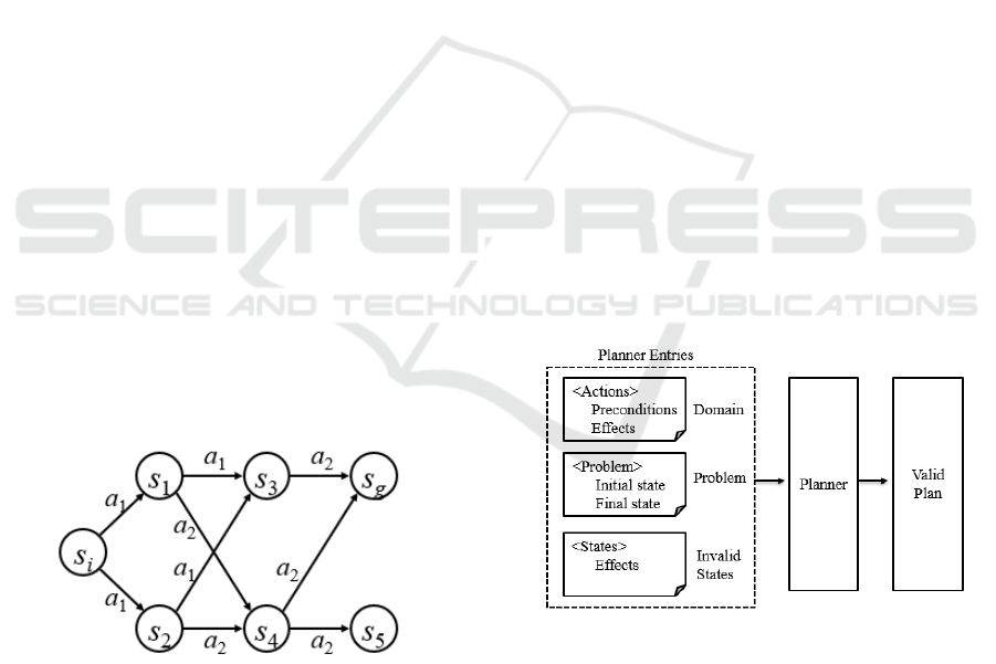
. Figure 1 represents a non-deterministic state tran-
sition system in which the objective state S
g
can be
achieved using different paths.
Figure 1: Non-deterministic state transition system.
The characteristic presented in the non-deterministic
state transition system allows a planning problem to
be solved using different paths. States can be easily
ignored and the objective state can still be reached.
Allowing thus to ignore states that should not be part
of the solution, the planner will find paths without
passing through such states.
What can set a state to invalid for a domain? In
planning a state is composed of first order atoms that
are represented as propositions. Objects that consti-
tute the state can be presented as constant, variable,
or function terms. However, in the planning domain it
may contain some rule that invalidates a state accord-
ing to the configuration of atoms, be it the location or
actions that relate one or more atoms thus indicating
that the state is invalid. In the satellite control domain,
for example, the domain is constantly changing due to
external environmental conditions that degrade satel-
lite subsystems. When a degradation occurs a new
invalid state is added to the domain. The invalid state
is a prohibited, degraded or risky scenario for the do-
main’s operation.
The example used in the experiment in this article
restricts one of the cranes from unloading a specific
container, thus representing an invalid state, when
the ”unloading” actions are associated with these two
atoms.
For the generation of valid plans, a strategy was
created so that invalid states about the domain are
considered. The planner will have as its input the do-
main and problem files, as well as another file con-
taining the definitions of invalid states for the domain
in question as shown in the Figure 2. The invalid
states defined as the new input will be used to validate
the generated states in planning time, consequently,
when a new state is generated, it will be compared
with the invalid state list and the planner will then ig-
nore the invalid state and won’t add it to the solution
tree.
Figure 2: Represent strategy.
To formalize the implementation of the proposed
strategy, we modified the concept of problem previ-
ously defined as P = (Σ, s
i
, S
g
), to then use the func-
tion V (s
k
, I) responsible for validating and filtering
the states in time, where s
k
represents the current state
and I represents the instance of invalid states previ-
ously configured as input to the planner. The mod-
ification transforms the standard function as follows
P = (Σ, s
i
, S
g
,V (s
k
, I)).
In order to validate our plan generation method,
State Validation in Automated Planning
399
we chose the automated planner AI Planning with
STRIPS (Becker, 2015). This planner is a demo
project for the STRIPS automated planner library
written in NodeJS (Becker, 2015).
Initially we chose a simple planning problem to
formulate an example of using the strategy to validate
states. The blocks world problem is a classic planning
problem, it consists in stacking blocks on top of tables
in some arbitrary order (Gupta and Nau, 1991). Some
actions of this domain are moving a block from one
table to another, stacking two blocks and unstacking
two blocks. After implementing the validator method,
another planning problem was chosen to validate a
scenario with a larger number of states.
The development of this work followed four
stages: choosing the planning problem, generating the
invalid state file in PDDL, modifying the planner to
load the invalid states and implementing a state vali-
dation function in the planner.
3.1 Strategy Application in an Invalid
State
The problem of the chosen block world consists of six
objects, three blocks and three tables. The initial state
has blocks a, b and c in this block c on block b, block
b on block a and block a stacked-on top of table t1
and other two tables, t2 and t3, empty. The goal state
is comprised of the blocks in the reverse order block a
on block b, block b on block c and block c over table
t3, as shown in the Figure 3.
Figure 3: Planning problem.
The planner must find an action sequence that is able
to transform the initial state in the goal state using
only the actions defined in the problem domain, for
instance: move – moves a block from one table to
another; stack2 – stacks a block over another block
in another table; stack3 – stacks a block over another
two blocks over another table; unstack2 – unstacks
two blocks, putting the unstacked block over an-
other, empty, table; unstack3 – unstacks three blocks,
putting the unstacked block over another, empty, ta-
ble.
This problem was executed in the planner and a
plan was used. A state transition that the planner
encountered is shown in Figure 4. It can be viewed
as a sequence of domain actions that were applied to
states until the goal was reached. The first action ap-
plied was unstack3, responsible for unstacking three
blocks, resulting in unstacking or block c from block
b to a table t3.
Figure 4: State transaction.
After representing the execution of the plan, we ran-
domly choose one of the traversed states to represent
an invalid state. The state chosen was that generated
by applying action 2. Unstack2. The chosen state was
set in a new file written in PDDL as shown in Figure
5.
Figure 5: Invalid state file written in PDDL.
The state was configured as a common action, using
the same definitions of the domain file in PDDL. In
the invalid1 (Figure 5, line 3) configuration we de-
fined its parameters as its variables: three blocks and
ICEIS 2020 - 22nd International Conference on Enterprise Information Systems
400
three tables. Positioning and order are defined in the
effects, as in block a over table t1 - (on ?a ?t1), block
a free (clear a), block b over table t2- (on ?b ?t2),
block b free (clear b), block c over table t3 - (on ?c
?t3) e block c free (clear c).
The planner has a PDDL file reading function, re-
ceiving as its parameter the file path and loading the
file in memory. We used the existing implementa-
tion to read the invalid state file. The StripsMan-
ager.loadDomain() (Figure 6, line 4) function was
reused to load the new invalid state file.
Figure 6 shows our modifications to the load func-
tion: we added the invalidStatePath parameter in
function.
Figure 6: Invalid state file loading method.
After loading the invalid states, an object containing
all the invalid states definitions was added to a new in-
validState property in the domain object. The domain
object is the main parameter for the planner methods,
since it contains the actions used in the plan.
The code snipped where the planner applies the
actions, generating new states is shown in Figure 7
The getChildStates method (Figure 7, line 1) is re-
sponsible for applying the actions to the current plan
state. The method has as its parameters the domain
definition and the current plan state.
Figure 7: Generating method of new states.
How is an action applied to the current state The ap-
plicableActions method (Figure 7, line 4) iterates all
the actions in the domain passed as parameter, veri-
fying if their preconditions are met – i.e. the current
state corresponds to the precondition. The quantity of
applicable actions is the same as the number of gener-
ated states. For each action iterated a new state is gen-
erated by the applyAction (Figure 7, line 9) method.
The effects of the execution of an action on a state are
defined by the action effects, defined in the domain.
The method iterates the effect list and modifies the
current state, adding and removing parts of the state
according to the operation, e.g. the action unstack2 is
applied to the state (on a t1) (on b a) (on c t3) (clear t2)
in the following manner: each part of the current state
is compared to the effect parts defined in the unstack2
action.
Figure 8: Data structure representing an effect.
Figure 8 shows the structure of the unstack2 effect.
Therefore, the method verifies each effect part and if
the operation property is “and”, that part is added to
the current state. If the operation is “not”, the part is
removed from the current state. The action results in
the state (on a t1) (on b t2) (on c t3) (clear a).
After generating a new state, the stateValidator
method was included in the implementation to check
if the generated state is a valid state. The stateVal-
idator method receives as parameter the invalidState
definition we included in the domain object and the
generated newState. The validator returns true if the
hew state is identical to any configured invalid state.
Only valid states can be added to the child state list.
3.2 Implementing the Invalid State
Validator
The planner invalid state validator function is shown
in Figure 9 compares the states configured in the in-
valid state file and the states created in planning time
to compose the plan.
The validator function is shown iterates over three
loops in order to validate the states. The first loop
goes through the list of invalid states configured in the
State Validation in Automated Planning
401

Figure 9: State validator function.
file, since there can be more than one invalid state.
The second loop iterates each of the invalid state’s
parts, e.g. the state (on a t1) (on b t2) (on c t3) is
composed of three parts: in the first iteration, the part
(on a t1) will be compared. The third loop iterates the
new state’s parts and compares them.
The data structure that abstracts a single part of
a state comprises three properties. The action prop-
erty (Figure 9, line 9) represents the association be-
tween the parameters defined in the parameter’s prop-
erty (Figure 9, line 12) and the operation parameter
(Figure 9, line 8) indicates whether the relation exists
in that state. When operation is not, the relationship
doesn’t exist and there is no need to compare the cor-
responding part with the invalid state part.
The state comparison is comprised of three con-
ditions: if operation is not negative, if the action of
both parts is the same and if both parts’ parameters
are identical. The arraysIdentical function is present
in the planner implementation, responsible for com-
paring both states’ parameters, verifying if their size
and values are equal. Figure 9 shows a full implemen-
tation of the stateValidator function.
In the second loop (Figure 9, line 5), the equal-
State variable (Figure 9, line 6) is set as false, sug-
gesting that the part wasn’t found in the new state yet.
In case the third loop doesn’t find an equal part and,
when it’s finished, the equalState variable is (Figure
9, line 18) still false, the break command (Figure 9,
line 19) is called, since there is no need to continue
comparing the parts of that invalid state.
When the condition is met, there is a part of the
invalid state in the new state. The equalState vari-
able (Figure 9, line 14) is set as true and the break
command (Figure 9, line 15) is called, exiting the in-
ner loop and iterating over the next invalid state. In
case there are no more parts in the loop and the equal-
State variable (Figure 9, line 21) is true, another break
command (Figure 9, line 22) is called since there is
no need to continue searching the invalid state list.
Finally, the algorithm returns the value of equalState
(Figure 9, line 24).
4 RESULTS
In this section we present the results obtained by test-
ing the implementation of the state validator method
in the planner. Planning was performed for several
plans, which included invalid states to be tested in the
planner.
Figure 10: Dock worker robot problem.
We chose the dock worker robot problem for testing
because it is a more complex problem than the block
world and uses more objects and actions in the plan-
ning domain. The problem is to move three contain-
ers between two different locations, using cranes and
a robot to transport them as shown in Figure 10.
The problem has two locations in the initial state
l1 and l2. At location l1 there are two pile p1 and q1,
a crane k1 and three containers ca, cb and cc stacked
over pile p1. At location l2 has a pile p2 and two
cranes k2 and k3. The initial state configuration and
arrangement of problem objects has been arranged to
enable the inclusion of invalid states for the test.
The purpose of the problem is to move the con-
tainers to location l2. The domain file includes the
following functions: move - moves a robot between
two adjacent locations; load - loads an empty robot
with a container held by a nearby crane; unload - un-
loads a robot holding a container with a nearby crane;
takes - takes a container from a pile with a crane; put
- puts a container held by a crane on a nearby pile.
The problem was executed in the planner and a
ICEIS 2020 - 22nd International Conference on Enterprise Information Systems
402
seventeen-step plan was generated to solve the prob-
lem. Table 2 shows the transition from initial state Si
to objective status Sg, including the sequence of ac-
tions required to move containers from location l1 to
location l2 in the plan I.
Table 2: Representation of the plan I states.
Action State Representation
Init Si
Containers stacked
on site 1
1. take k1 l1
cc cb p1
S1
Crane k1 grabbed the
cc container
2. load k1 l1
cc r1
S2
Robot r1 was loaded
with cc container
3. move r1 l1
l2
S3
The robot has been
moved to location l2
4. unload k2
l2 cc r1
S4
The crane also un-
loaded the cc con-
tainer
5. move r1 l2
l1
S5
Robot r1 has been
moved to location l1
6. take k1 l1
cb ca p1
S6
Crane k1 took con-
tainer cb
7. load k1 l1
cb r1
S7
Robot r1 was loaded
with container cb
8. move r1 l1
l2
S8
Robot r1 has been
moved to location 2
9. unload k3
l2 cb r1
S9
Crane k3 unloaded
container cb
10. move r1
l2 l1
S10
The robot has been
moved to location l1
11. take k1 l1
ca pallet p1
S11
Crane k1 took con-
tainer ca
12. load k1 l1
ca r1
S12
Robot r1 was loaded
with container ca
13. move r1
l1 l2
S13
The robot has been
moved to location l2
14. put k3 l2
cb pallet p2
S14
Crane k3 placed con-
tainer cb on pallet
15. unload k3
l2 ca r1
S15
Crane k3 unloaded
container ca
16. put k3 l2
ca cb p2
S16
Crane k3 placed con-
tainer ca on cb
17. put k2 l2
cc ca p2
S17
Crane k3 placed con-
tainer cc on ca
The test consisted of choosing one of the states gen-
erated in plan I to represent an invalid state. We
note that during state transition the ca container is
unloaded by crane k3 at location l2. Suppose there
is a rule in the transport domain of these containers
that prevents crane k3 from loading the ca container
for some reason. So we determined that the first in-
valid state of this domain is “Crane k3 unloading the
ca container”.
Looking at Table 2 state S15 is the state chosen
as invalid. This means that action 15 - unload k3 l2
ca r1 contains the effect responsible for generating
the invalid state. So, to create the invalid state file in
PDDL, you must use the unload action effect defini-
tion defined in the planning domain file. The effect
is represented as follows: effect (and (unloaded? R)
(holding? K? C)).
The effect definition will be used to map the in-
valid state. The effect parameters are changed to the
names used in the problem. So, define the effect as:
effect (and (unloaded? r1) (holding? k3? ca)), indi-
cating that k3 is holding the ca container as shown in
Figure 11.
Figure 11: Invalid state definition.
The problem was rerun in the scheduler using the in-
valid state validator method. Plan II was created with
different actions to find the objective state, thus fulfill-
ing the restriction added to the states. Table 3 shows
the action it was generating, or the invalid state is no
longer present in plan II. Action 16. unload k2l2 ca
r1 detects that the container is now loaded by crane
k2.
Figure 12: Invalid state definition.
After proving that the planner generated another plan
State Validation in Automated Planning
403

Table 3: Representation of the plan states.
Action State Representation
Init Si
Containers stacked
on site 1
1. take k1 l1
cc cb p1
S1
Crane k1 grabbed the
cc container
2. load k1 l1
cc r1
S2
Robot r1 was loaded
with cc container
3. move r1 l1
l2
S3
The robot has been
moved to location l2
4. unload k3
l2 cc r1
S4
The crane also un-
loaded the cc con-
tainer
5. move r1 l2
l1
S5
Robot r1 has been
moved to location l1
6. take k1 l1
cb ca p1
S6
Crane k1 took con-
tainer cb
7. put k1 l1 cb
pallet q1
S7
Crane k1 placed con-
tainer cb on pallet
8. take k1 l1
ca pallet p1
S8
Crane k1 grabbed the
ca container
9. load k1 l1
ca r1
S9
Robot r1 was loaded
with container ca
10. move r1
l1 l2
S10
The robot has been
moved to location l2
11. unload k2
l2 ca r1
S11
The crane also un-
loaded the ca con-
tainer
12. move r1
l2 l1
S12
The robot has been
moved to location l1
13. take k1 l1
cb pallet q1
S13
Crane k1 grabbed the
cb container
14. load k1 l1
cb r1
S14
Robot r1 was loaded
with cb container
15. move r1
l1 l2
S15
The robot has been
moved to location l2
16. put k2 l2
ca pallet p2
S16
Crane k2 placed con-
tainer ca on pallet
17. put k3 l2
cc ca p2
S17
Crane k3 placed con-
tainer cc on ca
18. unload k3
l2 cb r1
S18
The crane also un-
loaded the cb con-
tainer
19. put k3 l2
cb cc p2
S19
Crane k3 placed con-
tainer cb on cc
with different actions and found the objective state.
We have included other invalid states in the file to test
further restrictions. Figure 12 shows the configuration
of the five invalid state configurators for this problem.
In the invalid state invalid1, invalid2 and invalid3
we add restrictions on the cranes in location l2. Where
invalid1 restricts crane k3 from unloading the ca con-
tainer, invalid2 restricts crane k2 from unloading the
cc container and invalid3 restricts crane k2 from un-
loading the container cb. The invalid state invalid4
adds a different condition, which restricts the ca con-
tainer to be over the cc container, and invalid5 re-
stricts the cc container to the top of the container
stack.
The relation between the plan actions and the gen-
erated state transitions is shown on Table 2. The re-
sults obtained with the state validator function were
successful, since the state mapped is not present in
the resulting plan.
The planner considered the invalid state in plan-
ning time when generating the new plan. A planning
problem can be solved in different manners, using dif-
ferent steps. E.g. the blocks world problem can be
solved in an almost infinite stack permutation.
The planning problem was submitted to the plan-
ner 5 times. In all the tests, the state validator function
worked, always generating plans that do not include
any of the invalid states.
4.1 Contributions of this Work
Our state validation method proved it is possible to
generate plan solutions even when domain constraints
exist. Automated planning for space sciences can
benefit from our finding.
Figure 13 shows a possible approach for generat-
ing valid plans for satellite operation.
This approach for valid plan generation is com-
prised of three levels. In the first (layer 1), the de-
graded states in the context of satellite operation are
inserted by specialists or by a data mining process in
a degraded state database. The second level (layer 2)
will convert the degraded states found in the previous
process to invalid states written in PDDL. The invalid
states are then used in the third level (layer 3) as input
to the planner software.
Thus, as new satellite states are being degraded
by time, plans are automatically being generated and
validated, containing no degraded states.
5 CONCLUSIONS AND FUTURE
WORK
The execution of automatically generated plans on
satellite flight operations can result in degraded or in-
valid states. Avoiding these states is possible through
state validation, as described in this work and there-
fore, problems in generated plans can be avoided
completely.
ICEIS 2020 - 22nd International Conference on Enterprise Information Systems
404
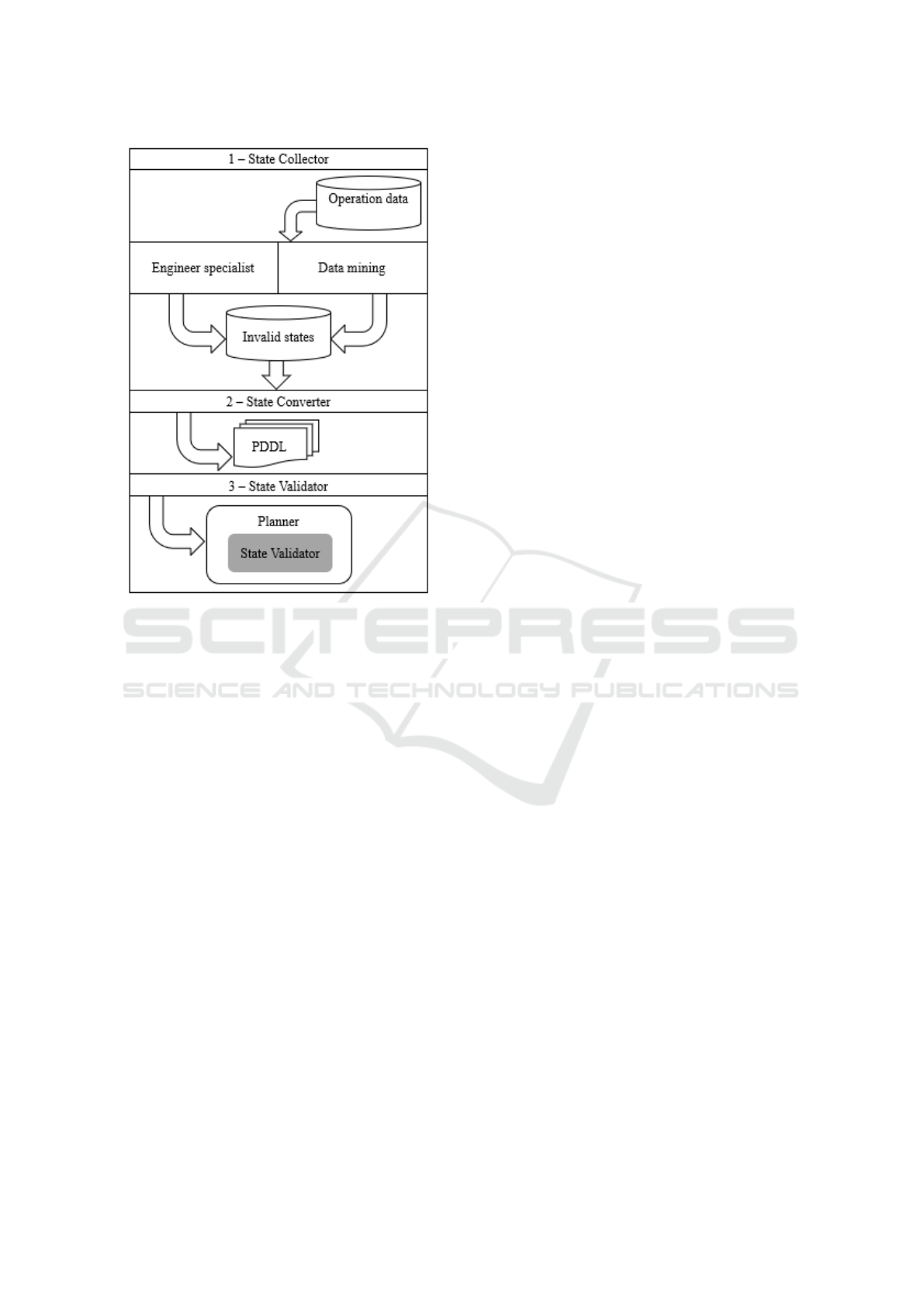
Figure 13: Approach to generating plans.
It is possible to generate plans that do not include cer-
tain states identified as invalid, as described in this
paper, by implementing a state validator. A list of in-
valid states can be read by the planner, identifying ac-
tions that will be ignored when generating the plans.
We concluded that the implementation of a val-
idation algorithm in the planner is needed at plan-
ning time to verify the actions included in the solution
stack. While the planner generates the solution to find
the end state, the validator verifies and compares the
possible resulting states of the actions. If an action
can generate an invalid state, it is discarded from the
solution stack.
In future work, we intend to develop a technique
able to convert invalid states to PDDL. A conversion
algorithm will allow the generation of planning do-
mains with preconfigured invalid states. The database
and the data structure used to persist the domain in-
valid states are also challenging.
ACKNOWLEDGEMENTS
This work was partially supported by MURALIS
TECNOLOGIA (www.muralis.com.br).
REFERENCES
Baier, J., Fritz, C., Bienvenu, M., and McIlraith, S. (2008).
Beyond classical planning: Procedural control knowl-
edge and preferences in state-of-the-art planners. In
AAAI.
Becker, K. (2015). Ai planning with strips copy-
right (c) koly becker. In Available in:
https://github.com/primaryobjects/strips.
Boutilier, C., Dean, T., and Hanks, S. (1999). Decision-
theoretic planning: Structural assumptions and com-
putational leverage. In Journal of Artificial Intelli-
gence Research, v. 11, p. 1-94.
Briel, M. V. D., S., R., Minh, M. D., and Kambhampati, S.
(2004). Effective approaches for partial satisfaction
(over-subscription) planning. In Proceedings of the
19th national conference on Artifical intelligence.
Domshlak, C., Hullermeier, E., Kaci, S., and Prade, H.
(2011). Preferences in ai: An overview.
Fikes, E. and Nilsson, J. (1971). Strips: A new approach to
the application of theorem proving to problem solv-
ing. In Stanford Research Institute, Menlo Park, Cali-
fornia.
Fox, M., Long, D., and Halsey, K. (2004). Complexity of
concurrent temporal planning. In Proc. of 17th Int.
Conf. on Automated Planning and Scheduling.
Gerevini, A. and Long, D. (2005). Plan constraints and pref-
erences in pddl3. In Technical Report RT-2005-08-47.
Dipartimento di Elettronica per l’Automazione, Uni-
versit
´
a di Brescia.
Gerevini, A. and Long, D. (2006). Preferences and soft
constraints in pddl3. In ICAPS workshop on planning
with preferences and soft constraints, p. 46-53.
Ghallab, M., Nau, D., and Traverso, P. (2004). Auto-
mated planning-theory and practice. In chapter 1. El-
sevier/Mogan Kaufmann. Elsevier.
Gupta, N. and Nau, D. (1991). Complexity results for
blocks-world planning. In AAAI-91.
Jorge, A. and Sheila, A. M. (2008). Planning with prefer-
ences. In AI Magazine.
McDermott, D., Ghallab, M., Howe, A., Knoblock, C.,
Ram, A., Veloso, M., and Wilkins, D. (1998). Pddl-
the planning domain definition language-version 1.2.
In Yale Center for Computational Vision and Control.
Nebel, B. (2000). On the compilability and the expres-
sive power of propositional planning formalisms. In
Journal of Artificial Intelligence Research 12 (2000)
271–315.
Rintanen, J. (2007). Complexity of concurrent temporal
planning. In Proc. of 17th Int. Conf. on Automated
Planning and Scheduling.
Sohrabi, S., Baier, J., and Mcilraith, S. (2009). Htn planning
with preferences. In Twenty-First International Joint
Conference on Artificial Intelligence.
Souza, P., Ferreira, M., and Silva, S. (2012). A mathemat-
ical model to predict operating states of satellites. In
ESPACEOPS.
Thi
´
ebaux, S., Hoffmann, J., and Nebel, B. (2005). In de-
fense of pddl axioms, artificial intelligence 168 (2005)
38–69.
State Validation in Automated Planning
405

Tominaga, J., Ferreira, M., and Silva, J. (2011). A rule-
based satellite simulator for use in flight operations
planning. In Journal of Computational Interdisci-
plinary Sciences.
Tu, P., Son, T., and Pontelli, E. (2007). Cpp: A constraint
logic programming-based planner with preferences.
In International Conference on Logic Programming
and Nonmonotonic Reasoning, p. 290-296. Springer,
Berlin, Heidelberg.
ICEIS 2020 - 22nd International Conference on Enterprise Information Systems
406
