
A Novel Approach for Repairing Reconfigurable Hierarchical Timed
Automata
Roufaida Bettira
1
, Laid Kahloul
2
and Mohamed Khalgui
1,3
1
National Institute of Applied Sciences and Technology (INSAT), University of Carthage, Tunis 1080, Tunisia
2
LINFI Laboratory, Computer Science Department, University of Mohamed Khider, Biskra, Algeria
3
School of Electrical and Information Engineering, Jinan University (Zhuhai Campus), Zhuhai 519070, China
Keywords:
Discrete Event Control System, Timed Automata, Modeling and Verification, Repair, Mutation,
Reconfiguration.
Abstract:
Timed Automata (TA) is a formalism for formal modeling and verification of systems with temporal require-
ments. Reconfigurable hierarchical timed automata (RHTA) extend TA to cover reconfigurability and hier-
archy of large reconfigurable discrete event control systems (RDECS). After formal modeling of an RDECS
with RHTA, formal verification against functional properties is done using model-checker. In the case of
non-satisfaction of a property, the model-checker generates a counterexample. Mostly, non-satisfaction of a
functional property is owing to incorrect clock constraints (guards and invariants). In this paper, we propose
an approach based on mutation testing for repairing the faulty RHTA model so that the concerned functional
property be satisfied. First, the hierarchy structure of each configuration is tested and repaired. Then, the
generated counterexample is used to repair the wrong guards specified in TA models which are constructing
the RHTA model. Experimentation shows that the proposed approach is able to repair a considerable part of
the RHTA model designed initially.
1 INTRODUCTION
Hierarchical RDECSs have hierarchical changeable
structures and behaviors over time. Reconfiguration
is required either to respond to requirements by users
or to handle unexpected hardware malfunctions. Hi-
erarchical modeling is useful since it is applicable to
real-life embedded systems, it specifies large systems
in different levels and it allows the reuse of compo-
nents. To introduce reconfigurability and hierarchy to
TA models, the extension reconfigurable hierarchical
timed automata (RHTA) is proposed in (Bettira et al.,
2019). RHTA is a structure of hierarchical behavior
graphs where each graph is constituted of basic com-
ponents (TA models) and it represents a configuration.
A behavior graph is reconfigured to another one by
applying reconfiguration functions.
Verification of required properties is done using
a model-checker which receives two inputs, the sys-
tem model and the set of properties to be checked
specified in a temporal logic such as computational
tree logic (CTL) (Boucheneb et al., 2009). Formal
verification is the most reliable validation activity for
RDECSs. However, it does not include a repairing
process that fixes the initial design in the case of non-
validation.
There are several works on testing timed automata
(and its extensions) (Springintveld et al., 2001), (Hes-
sel et al., 2008), and (Luthmann et al., 2019) how-
ever, the reparation of these models is not widely han-
dled. In (Nielsen and Skou, 2003), the test genera-
tion from timed automata is automated. In (Aichernig
et al., 2013), model-based mutation testing is intro-
duced. Authors in (Aichernig et al., 2014) combine
model-based mutation, classical mutation testing, and
model-based debugging to propose a methodology for
mutation-based debugging of real-time systems. In
(Aichernig et al., 2015), several optimizations of a
symbolic conformance checker are proposed using
constraint solving techniques to solve the state space
explosion problem. The work (Arcaini et al., 2019)
on software product lines proposes an evolutionary
approach to obtain a new feature model that captures
the given requested changes from existing products.
Repairing Timed automata is explicitly handled in
(Andr
´
e et al., 2019). The authors propose a repairing
process using abstraction and testing. The process in-
cludes six steps for repairing TA clock guards. One
398
Bettira, R., Kahloul, L. and Khalgui, M.
A Novel Approach for Repairing Reconfigurable Hierarchical Timed Automata.
DOI: 10.5220/0009408503980406
In Proceedings of the 15th International Conference on Evaluation of Novel Approaches to Software Engineering (ENASE 2020), pages 398-406
ISBN: 978-989-758-421-3
Copyright
c
2020 by SCITEPRESS – Science and Technology Publications, Lda. All rights reserved

of these steps is the generation of constraints which is
an expensive phase.
To the best of our knowledge, no previous work
has dealt with RHTA repairing. In this paper, we pro-
pose a novel approach for repairing the initial RHTA
designed for a hierarchical RDECS. First, the hier-
archy structure of each configuration is tested and re-
paired. Then, basic components of each configuration
which are verified against a set of functional proper-
ties are tested and repaired (i.e., correction of time
constraints). Finally, the reconfiguration automaton
of the whole RHTA is repaired. The approach is based
on mutation testing and the generated counterexam-
ple from the RHTA verification stage. The approach
is able to partially repair incorrect models in a reason-
able time considering the large size of RHTA models.
The remainder of this paper is organized as fol-
lows. Section 2 presents the background concerning
the extension RHTA. Section 3 provides an approach
for the reparation of RHTA models. Section 4 applies
and evaluates the proposed contribution. Finally, Sec-
tion 5 concludes this paper.
2 BACKGROUND
Before we introduce our approach, some basic defini-
tions are briefly recalled in this section.
2.1 Timed Automata
A timed automaton as reported in (Bengtsson and Yi,
2003), (Bouyer et al., 2008) is formally defined as A=
(L, l
0
, C, Σ, E, Inv) where (i) L is a set of locations, (ii)
l
0
∈ L is the initial location, (iii) C is a set of clocks,
(iv) Σ is a set of input, output, and internal (denoted
τ) actions, (v) E ⊆ L × Σ × B(C) × 2
C
× L is a set of
edges between locations with an action, a guard, and
a set of clocks to be reset, and (vi) Inv : L → B(C)
assigns invariants to locations.
The semantics of TA (Bengtsson and Yi, 2003),
(Bouyer et al., 2008) is given through a transition sys-
tem (denoted by TS, it is also named timed transition
system or labeled transition system) where a state is a
pair hl, ui, l is the current location and u is a function
providing the current values of clocks (u : C → R
≥0
).
There are two types of transitions between states. The
automaton may either delay for some time (i.e., a de-
lay transition), or follows an enabled edge (i.e., an
action transition).
2.2 Reconfigurable Hierarchical Timed
Automata
2.2.1 Formalization
RHTA (Bettira et al., 2019) are an extension of timed
automata for hierarchical RDECSs modeling and ver-
ification. An RHTA is formally defined as RA= (BC,
BG, R), where (i) BC is a finite set of basic com-
ponents, (ii) BG = {g
0
, g
1
, ..., g
n−1
} is a set of n hi-
erarchical behavior graphs representing the different
behaviors (configurations) performed by the modeled
system, and (iii) R is a finite set of m reconfiguration
functions R = {r
1
, r
2
, ..., r
m
}. A reconfiguration func-
tion r is a structural modification that transforms one
configuration to another configuration after the fulfill-
ment of certain preconditions.
A basic component in set BC is represented as a
timed automaton. A hierarchical behavior graph is a
tuple g= (V, V
0
, T, Lab, Prob, F) where,
• V: is a finite set of vertices (nodes) such that, v ∈V
is represented by one or several basic components
(i..e, one TA model or a TA network).
• V
0
⊂ V : is a set of initial vertices.
• T : V → V is the decomposition transition relation
between two vertices from two successive levels
(i.e., activation of components).
• Lab: 2
V
→ {AND, OR} is a labelling function
mapping a subset of vertices outgoing from the
same vertex to one of the labels ”AND” or ”OR”.
• Prob: T →]0, 1] is a probabilistic transition func-
tion that maps each transition to a real number in
interval ]0, 1], where 1 is the default probabilistic
value for a transition.
• F ⊂ V : is a finite set of end vertices in the last
level of the hierarchy.
A behavior graph represents one configuration of the
hierarchical system (as seen in Figure 1):
Formally, a reconfiguration function r is a couple
(Cond, m) where,
• Cond ∈ {true, f alse} is the precondition of r.
• m : (g, v) → (g’, v
0
) is the structure modification
instruction that transforms one graph (i.e., config-
uration) g to another g’, where g, g’ ∈ BG.
The set of fundamental structure modification instruc-
tions of RHTA is detailed in Table 1 such that v
1
, v
2
∈
V are two vertices, A ∈ BC is a basic component,
x ∈]0, 1] is a real number, and X ⊆V is a subset of ver-
tices. The concatenation between basic modification
instructions is denoted by u to build complex modifi-
cation instructions.
A Novel Approach for Repairing Reconfigurable Hierarchical Timed Automata
399

- - - - - - - - - - - - - - - - - - - - - - - - - - - - - - - - - - - - - - - - - - - - - - - - - - -
v
0
v
2
v
1
v
3
v
4
v
5
v
6
v
7
level 0
level 1
OR
AND
OR
OR
AND
level N
Node
Decomposition Transition
Communication
Figure 1: A configuration of RHTA.
Table 1: Fundamental structure modification instructions of
RHTA.
Instruction Symbol
Add A to vertex v
1
new(A,v
1
)
Remove A from vertex v
1
rmv(A, v
1
)
Add vertex v
1
new(v
1
)
Remove vertex v
1
rmv(v
1
)
Insert a transition from v
1
to v
2
with the
probability value x
new(v
1
, x, v
2
)
Remove transition from v
1
to v
2
rmv(v
1
, v
2
)
Modify the probability value of the tran-
sition from v
1
to v
2
by x
mdf(v
1
, x, v
2
)
map the label AND to X AND(X)
map the label OR to X OR(X)
2.2.2 Verification of RHTA
Semantics of hierarchical behavior graphs BG of
RHTA (Bettira et al., 2019), (Roufaida et al., 2019) is
given through hierarchical transition systems (HTS).
An HTS is defined by HTS= (S, Tr) where S is a set
of states representing the different TSs of automata in
each v ∈ V and Tr ⊆ (S×S) is the decomposition tran-
sition function between those states such that Tr ⊆ T .
The verification idea is about considering similarities
between different configurations, redundant parts are
eliminated in each generated configuration. We show
in Figure 2 different steps followed for the verifica-
tion of RA= (BC, BG, R) as reported in (Bettira et al.,
2019). Basic components are verified first, then ini-
tial configuration, after that verification of other gen-
erated configurations, and finally the entire system.
TA model-checker is applied in the different stages
of the process to verify the satisfaction of a set of
properties (i) in each component of each configura-
tion and (ii) between configurations (reconfiguration
functions). In the case of incorrectness, a counterex-
ample is generated and the process exits. In the next
section, we show how counterexamples can be used
to repair the initial RHTA model.
Intra verification of g
0
isCorrect?
No
Yes
Exit
Generate next graphs one by
one and intra
verification of
non
similar parts
isCorrect?
No
Yes
Exit
Inter verification of RA
isCorrect?
No
Yes
Exit
Reliable system
TA model-checker
Counter-example
Counter-example
Counter-example
Figure 2: Verification process of RHTA.
3 AN APPROACH FOR
REPAIRING RHTA MODELS
In this section, we propose a novel repairing approach
of RHTA as depicted in Figure 3. The approach takes
the system under validation (SUV) and its model
designed with RHTA as inputs to obtain a repaired
RHTA model. SUV is considered as a black box that
can be queried for acceptance of RHTA structure (i.e.,
how the system components are organized) and also
for acceptance of reconfiguration functions. Besides,
the approach exploits the counterexample generated
by TA model-checker with the mutation testing for the
reparation of the basic components themselves (i.e.,
TA models). Indeed, we can not handle all kinds of
faults for one TA model in an economic correction
time. We focus on repairing guards, invariants, and
resets which have been incorrectly defined because
they are mostly responsible for non-satisfaction of a
functional property.
Initial RHTA model
Repaired RHTA model
Inter-repairing process
SUV
(RDECS)
Structure repairing of
each configuration
Intra-repairing process
Basic components repairing
of each configuration
Reconfiguration
functions repairing
Figure 3: RHTA general repair process.
ENASE 2020 - 15th International Conference on Evaluation of Novel Approaches to Software Engineering
400

3.1 RHTA Structure Repairing
Definition 1. In one behavior graph (configuration),
each node (component) with its sub-nodes of the next
level is defined as a block. Let v
s
∈ V denotes the
source node and V
targ
⊂ V denote the set of its sub-
nodes for one block.
Definition 2. A block mutant represents one block
with a simple modification. Under the assump-
tion that each component is on its correct level and
only activation connections and labels nature can be
wrong, we propose three mutation operations effectu-
ated over a bloc to implement three kinds of structural
faults that can be done by the modeler.
• Change Source: v
s
is replaced by another node
on the same level. This modification is for detect-
ing whether v
s
is the correct activator component
of its sub-components.
• Change Target: each target node in V
targ
is re-
placed by another node on the same level. This
modification is for detecting whether V
targ
is the
correct set of sub-components that v
s
should acti-
vate.
• Change Label: change the label Lab(V
targ
). This
modification is for detecting whether the modeler
sets the correct activation mode (i.e., ”AND” or
”OR”) for the set of sub-components V
targ
.
g
i
block
j
Mutants
i = 0
j = 1
SUV
∃ m ∊ Mutants, m
is accepted by SUV
No
Yes
block
j
is correct
Repair block
j
i n
j p
Yes
j = j + 1
j = j + 1
No
i = i + 1
No
Exit
Yes
j = 1
Figure 4: Structure repair process for an RHTA.
Figure 4 represents the structure repairing process of
an RHTA. First, each configuration (behavior graph)
in BG= {g
0
, ..., g
n
} is divided into p blocks. Then, a
set of mutants is generated for each block. After that,
SUV is queried for the acceptance of the mutants. If
all generated mutants for one block are not accepted,
the original block is correct. Else, the block is re-
paired based on accepted mutants.
3.2 RHTA Basic Components Repairing
Verification of an RHTA against a set of functional
properties consists of applying TA model-checker to
each TS(v) of the initial configuration g
0
, and to non-
similar parts (i.e., new TSs) of the other configura-
tions generated from g
0
. Non-satisfaction of func-
tional properties such as deadlock-freeness, safety,
...etc. is due to wrong guards, invariants, and resets of
clocks specified by the designer during the modeling
stage. In this case, the counterexample is generated
as one path of couples under the form (l
x
, u
x
) from
TS(v). l
x
is a set of locations of TA network which is
represented in the node v and u
x
is the clocks valua-
tion. In our approach, we use this counterexample to
detect and repair wrong guards, resets, and invariants.
Definition 3. A TA mutant represents an intention-
ally modified version of the original designed TA
which implements a common modeling error. We
propose five mutation operations that affect guards,
resets, and invariants.
• Change Guard: each equality/inequality sign
appearing in the guard is replaced by another one.
This implements incorrect enabling conditions in
transitions.
• Negate Guard: each guard is replaced by its
negation. This covers faults because of a modeler
forgot to negate an enabling condition.
• Change Invariant: each equality/inequality sign
appearing in the invariant is replaced by another
one. This implements incorrect stay conditions in
locations.
• Negate Invariant: each invariant is replaced by
its negation. This covers faults because of a mod-
eler forgot to negate a stay condition.
• Change Reset Clock: each clock appearing in a
reset is replaced by another one. This implements
the incorrect choice of clocks to be reset.
Counter example
Extraction of a subset
from BC to be repaired
Elimination of correct
basic components
Selection of one repaired
basic component
Mutants filtration
Mutants generation
Mutation
operations
Conformance
checking
Figure 5: Basic components repairing process.
From generated counterexample, figure5 depicts the
different steps followed for detecting and repairing
wrong guards, resets, and invariants in TA models
(basic components).
• Step 1: let TA
test
⊆ BC denote the set of TA which
can implement wrong guards, resets, and invari-
ants. We identify TA
test
through, ∀ A= (L, l
0
, C,
A Novel Approach for Repairing Reconfigurable Hierarchical Timed Automata
401
Σ, E, Inv) ∈ BC, ∀(l
x
, u
x
), if (C
x
∩C 6=
/
0) then add
A to TA
test
. C
x
is the set of clocks appeared in u
x
.
• Step 2: a set of mutants is generated for each A ∈
TA
test
using relevant mutation operations.
• Step 3 and 4: to detect whether the faults in the
mutated models have been really implemented by
the modeler, a conformance check between the
original and the mutated TA models is required. In
this step, timed input/output conformance relation
tioco (Schmaltz and Tretmans, 2008), (Krichen
and Tripakis, 2009) is used to analyze the set of
mutants. If all mutants of one A ∈ BC are not con-
formed, A is eliminated of TA
test
(i.e., A has been
correctly designed).
• Step 5: finally, one mutant from the remaining
mutants is selected for each A ∈ TA
test
to be its
repaired model A
rep
. The selected mutant A
rep
is
the closest to A because we suppose that the de-
signer always makes simple modeling errors.
3.3 Inter-repairing of RHTA
Once each configuration is repaired structurally
and behaviorally, the whole reconfiguration scenario
should be also repaired if inter-verification of RA
is incorrect (see Figure 2). This phase is necessary
since the system during reconfiguration may behave
incorrectly despite the reparation of each configura-
tion separately.
In the inter-verification of RHTA (Bettira et al.,
2019), RA is considered as an automaton where states
are the different configurations and transitions are the
reconfiguration functions. In the case of incorrect-
ness, the counterexample generated by the model-
checker is a chain of configurations that causes the
problem. First, this chain is exploited to identify the
set of reconfiguration functions that can be wrong.
After that, SUV is queried again for the acceptance
of these reconfiguration functions. Finally, the mod-
eler rechecks and repairs not accepted reconfiguration
functions.
4 EXPERIMENTATION
In this section, we apply the different parts of the pro-
posed RHTA repair approach on the ”train gate sys-
tem” as a real system to show and evaluate the repa-
ration results in term of number of repaired faults and
its correction time.
4.1 Illustrative Example (Train Gate
System)
We consider EXP= (BC
exp
, BG
exp
, R
exp
) as a simple
system designed with RHTA such that:
• BC
exp
= {A
0
, A
1
, A
2
, A
3
, A
4
, A
5
, A
6
, A
7
, A
8
} is the
set of TA models representing the basic compo-
nents of this system.
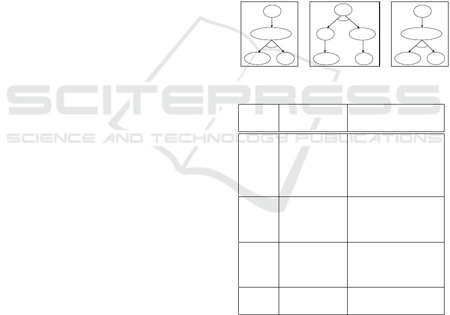
• BG
exp
= {g
0
, g
1
, g
2
} is the set of behavior graphs
representing the possible configurations as pre-
sented in Figure 6.
• R
exp
= {r
1
, r
2
, r
3
, r
4
} are four reconfiguration func-
tions that reconfigure the system from g
0
to g
1
,
from g
1
to g
2
, from g
2
to g
1
, and from g
2
to g
0
,
respectively. These reconfiguration functions are
described in Table 2.
0.5
A
3
A
1
, A
2
A
4
A
5
A
6
, A
7
V
1
V
3
V
2
V
4
V
0
AND
g
1
0.5
A
3
A
1
, A
2
, A
8
A
4
A
6
, A
7
V
1
V
4
V
3
OR
0.7
0.3
1
g
2
V
0
A
0
A
1
, A
2
, A
8
A
4
A
6
, A
7
V
1
V
4
V
3
AND
0.5
0.5
1
g
0
V
0
Figure 6: System configurations.
Table 2: Reconfiguration functions of EXP.
reconfig.
func-
tions
Cond m
r
1
Malfunction 1 new(v
2
)u new(v
0
, 0.5,
v
2
)u mdf(v
0
, 0.5, v
1
)u
new(v
2
, v
4
)u rmv(v
1
,
v
4
)u mdf(v
1
, 1, v
3
)u
rmv(A
8
, v
1
)u AND(v
1
,
v
2
)u rmv(A
0
, v
0
)u
new(A
3
, v
0
)
r
2
User requirement
1: deactivate the
component v
2
rmv(v
2
)u rmv(v
0
, v
2
)u
rmv(v
2
, v
4
)u mdf(v
0
,
1, v
1
)u new(v
1
, 0.7,
v
4
)u mdf(v
1
, 0.3, v
3
)u
new(A
8
, v
1
)u OR(v
3
, v
4
)
r
3
User requirement
2: reactivate the
component v
2
new(v
2
)u new(v
0
, 0.5,
v
2
)u mdf(v
0
, 0.5, v
1
)u
new(v
2
, v
4
)u rmv(v
1
,
v
4
)u mdf(v
1
, 1, v
3
)u
rmv(A
8
, v
1
)u AND(v
1
, v
2
)
r
4
Malfunction 2 rmv(A
3
, v
0
)u new(A
0
, v
0
)
u AND(v
3
, v
4
)u mdf(v
1
,
0.5, v
3
)u mdf(v
1
, 0.5, v
4
)
4.1.1 Structure Repair of EXP
We choose the configuration g
1
of the modeled sys-
tem EXP to apply the structure repair process, the
structure of other configurations is repaired in the
same way. First, g
1
is divided into three blocks. Sec-
ond, a set of mutants is generated according to feasi-
ble mutation operations for each block. Third, SUV
ENASE 2020 - 15th International Conference on Evaluation of Novel Approaches to Software Engineering
402

is queried for acceptance of each mutant to decide fi-
nally about correctness or reparation of the concerned
block. We illustrate in Figure 7 each block with its
generated mutants. One block is repaired through ap-
plying changes of accepted mutants. Repaired blocks
are recomposed to form the repaired structure of the
configuration g
1
.
V
1
V
2
V
0
AND
Block 1
V
1
V
2
V
0
mutant 1
OR
V
1
V
3
V
4
V
2
Block 2
Block 3
Change label
mutant 1
mutant 2
mutant 1
mutant 2
V
2
V
3
V
1
V
4
V
1
V
4
V
2
V
3
Change source
Change source
Change target
Change target
Figure 7: Mutants of the blocks.
4.1.2 Basic Components Repair of EXP
As the purpose is the reparation of basic components,
we only focus on one node (vertex) of one configu-
ration to show the application of this repair process.
Let us consider v
1
of the initial configuration g
0
as
the node which represents the train control (i.e., con-
trols access to a bridge for several trains). We show
in Figure 8, Figure 9, and Figure 10 TA models im-
plementing v
1
. The basic components constituting TA
network represented in v
1
are T 1, T 2, T 3, B, and Q
such that T 1, T 2, and T 3 are three TA models instan-
tiated from the train model, B is one TA model instan-
tiated from the bridge model, and Q is one TA model
instantiated from the queue model.
We suppose that φ = AFG not deadlock is the required
deadlock-free property to be checked (i.e., φ is spec-
ified in CTL). The model-checker used in this exper-
iment is UPPAAL (Bengtsson and Yi, 2003). UP-
PAAL takes the TA network T S(v
1
) and the property
φ as inputs for verification. We show in Figure 11
and Figure 12 verification results and generated coun-
terexample, respectively.
The counterexample shows that the system can not
proceed from any train (i.e., all trains are blocked).
The system is blocked in the state (l
x
, u
x
) = ({start,
occupied, safe, safe, danger}, {time= 186.624113,
time = 980.165337, time = 395.092529}). The clock
”time” is only appeared in the train model, thereby it
is the model that can be incorrectly designed. We have
TA
test
= (T 1, T 2, T 3)), it is sufficient to apply the re-
pair process on one train model because they have the
Figure 8: The train.
Figure 9: The bridge.
Figure 10: The queue.
same design. Mutants that can be generated for the
train model are obtained by:
• negating the guards which gives a mutant m
1
with
time > 10 and a mutant m
2
with time ≤ 7,
• changing guards which gives four mutants m
3
, m
4
,
m
5
, and m
6
with time ≥ 10, time < 10, time ≥ 7,
and time < 7, respectively.
• There are no invariants in this model, relevant mu-
tation operations can not be applied.
• There are no clocks other than time, the change
reset clock operation can not be applied.
Conformance checking is then applied to the six gen-
erated mutants. Results show that m
1
and m
3
are con-
formed mutants. Finally, the process selects m
1
to be
the repaired train model because we suppose that the
designer only forgot to negate the guard on the clock
time. Repaired train model is shown in Figure 13.
To show the performance of our repair approach, UP-
PAAL model-checker is re-applied to T S(v
1
). Figure
14 shows that the property φ is satisfied after repairing
each of T 1, T 2, and T 3.
A Novel Approach for Repairing Reconfigurable Hierarchical Timed Automata
403

Figure 11: Verification result.
Figure 12: Generated counterexample.
Figure 13: Repaired train model.
4.1.3 Inter-repair of EXP
Considering the system EXP, the reconfiguration au-
tomaton of EXP is represented in Figure 15. We
suppose that (g
0
, g
1
, g
2
, g
0
) is the counterexam-
ple generated by the model-checker after EXP inter-
verification, thereby the reconfiguration functions that
can be wrong are r
1
, r
2
, and r
4
. The modeler re-
specifies not accepted reconfiguration functions by
SUV based on structure faults that have been detected
and repaired in the structure repairing phase.
Figure 14: Verification result after reparation.
g
0
g
1
g
2
r
1
r
2
r
3
r
4
Figure 15: Reconfiguration automaton of EXP.
4.2 Evaluation of Performance
4.2.1 Evaluation in Term of Number of
Repaired Faults
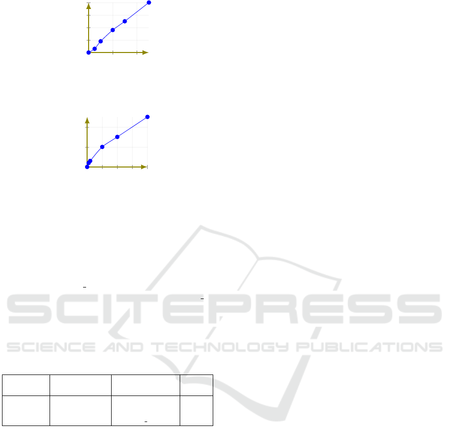
The number of repaired faults is dependant on the
number of incorrect clocks constraints and the com-
munication between these clocks in a TA network.
The generated counterexample is able to detect and
cover wrong guards, resets, and invariants in TA mod-
els as much as they are connected. The curve in Fig-
ure 16 shows that the approach is able to repair a
considerable number of detected incorrect clock con-
straints. On the other hand, the number of repaired
structural faults is dependant on the size of RHTA.
Indeed, the number of structural faults is developed
slowly comparing to RHTA size because the designer
makes fewer faults during structure modeling. Figure
17 shows that the number of repaired structural faults
is correspondent to this development.
4.2.2 Evaluation in Term of Reparation Time
The proposed approach has a reasonable complexity
compared to the large size of RHTA models. We show
in Table 3 the required time for each repairing phase
where: 1) 2O(3p) is the complexity of applying the
three mutation operations over p blocks and apply-
ing acceptance testing on all generated mutants. 2)
ENASE 2020 - 15th International Conference on Evaluation of Novel Approaches to Software Engineering
404
0 20 40
0
10
20
30
40
Incorrect clock constraints
Repaired faults
Figure 16: Evaluation of the number of repaired clock con-
straints.
0
50
100
150
200
0
10
20
Number of nodes (vertices)
Repaired structural faults
Figure 17: Evaluation of the number of repaired structural
faults.
O(|BC|) is the complexity of extracting incorrect ba-
sic components, 2O(5|TA
test
|) is the complexity of
applying and testing all mutants generated after ap-
plying the five mutation operations on each TA of
TA
test
, and O(accpt mt) is the complexity of select-
ing a repaired TA from accepted mutants (accpt mt
is the number of accepted mutants). 3) 2O (r) is the
complexity of testing and repairing r reconfiguration
functions which are appeared in the generated coun-
terexample.
Table 3: Required correction time for each phase.
Phase Structure repair clock constraints
repair
inter-
repair
Complexity 2O(3p) O(|BC|) +
2O(5|TA
test
|) +
O(accpt mt)
2O(r)
5 CONCLUSION
This paper proposes an approach of three phases for
repairing RHTA models, (i) structure repair, (ii) ba-
sic components repair, and (iii) inter-repair. The ap-
proach is based on mutation testing and the generated
counterexample from the RHTA verification stage.
One counterexample is not able to detect all faults
in one configuration however, it covers many parts
that can be wrong. The paper also provides an appli-
cation example on a simple reconfigurable hierarchi-
cal system designed with RHTA for illustrating both
of structure repair process and inter-repairing of an
RHTA. For applying and evaluating the basic compo-
nents repair process, the train gate system is used as
a real timed system. The process is able to detect and
repair incorrect guards in basic components (TA mod-
els) which makes the model satisfying the required
property.
In future work, we plan to add improvements to
the proposed approach in order to control the cost of
time and memory space required for repairing large
RHTA such as RHTA modeling smart grids as hierar-
chical reconfigurable systems.
REFERENCES
Aichernig, B. K., H
¨
ormaier, K., and Lorber, F. (2014). De-
bugging with timed automata mutations. In Inter-
national Conference on Computer Safety, Reliability,
and Security, pages 49–64. Springer.
Aichernig, B. K., J
¨
obstl, E., and Tiran, S. (2015). Model-
based mutation testing via symbolic refinement check-
ing. Science of Computer Programming, 97:383–404.
Aichernig, B. K., Lorber, F., and Ni
ˇ
ckovi
´
c, D. (2013).
Time for mutants—model-based mutation testing with
timed automata. In International Conference on Tests
and Proofs, pages 20–38. Springer.
Andr
´
e,
´
E., Arcaini, P., Gargantini, A., and Radavelli,
M. (2019). Repairing timed automata clock guards
through abstraction and testing. In International Con-
ference on Tests and Proofs, pages 129–146. Springer.
Arcaini, P., Gargantini, A., and Radavelli, M. (2019).
Achieving change requirements of feature models by
an evolutionary approach. Journal of Systems and
Software, 150:64–76.
Bengtsson, J. and Yi, W. (2003). Timed automata: Seman-
tics, algorithms and tools. In Advanced Course on
Petri Nets, pages 87–124. Springer.
Bettira, R., Kahloul, L., Khalgui, M., and Li, Z. (2019).
Reconfigurable hierarchical timed automata: Model-
ing and stochastic verification. In 2019 IEEE Interna-
tional Conference on Systems, Man and Cybernetics
(SMC), pages 2364–2371. IEEE.
Boucheneb, H., Gardey, G., and Roux, O. H. (2009). Tctl
model checking of time petri nets. Journal of Logic
and Computation, 19(6):1509–1540.
Bouyer, P. et al. (2008). Model checking timed automata.
Hessel, A., Larsen, K. G., Mikucionis, M., Nielsen, B., Pet-
tersson, P., and Skou, A. (2008). Testing real-time
systems using uppaal. In Formal methods and testing,
pages 77–117. Springer.
Krichen, M. and Tripakis, S. (2009). Conformance testing
for real-time systems. Formal Methods in System De-
sign, 34(3):238–304.
Luthmann, L., Gerecht, T., Stephan, A., B
¨
urdek, J., and
Lochau, M. (2019). Minimum/maximum delay test-
ing of product lines with unbounded parametric real-
time constraints. Journal of Systems and Software,
149:535–553.
Nielsen, B. and Skou, A. (2003). Automated test genera-
tion from timed automata. International Journal on
Software Tools for Technology Transfer, 5(1):59–77.
A Novel Approach for Repairing Reconfigurable Hierarchical Timed Automata
405

Roufaida, B., Laid, K., and Mohamed, K. (2019). Parallel
verification methodology of reconfigurable hierarchi-
cal timed automata. In The 2019 European Simulation
and modeling Conference. eti.
Schmaltz, J. and Tretmans, J. (2008). On conformance test-
ing for timed systems. In International Conference
on Formal Modeling and Analysis of Timed Systems,
pages 250–264. Springer.
Springintveld, J., Vaandrager, F., and D’Argenio, P. R.
(2001). Testing timed automata. Theoretical computer
science, 254(1-2):225–257.
ENASE 2020 - 15th International Conference on Evaluation of Novel Approaches to Software Engineering
406
