
Systematic Treatment of Security Risks during Requirements
Engineering
Roman Wirtz and Maritta Heisel
Working Group Software Engineering, University of Duisburg - Essen, Oststr. 99, Duisburg, Germany
Keywords:
Security Risk, Risk Management, Risk Treatment, Controls, Requirements Engineering, Model-based,
Patterns.
Abstract:
In recent years, a significant number of security breaches have been reported. A security breach can lead
to value loss for stakeholders, not only financially but also in terms of reputation loss. The likelihood and
consequnce of a scenario, impacting security of software, constitute a risk level. Risk management describes
coordinated activities to identify, evaluate, and treat risks. Following the principle of security-by-design and
treating risks as early as possible during software development, the costs can be reduced significantly. Based
on our previous work to identify and evaluate risks, we aim to assist developers in treating risks in one of the
earliest phases, i.e. during requirements engineering. To do so, we propose a stepwise method that allows
selecting and documenting suitable countermeasures, i.e. controls. As input, it takes a requirements model
and a CORAS security model. A distinguishing feature of our method is that we use patterns in the form of
templates to evaluate the effectiveness of controls. Furthermore, we integrate the selected controls into the
requirements model following an aspect-oriented approach. The resulting model can be used as input for the
design phase, thus helping to create an architecture that considers security right from the beginning.
1 INTRODUCTION
Incident scenarios in which the security of software
is harmed have become more and more frequent in
the recent years (BSI, 2019b). Each of those inci-
dents may cause value and reputation loss for stake-
holders, e.g. for companies dealing with sensitive
data (Kaspersky Lab, 2019). The likelihood of such
a scenario and its consequence for an asset is called
risk. The ISO 27005 standard (ISO, 2018) provides
guidelines to deal with such risks. The standard con-
tains a risk management process describing coordi-
nated activities to identify incident scenarios, evalu-
ate their likelihoods and consequences, and finally to
treat the identified risks. To treat a risk means identi-
fying countermeasures that reduce that risk to a pre-
defined acceptable level. Countermeasures, i.e. con-
trols, can either be implemented by software, e.g. an
encryption mechanism, or can be embedded in the en-
vironment, e.g. access control to a data center. The
later one considers security for software under devel-
opment, the higher are the costs to treat risks. There-
fore, developers should identify and treat risks in the
earliest stages of a software development lifecycle,
following the principle of security-by-design (Hask-
ins et al., 2004).
In previous work, we have developed methods to
identify and evaluate risks based on the functional
requirements of the software to be developed. We
provided a template to describe incident scenarios
that harm the security of software (Wirtz and Heisel,
2019d). Furthermore, we use that template to evaluate
the risks related to the scenario in a semi-automatic
way (Wirtz and Heisel, 2019b). Our model-based ap-
proach based on Problem Frames (Jackson, 2001) and
CORAS (Lund et al., 2010) ensures consistency be-
tween the requirements model and the security model.
In the present paper, we aim to assist security en-
gineers and software developers in selecting and doc-
umenting appropriate countermeasures. As prelimi-
nary work, we developed a template to describe con-
trols based on a set of attributes. We now propose a
method to select controls reducing the identified risks
to an acceptable level. Our method takes a require-
ments model and a CORAS security model as input.
To evaluate the effectiveness of a control, we make
use of our templates and the Common Vulnerability
Scoring System (CVSS) (FIRST.org, 2015). To bridge
the gap between security and requirements, we finally
integrate the selected controls in the problem frames
132
Wirtz, R. and Heisel, M.
Systematic Treatment of Security Risks during Requirements Engineering.
DOI: 10.5220/0009397001320143
In Proceedings of the 15th International Conference on Evaluation of Novel Approaches to Software Engineering (ENASE 2020), pages 132-143
ISBN: 978-989-758-421-3
Copyright
c
2020 by SCITEPRESS – Science and Technology Publications, Lda. All rights reserved
model following an aspect-oriented approach.
The resulting model can then be used as input for
the design phase, thus helping to create an architec-
ture that takes security into account right from the be-
ginning.
The remainder of the paper is structured as fol-
lows: In Section 2, we briefly describe our relevant
previous work and necessary background. In Sec-
tion 3, we introduce the underlying models, i.e. re-
quirements model and security model. The method,
which is our main contribution, is described in Sec-
tion 4. We discuss our results and provide an evalu-
ation plan in Section 5, followed by related work in
Section 6. Finally, we conclude the paper in Section 7
with a summary and an outlook on future research di-
rections.
2 FUNDAMENTALS
In this section, we introduce the necessary back-
ground and our previous work in the context of risk
management.
2.1 Problem Frames
For modeling requirements, we make use of problem
diagrams which consist of domains, phenomena, and
interfaces (Jackson, 2001). We make use of Google’s
Material Design
1
to illustrate the diagrams in a user-
friendly way (Wirtz and Heisel, 2019c).
Machine domains ( ) represent the piece of soft-
ware to be developed.
Problem domains represent entities of the real
world. There are different types: biddable domains
with an unpredictable behavior, e.g. persons ( ),
causal domains ( ) with a predictable behavior, e.g.
technical equipment, and lexical domains ( ) for data
representation. A domain can take the role of a con-
nection domain ( ), connecting two other domains,
e.g. user interfaces or networks.
Interfaces between domains consist of phenom-
ena. There are symbolic phenomena, representing
some kind of information or a state, and causal phe-
nomena, representing events, actions, and commands.
Each phenomenon is controlled by exactly one do-
main and can be observed by other domains. A phe-
nomenon controlled by one domain and observed by
another is called a shared phenomenon between these
two domains. Interfaces (solid lines) contain sets of
shared phenomena. Such a set contains phenomena
1
Google Material - https://material.io (last access:
February 20, 2020)
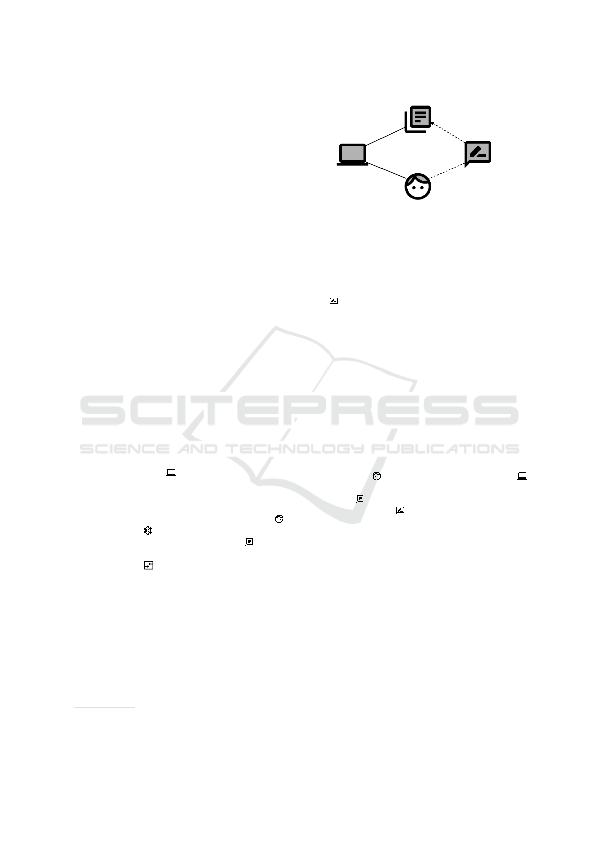
Update
Person
Software
Information
updateInformation
information
P!{provideInformation}
S!{updateInformation}
Figure 1: Example for Problem Diagram.
controlled by one domain indicated by X!{...}, where
X stands for an abbreviation of the name of the con-
trolling domain.
A problem diagram contains a statement in form
of a functional requirement (represented by the sym-
bol ) describing a specific functionality to be de-
veloped. A requirement is an optative statement that
describes how the environment should behave when
the software is installed.
Some phenomena are referred to by a requirement
(dashed line to controlling domain), and at least one
phenomenon is constrained by a requirement (dashed
line with arrowhead and italics). The domains and
their phenomena that are referred to by a requirement
are not influenced by the machine, whereas we build
the machine to influence the constrained domain’s
phenomena in such a way that the requirement is ful-
filled.
In Figure 1, we show a small example describing
a functional requirement for updating some informa-
tion. A Person
provides information to Software
to be updated. We make use of a lexical domain In-
formation to illustrate a database. The functional
requirement Update refers to the phenomenon up-
dateInformation and constrains the phenomenon in-
formation.
2.2 CORAS
CORAS is a model-based method for risk manage-
ment (Lund et al., 2010). It consists of a stepwise
process and different kinds of diagrams to document
the results. Each step provides guidelines for the in-
teraction with the customer on whose behalf the risk
management activities are carried out. The results are
documented in diagrams using the CORAS language.
The method starts with the establishment of the con-
text and ends with the suggestion of treatments to ad-
dress the risk.
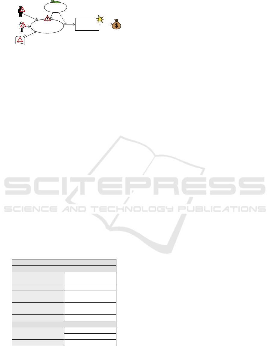
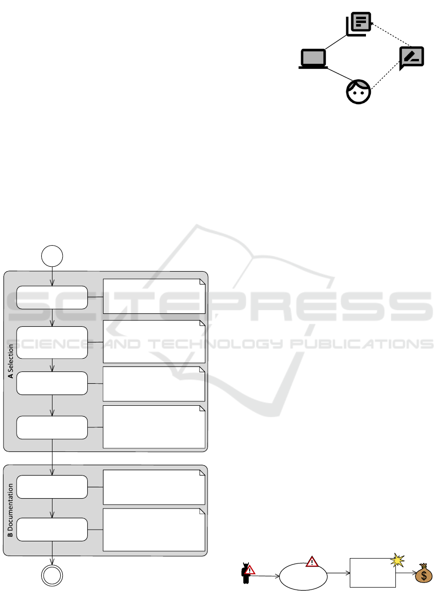
Identified risks can be documented in a so-called
threat diagram for which we show an example in Fig-
ure 2. A threat diagram consists of the following
Systematic Treatment of Security Risks during Requirements Engineering
133
Human
Threat
Deliberate
Non-
Human
Threat
Unwanted
Incident
Unwanted
Incident
Human
Threat
Accidental
Human
Threat
Accidental
Asset
Threat
Scenario
Threat
Scenario
initiates
leads
to
impacts
Treatment
Scenario
Treatment
Scenario
treats
reduces
Figure 2: CORAS Threat Diagram.
elements: An Asset is an item of value. There are
Human-threats deliberate, e.g. a network attacker,
as well as Human-threats accidental, e.g. an em-
ployee pressing a wrong button accidentally. To de-
scribe technical issues there are Non-human threats,
e.g. malfunction of software. A threat initiates a
Threat scenario with a certain likelihood, and a threat
scenario describes a state, which may lead to an un-
wanted incident with another likelihood. An Un-
wanted incident describes the action that actually im-
pacts an asset, i.e. has a negative consequence for it.
In the following, we will use the term incident sce-
nario as given in the ISO 27005 standard (ISO, 2018).
In the context of CORAS, an incident scenario de-
scribes the path between threat and asset and the re-
lated elements, i.e. threat scenario and unwanted in-
cident. It can be further specified using our template
which we describe in Section 2.3.
To describe controls, there are Treatment Sce-
narios. The solid arrow points to the element which
the control treats, e.g. the threat scenario. Addition-
ally, we introduce a dashed arrow that points to the
likelihood or consequence which will be reduced, e.g.
the likelihood that a threat scenario leads to an un-
wanted incident. The template given in Section 2.4
allows describing controls in a systematic way.
Table 1: Description of Database Injection.
Incident Information
LeadsTo Likelihood
Threat Vector Network X Adjacent
Local Physical
Complexity X Low High
Privileges
Required
None X Low High
User
Interaction
X None Required
Threat Scope Unchanged X Changed
Consequences
Confidentiality Impact None Low X High
Integrity Impact X None Low High
Availability Impact X None Low High
2.3 Template for Incident Scenarios
In previous work, we proposed a pattern that de-
scribes an incident scenario based on the base met-
rics of the CVSS (Wirtz and Heisel, 2019d). Table 1
shows the relevant excerpt of a pattern instance for the
scenario Database Injection. In the following, we ex-
plain the different metrics and corresponding values.
For each attribute, we state its relation to the different
elements and relations of the CORAS language.
The first set of attributes can be used to specify the
likelihood that a threat scenario leads to an unwanted
incident.
The Threat Vector (attack vector in CVSS) de-
scribes possible ways how to realize a threat scenario.
There are four different values: (1) network, which
means access from an external network; (2) adjacent,
which means a local network; (3) local, which means
direct access to the computer; and (4) physical, which
describes access to the hardware.
The Complexity of a scenario is defined by two
possible values: low and high. A high effort is re-
quired when a threat needs some preparation to real-
ize the threat scenario and that the scenario cannot be
repeated an arbitrary number of times.
To state whether privileges are required to suc-
cessfully realize the threat scenario, we make use of
the corresponding attribute. There are three possible
values: (1) None; (2) Low, e.g. a user account; and
(3) High, administrative rights.
A realization may require some User Interaction,
for example by confirming the installation of mali-
cious software.
The Threat Scope denotes the range of a scenario.
A changed scope means that the part being attacked
is used to reach other parts of software. For example,
an attacker uses the wireless connection to access the
database.
The impact on confidentiality, integrity, and avail-
ability is measured using qualitative scales. The used
scale consists of three values: None, Low and High.
In the context of CORAS, the value states the conse-
quences that unwanted incidents have for an asset.
In previous work, we developed a method that al-
lows evaluating risks using the CVSS metrics (Wirtz
and Heisel, 2019b). We will use the calculated sever-
ities to determine the effectiveness of controls.
2.4 Template for Controls
We further provide a pattern that allows to describe
controls in the same manner as incident scenarios
(Wirtz and Heisel, 2019a). In Table 2, we provide an
ENASE 2020 - 15th International Conference on Evaluation of Novel Approaches to Software Engineering
134
Table 2: Description for Encrypted Storage.
Context
Description The control can be applied for soft-
ware where data shall be stored per-
sistently.
Functional Requirement The problem diagram is given in Fig-
ure 3(a).
Benefits
Reduction of leadsTo likelihood
Modified Complexity Not defined Low X High
Modified Privileges Re-
quired
X Not defined None Low
High
Modified User Interaction X Not defined None Required
Modified Threat Scope X Not defined Unchanged
Changed
Reduction of consequences
Modified Confidentiality
Impact
Not defined None X Low
High
Modified Integrity Impact X Not defined None Low
High
Modified Availability Im-
pact
X Not defined None Low
High
Reduction of initiates likelihood
Hints The likelihood for initiating the threat
scenario cannot be reduced.
Liabilities
Costs Since there are many open source li-
braries that can be used to implement
the control, the costs do not increase
significantly.
Usability There is no impact on the usability.
Performance Depending on the size of data, the per-
formance may decrease. The higher
the size of data, the lower the perfor-
mance.
Integration
Aspect diagram The aspect diagram is given in Fig-
ure 3(b).
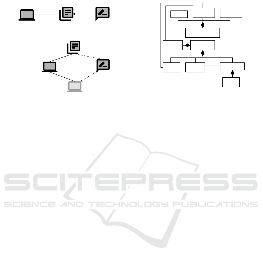
example for the control Encrypted Storage. It allows
encrypting data before storing them persistently.
First, we informally describe the context in which
a control can be applied. Furthermore, we state the
functional requirement in the form of a problem di-
agram for which the control is suitable. Figure 3(a)
shows the corresponding diagram for the example.
For applying the control, it is necessary that a Storage
Machine stores data persistently in a Database .
The corresponding requirement constrains the lexical
domain.
Furthermore, we distinguish between the benefits
and liabilities of a control, and we provide an aspect-
oriented integration into the requirements model.
Benefits. For specifying the benefits, we use a set of
attributes according to the CVSS specifications, e.g.
Modified Complexity. Each attribute is a counterpart
for the attribute used in the incident description. Mod-
ified means that the complexity of the incident has the
new value after applying the control. For example, the
complexity is high after applying the control, because
the data need to be decrypted for disclosure. The
range of values for each attribute is the same as for
the attributes of the incident description. Addition-
ally, there is the value not defined which means that
the control does not influence that specific attribute,
i.e. the value specified by the incident description will
stay the same after applying the control.
The leadsTo likelihood can be reduced by increas-
ing the complexity, by requiring higher privileges, by
requiring a user interaction, or by modifying the threat
scope. The consequences can be reduced separately
for confidentiality, integrity, and availability. In Sec-
tion 4.6, we use the values to evaluate the effective-
ness of a control concerning incidents to be treated.
The CVSS specification does not provide at-
tributes to specify the likelihood that a threat initi-
ates a threat scenario. Therefore, we provide a textual
description of how a control affects that likelihood.
These are given as hints in the last section of the spec-
ification of benefits.
Liabilities. We distinguish between costs, usability,
and performance. In Section 4.5, we use the hints
together with the context description to validate the
applicability of a control for a concrete software de-
velopment project.
Integration. To integrate controls into the require-
ments model, we make use of an aspect-oriented ap-
proach that has been proposed by Faßbender et al.
(Faßbender et al., 2014). For each control, we pro-
vide an aspect diagram which has a similar notation as
problem diagrams. In addition to problem domains,
there are placeholders called joint-points (marked in
light gray). Problem domains of an aspect diagram
will be added to the requirements model, whereas a
placeholder will be instantiated with an existing do-
main. For the Encrypted Storage, we provide an as-
pect diagram in Figure 3(b). Encryption Machine
and Key Storage are problem domains, Machine
is a joint-point. The requirement for encryption refers
to the key and constrains the encrypted data. In Sec-
tion 4.8, we describe the integration of controls into
the requirements model in more detail.
3 UNDERLYING MODELS
For our method, we consider two different models: (i)
Requirements model and (ii) Security model. To en-
Systematic Treatment of Security Risks during Requirements Engineering
135
Storage
Database
Storage Machine
data
SM!{storeData}
(a) Functional Requirement
Key Storage
Encryption
Machine
Encryption Machine
key
KS!{key}
M!{encrypt}
EM!{returnData}
encryptedData
(b) Aspect Diagram
Figure 3: Diagrams for Symmetric Encryption.
sure consistency, we provide references between the
models. In Figure 4, we provide an overview of both
models and their relations. Note, that we do not show
each element explicitly. We focus on the relevant as-
pects for our method. In the following, we briefly
describe them.
3.1 Requirements Model
To model requirements, we make use of Jackson’s
problem frames as described in Section 2.1. The ini-
tial requirements model is the input for our method
and covers all functional requirements of the software
under development. In the last step of our method,
we add selected controls to the requirements model.
Therefore, there is a reference between treatment sce-
narios of the security model and the corresponding
functional requirements. Problem diagrams can be
used to structure a requirements model. They con-
tain all domains and interfaces that are relevant for a
specific requirement.
3.2 Security Model
Our security model is based on CORAS. Therefore,
it contains the identified risks using the CORAS ele-
ments as described in Section 2.2. Besides, it contains
the security goals in the form of a piece of information
that shall be protected concerning confidentiality, in-
tegrity, or availability. In the requirements model, we
model a piece of information with a symbolic phe-
nomenon. Therefore, the security goal holds a ref-
erence to the corresponding phenomenon. A threat
diagram focusses on a specific incident scenario, i.e.
it shows the corresponding elements contained in the
model. To further specify such scenarios, we make
Treatment
Scenario
*
Threat
Scenario
*
Unwanted
Incident
1
Security
Property
*
Security Goal
*
*
*
Symbolic
Phenomenon
Domain
Functional
Requirement
Security Model
(CORAS)
Requirements Model
(Problem Frames)
1
*
1
*
impacts
1
*
Figure 4: Models overview.
use of our template as described in Section 2.3. A
threat scenario holds a reference to the functional re-
quirement in which context it may be initiated. A se-
curity model is a required input for our method. Us-
ing treatment scenarios, we model selected controls
which can be specified with our template (cf. Sec-
tion 2.4). For controls that can be implemented as ad-
ditional software functionality, the treatment scenario
holds a reference to the added functional requirement.
4 CONTROL SELECTION &
EVALUATION
Figure 5 provides an overview of the structure of the
method, which consists of six steps. The six steps
can be divided into two phases. The first four steps
deal with the selection of an appropriate control, and
the other two steps deal with its documentation. Our
method is iterative, which means that we carry out the
steps for all unacceptable risks, i.e. identified incident
scenarios to be treated. In the following, we describe
the different steps in detail. For all steps, we implic-
itly consider the set of available control descriptions
as input.
4.1 Initial Input
To carry out our method, we require the following ini-
tial input:
1. Requirements Model: To decide about the ap-
plicability of controls, we require a requirements
model as input. That model shall be based on
Jackson’s problem frames approach (cf. Sec-
tion 2.1. We will later integrate the controls into
that model.
2. CORAS Security Model: In previous steps of
the risk management process, we identified in-
ENASE 2020 - 15th International Conference on Evaluation of Novel Approaches to Software Engineering
136
cidents that might lead to harm for at least one
asset. Those incidents have been documented in
CORAS threat diagrams. Besides, we require the
corresponding template description as described
in Section 2.3.
3. Catalogue of Controls: Controls that shall be
considered for our selection process have to be
specified with the template we described in Sec-
tion 2.4
4.2 Running Example
To illustrate the application of our method, we make
use of a smart grid scenario. A smart grid is an in-
telligent power supply network, which also allows
measuring a customer’s power consumption remotely.
Since such networks are critical infrastructures, they
are often subject to attacks, and due to their complex-
ity, it is hard to analyze their security (Kumar et al.,
2019; Tellbach and Li, 2018).
1. Consider security
property
2. Consider
functional
requirement
4. Evaluate
effectiveness
3. Validation of
context and liabilities
5. Document
treatment scenario
6. Extend
requirements model
Input: Unwanted incident
Output: Subset of possibly
suitable controls
Input: Incident description;
Problem diagram
Output: Subset of possibly
suitable controls
Input: Incident description;
Threat diagram; Risk matrix
Output: Control(s) to be
applied
Input: Domain knowledge
Output: Subset of possibly
suitable controls
Input: CORAS security model
Output: Extended CORAS
security model
Input: Requirements model;
Aspect diagram
Output: Extended
requirements model
Figure 5: Method overview.
FR: Store PD
Customer
Configuration
Communication Hub
personalData
enterData
C!{enterData}
CH!{storePD}
Figure 6: Example: Problem diagram for storing personal
data.
Requirements Model. The software to be devel-
oped is the Communication Hub, which serves as the
gateway between a customer’s home and the energy
supplier. In this paper, we focus on the functional re-
quirement for storing personal data of a customer. We
show the corresponding problem diagram in Figure 6.
A customer can store his/her personal data in the com-
munication hub’s internal database.
CORAS Security Model. The personal data shall
be protected regarding confidentiality. We show the
simplified CORAS threat diagram in Figure 7, which
is part of the security model. An attacker may in-
ject malicious database queries via the customer’s in-
terface to disclose personal data. In this scenario,
the command to store the personal data (FR:Store
PD) will be replaced with a query. In Table 1, we
presented the corresponding template instance that
describes the incident scenario represented by the
CORAS diagram.
Catalogue of Controls. In Table 2, we presented
the template instance for the control Encrypted Stor-
age. We will use this instance to exemplify our
method.
In the following, we apply the steps of the method
for this example.
4.3 Step 1: Consider Security Property
To decide whether a control is suitable, we first com-
pare the violated security property with the properties
that can be improved with the control.
Attacker
Harm
confidentiality
of personal
data
Harm
confidentiality
of personal
data
personal
data
Inject malicious
query
Inject malicious
query
Figure 7: Example: Identified risks.
Systematic Treatment of Security Risks during Requirements Engineering
137

Description. For the first step, we consider the un-
wanted incident of the incident scenario under investi-
gation. It denotes the security property that is harmed.
We search a control that helps to preserve that prop-
erty, which is indicated by its modified impact metric
(cf. Section 2.3). We, therefore, consider those con-
trols for further investigation that address the security
property stated in the unwanted incident.
The first step can be automated since the required
information can be stored and evaluated based on the
underlying security model and template instances.
Example. The unwanted incident given in Fig-
ure 7 states the harm of confidentiality. The control
Encrypted Storage helps to improve confidentiality.
Therefore, we consider the control as relevant.
4.4 Step 2: Consider Functional
Requirement
Second, we compare the functional requirement given
in the incident description with the corresponding
problem diagram.
Description. As mentioned in Section 3, a threat
scenario references the functional requirement in
which context it occurs. Not all controls can be ap-
plied to all functional requirements, e.g. controls for
data transmission vs. controls for data storage. In
the present step, we select those controls that are ap-
plicable to the functional requirement related to the
threat scenario. To do so, we inspect the correspond-
ing problem diagram of the requirements model. We
consider a control as possibly relevant when the prob-
lem diagram contains the domains, domain interfaces,
and requirement references (constrains and refers to)
given in the control description. Note, that a problem
diagram may contain additional elements in contrast
to the control description. The description only con-
tains a minimal set of elements.
By implementing a method for pattern matching,
this step can be automated based on the information
available in the models.
Example. The control description (cf. Figure 3(a))
states a problem diagram containing a Storage Ma-
chine
and a Database. The requirement constrains
the lexical domain. The machine and the lexical do-
main are connected via a domain interface. The anno-
tated phenomenon is controlled by the machine. The
problem diagram from our scenario given in Figure 6
contains those elements. Therefore, the control is ap-
plicable in the context of the requirement.
4.5 Step 3: Validation of Context and
Liabilities
In the third step, we validate the context and liabilities
of controls to decide about their applicability.
Description. This step requires the interaction with
domain experts, for example, the software provider.
Such an expert provides further necessary domain
knowledge. The control description template states
details about the context, as well as details about lia-
bilities, i.e. costs, usability, and performance. Those
attributes have to be compared with the environment
in which the software under development will later be
integrated. For example, software running on small
servers does not provide much computational power
for strong encryption mechanisms. Furthermore, it
is necessary to consider the costs for implementing
a control compared to the asset value to be protected.
Since the context and liabilities are given in nat-
ural language and the requirements model does not
capture all attributes of the environment, this step re-
quires manual interaction.
Example. Considering the control description
given in Table 2, we decide to choose the control
Encrypted Storage for treating the incident scenario.
There are no liabilities concerning costs and usability.
Since a customer only stores his/her personal data
which has a small data size, there is no major impact
on the performance.
4.6 Step 4: Evaluate Effectiveness
In the fourth step, we evaluate the effectiveness of
the filtered controls. The effectiveness helps to finally
choose the controls to be applied.
Description. To evaluate the effectiveness of a con-
trol, we make use of its description and the risk ma-
trix which has been defined during risk evaluation. In
previous work, we provide a method to evaluate risks
using the CVSS (Wirtz and Heisel, 2019b). The first
dimension of the risk matrix is the frequency per year
that a threat initiates a threat scenario (cf. y-axis of
Table 3). The second dimension is the severity of an
incident scenario (cf. x-axis of Table 3). The sever-
ity is defined by the likelihood that a threat scenario
leads to an unwanted incident and the consequence
for an asset. The qualitative scale for the severity is
defined by the CVSS (FIRST.org, 2015). To calcu-
late the severity, we make use of the incident scenario
description which contains the attributes defined by
ENASE 2020 - 15th International Conference on Evaluation of Novel Approaches to Software Engineering
138
the CVSS specification. The CVSS provides a calcu-
lator
2
to calculate the severity. The calculator takes
all attributes as input which are given in the incident
scenario description (cf. Section 2.3).
To evaluate the effectiveness of a control, we use
the modified metrics given in the control description.
The CVSS calculator allows us to enter the modified
values and to calculate the new severity. In case that
the control reduces the frequency that a threat initiates
a threat scenario, the new frequency has to be defined
manually. The control description provides hints for
that task.
Next, we use the risk matrix to evaluate effective-
ness. If the combination of new frequency and new
severity leads to acceptable risk, indicated by a green
cell, we consider the control as applicable. Some-
times, a single control does not lead to a sufficient risk
reduction, thus making it necessary to consider com-
binations of controls. For example, the first control
reduces the severity, whereas the second one reduces
the frequency. In that case, we combine the risk re-
duction of the controls and evaluate the corresponding
reduction with the risk matrix.
The result of the effectiveness evaluation is a set of
controls and control combinations that lead to a suf-
ficient risk reduction. Finally, it is necessary to se-
lect the controls that shall be implemented. Different
criteria can be used for that task, e.g. the maximum
reduction or the costs for implementation. If there is
no control or combination of controls to reduce the
risk sufficiently, the two steps of documentation can
be skipped for that incident scenario. However, it is
still necessary to document that a sufficient reduction
is not possible for further discussion.
The calculation of the severity can be automated
based on the control and incident description and the
CVSS calculator. The frequency needs to be adjusted
manually. Therefore, the step can be semi-automated.
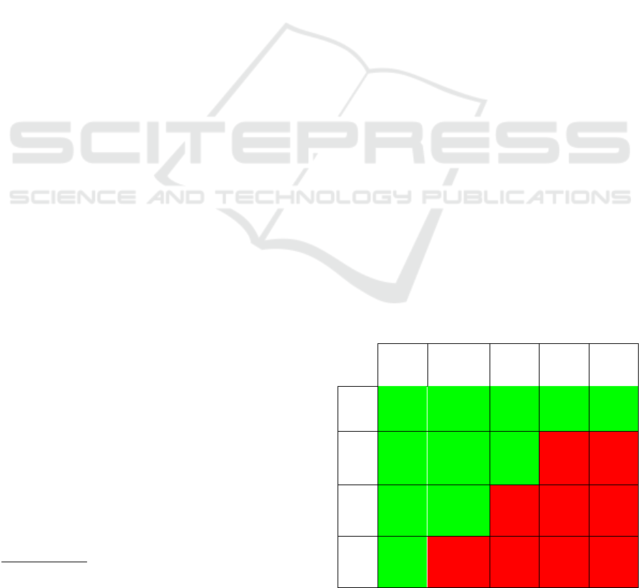
Example. In Table 3, we show the risk matrix we
consider for the evaluation. We use Inject. as an ab-
breviation for the risk that an attacker injects mali-
cious database queries.
During risk evaluation, a frequency of 40 times
per year (frequently) that the attacker injects mali-
cious database queries has been estimated. The at-
tributes’ values given in Table 1 lead to a severity of
6.8 (medium). The corresponding red cell in the risk
matrix indicates an unacceptable risk.
The control description is given in Table 2 and
does not state any reduction of the frequency. Next,
we consider the modified values for complexity and
2
CVSS Calculator - https://www.first.org/cvss/
calculator/3.0 (last access: 29 December 2019).
confidentiality impact which we enter in the CVSS
calculator together with the values contained in the
incident description. The new severity is 3.0 (low)
which we enter to the risk matrix. The risk after ap-
plying the control (Inject.
treat
) is acceptable. There-
fore, the effectiveness of the control is sufficient, and
the control will be further considered.
4.7 Step 5: Document Treatment
Scenario
After a suitable control has been selected, we docu-
ment the corresponding treatment scenario in the se-
curity model using the CORAS language.
Description. To document the selected control, we
make use of a treatment scenario (cf. Section 2.2).
The solid arrow indicates which threat scenario the
control treats. Furthermore, we add dashed arrows to
indicate a likelihood or consequence reduction. Those
arrows can have an initiates, leadsTo, or impacts rela-
tion as target. The control description denotes which
likelihoods or consequences can be reduced, and the
arrows have to be added accordingly.
Currently, there are no formal rules on how the
treatment scenario has to be created. Therefore, it is
necessary to extend the diagram manually. Using a
model-based editor, all information can be stored in
the same model to ensure consistency.
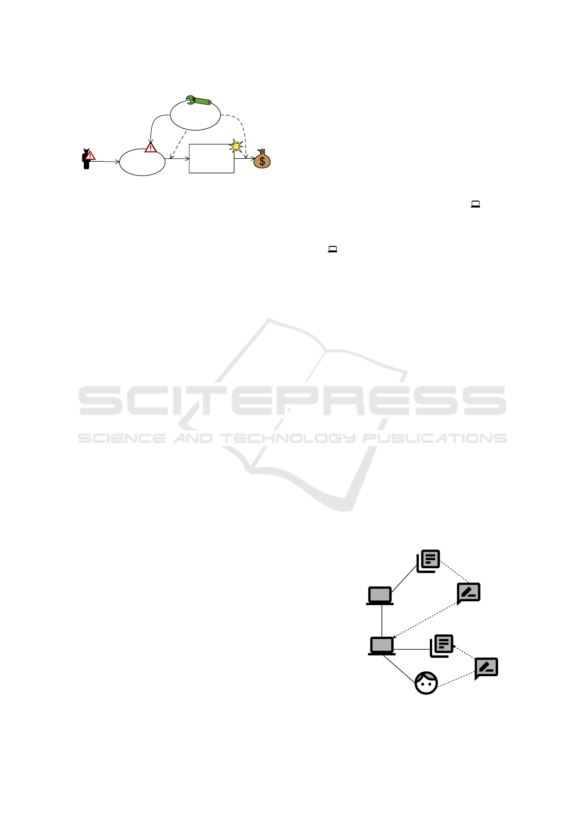
Example. We add the treatment scenario Encrypt
personal data to the initial threat diagram (cf. Fig-
ure 8). The control treats the threat scenario which
is related to the functional requirement for storing
the personal data. The control description given in
Table 3: Example: Risk matrix.
None
0.0
Low
0.1–3.9
Medium
4.0–6.9
High
7.0–8.9
Critical
9.0–
10.0
Never
0 times
Seldom
≤ 20 times
Frequently
≤ 50 times
Inject.
treat
Inject.
Often
> 50 times
Systematic Treatment of Security Risks during Requirements Engineering
139
Attacker
Harm
confidentiality
of personal
data
Harm
confidentiality
of personal
data
personal
data
Inject malicious
query
Inject malicious
query
Encrypt personal
data
Encrypt personal
data
confidentialityImpact
=low
complexity=
high
Figure 8: Example: Extended CORAS threat diagram.
Table 2 states a modified complexity and a modi-
fied confidentiality impact. Therefore, there are two
dashed arrows. The first one points to the leadsTo re-
lation describing the corresponding likelihood reduc-
tion. The second one points to the impacts relation
which indicates the reduction of consequences. Fig-
ure 8 shows the resulting diagram.
4.8 Step 6: Extend Requirements Model
The final step of our method integrates the functional
requirements for selected controls in the requirements
model.
Description. The last step needs to be carried out
for those controls that are realized as additional soft-
ware functionalities, e.g. encryption mechanisms.
To integrate controls into the requirements model,
we follow an aspect-oriented approach for problem
frames (Faßbender et al., 2014). As input for this step,
we consider the problem diagram related to the threat
scenario and the aspect diagram given in the control
description.
We add the control to the problem diagram in
the following way: The aspect diagram contains do-
mains, joint-points and the functional requirement for
the control. We add the domains to the problem dia-
gram along with the corresponding domain interfaces.
Since a joint-point represents a placeholder for a do-
main of the problem diagram, we instantiate it accord-
ingly. Furthermore, we add the functional require-
ment for the control and the requirement references.
The resulting requirements model can be used in
the following design phase. An architecture that can
be created based on that model considers security
right from the beginning.
Controls that influence the environment, e.g. se-
curity training for employees, will not be considered
in this step. We document those controls only in the
CORAS security model since they do not need to be
considered for software design decisions.
There are existing tools that support aspect-
oriented requirements engineering. When using such
tools with our models, the step can at least be semi-
automated. Some adjustments, e.g. the naming of
domains and interfaces, still requires manual interac-
tion.
Example. Figure 6 shows the problem diagram in
which the control shall be integrated. The aspect di-
agram is given in Figure 3(b). It contains two addi-
tional domains and one joint-point. We instantiate the
joint-point with the Communication Hub , and we
add all other domains and interfaces to the problem
diagram. Last, we add the functional requirement and
the requirement references. The new Encryption Ma-
chine has to be developed to provide an encryption
mechanism for securely storing personal data.
Figure 9 shows the final problem diagram contain-
ing both functional requirements and related domains.
5 DISCUSSION
Based on the description of our method in Section 4
and the application to the running example, we dis-
cuss the benefits and limitations of our method. In
the following, we consider usability, scalability, and
precision.
5.1 Usability
For selecting and evaluating controls, we make use of
templates to describe incident scenarios and controls.
The templates describe incident scenarios and con-
trols consistently and systematically based on well-
known concepts such as CVSS. Security engineers do
not need to fill the templates on their own but can
use existing catalogs. Furthermore, the required input
FR: Encryption
Key Storage
Encryption Machine
Configuration
Communication Hub
Customer
FR: Store PD
key
KS!{key}
C!{enterData}
EM!{returnData}
CH!{storePD}
encryptedData
personalData
enterData
Figure 9: Example: Problem diagram with encryption.
ENASE 2020 - 15th International Conference on Evaluation of Novel Approaches to Software Engineering
140

and provided output of our method are documented
in a user-friendly way, i.e. in problem diagrams and
CORAS diagrams. We designed our method in such
a way that it can be easily integrated into a tool (see
future research directions in Section 7). We already
provide tools for creating problem frame models and
CORAS security models. Currently, we extend those
tools to select and evaluate suitable controls. Such
tool support eases the application of the method sig-
nificantly.
Despite the unified template description and the
user-friendly documentation, security engineers need
specific domain knowledge. For example, the context
has to be evaluated manually.
5.2 Scalability
The complexity of our method mainly depends on
the number of unacceptable risks and the number of
controls contained in the catalog. On the one hand,
a larger catalog improves the results since there are
more possibly suitable controls. On the other hand,
the complexity increases with the number of controls.
Since we reduce the set of relevant controls with each
step, the complexity of the steps decreases. Therefore,
the complete catalog only needs to be considered for
the first step. Another possible aspect to improve the
scalability will be to link controls to incident scenar-
ios in their descriptions. In this case, adding a control
to the catalogue would require to update the incident
scenario description, as well.
We designed all steps in a way that they can be au-
tomated as much as possible to limit the manual effort
for engineers to carry out the method. The required
calculation for the effectiveness of a control is sim-
ple enough to ensure good scalability. Furthermore,
the CVSS calculator helps to calculate the severity.
The CVSS provides a format to store the values of
the different metrics in a vector string. Such a sim-
ple format supports the scalability for larger applica-
tions since it is easy to use and does not require much
storage or complex calculations. Our tool which we
currently develop maintains the two models and re-
lations between them. The Eclipse Modeling Frame-
work (Steinberg et al., 2009) which we use for our
tool allows efficiently storing the models. Further-
more, the different diagram types, namely problem
diagrams and threat diagrams, help to structure larger
models and to focus on relevant aspects.
5.3 Precision
For evaluating the effectiveness of controls, we use
the CVSS. The defined metrics are widely accepted
by the community and the industry to estimate the
severity of vulnerabilities. The corresponding formu-
las to calculate the severity of incidents have been de-
fined by security experts based on real vulnerabilities.
Although the metrics and formulas have been defined
on sound expertise, there are limitations in their preci-
sion. The usage of qualitative scales helps to improve
usability. In contrast to quantitative scales, those val-
ues are less precise. The values do not consider a con-
crete context in which an incident may be realized or
where a control shall be applied. To address this is-
sue, we decided to perform a step that requires man-
ual interaction and validates the context and liabilities
of controls (cf. Section 4.5). By replacing the CVSS
with other scales, the precision can be improved. As a
liability, a qualitative scale may impact the usability.
6 RELATED WORK
In the following, we focus on related work dealing
with control selection and evaluation in the context of
risk management. Furthermore, we consider related
work that may complement or support our method.
The CORAS method (Lund et al., 2010), which
we use to model incident scenarios, suggests so-called
structured brainstorming sessions to identify appro-
priate controls. Our method partially relies on brain-
storming sessions, e.g. for validating the liabilities
and the context of controls. For the other steps, we
provide systematic guidance based on patterns.
There is an empirical study on the role of threat
and control catalogs in the context of risk assessment
(de Gramatica et al., 2015). The study revealed that
non-security experts who made use of catalogs iden-
tified threats and controls of the same quality as secu-
rity experts who did not use any catalog. We further
support non-security experts by providing guidance
with out method in using catalogs.
(Bojanc and Jerman-Bla
ˇ
zi
ˇ
c, 2013) proposed a
quantitative model for risk management. The model
covers the identification and analysis of possible
threats to security, and it supports the identification
and evaluation of controls. The authors do not pro-
pose a systematic method, and the application of the
model requires specific expertise. However, the con-
sideration of a quantitative evaluation of controls can
improve precision (see Section 5).
(Barnard and von Solms, 2000) proposed a for-
malized approach to select and evaluate information
security controls. To evaluate the effectiveness, the
authors follow a model-based approach. Besides the
evaluation of effectiveness to sufficiently reduce risks,
the method also considers the assurance of operation
Systematic Treatment of Security Risks during Requirements Engineering
141

during run-time. By embedding selected controls into
the requirements model, we ensure the consideration
of controls in the following steps of software devel-
opment.
In the context of business process modeling, there
is a standardized representation of controls (Varela-
Vaca et al., 2012). The representation shall serve as
an input for automated risk treatment. The same au-
thors proposed an automated approach to determine
and evaluate security configurations based on feature
modeling and constraint programming (Varela-Vaca
and Gasca, 2013).
(Asnar et al., 2011) described an extension of the
Tropos language (Bresciani et al., 2004) for a goal-
driven risk assessment during requirements engineer-
ing. The method analyzes risks along with stakehold-
ers’ interests based on three layers: (i) assets, (ii)
events, and (iii) treatments. (Herrmann et al., 2011)
proposed a risk management method based on busi-
ness goals. Selected controls are linked to specific
business goals. Furthermore, the method allows to
prioritize controls and to justify security experts’ de-
cisions. Since we mainly focus on functional require-
ments for software, the consideration of goal-oriented
approaches can complement our work.
There are many official resources for controls.
For example, the Bundesamt f
¨
ur Sicherheit in der
Informationsbranche provides the IT-Grundschutz-
Kompendium which contains a list of countermea-
sures to treat security risks (BSI, 2019a). The Na-
tional Institute of Standards and Technology pub-
lished the special publication 800-53 which offers de-
scriptions for security and privacy controls (NIST,
2013). Independently of national regulations, stan-
dards like the Common Criteria (Common Criteria,
2017) provide control specifications, as well. Those
resources can be used as input for our method, thus
providing a wide range of controls.
7 CONCLUSION
Summary. In this paper, we presented a model-based
method to select and evaluate controls for treating
identified risks. We designed our method to be ap-
plied during requirements engineering, i.e. we con-
sider the functional requirements of software as an
initial input. A distinguishing feature is that we use
patterns to evaluate a control’s effectiveness. Besides,
we bridge the gap between controls and functional re-
quirements by following an aspect-oriented approach.
Software architects can use the resulting model to sys-
tematically derive an architecture.
Outlook. To evaluate our method, we cooperate
with an industrial partner who analyzes security for
large scale applications. We take their threat mod-
els as input and analyze the results we obtained by
applying our methods. Some evaluation rounds have
already taken place, but have not yet been finished.
This evaluation step will help to develop our tool, as
well as to improve the method itself.
Currently, we only consider confidentiality, in-
tegrity, and availability in our method. As future
work, we plan to add support for additional security
properties to our method, e.g. Authenticity and Non-
Repudiation. Furthermore, we plan to add more fine-
grained qualitative scales to our templates.
As mentioned in Section 5, we develop a proto-
type of a tool to support the application of our method.
After undergoing a detailed evaluation, we aim to pro-
vide a stable version of the tool covering all steps of
the risk management process.
Since the final requirements model can be pro-
cessed in the design phase, we will investigate how
architectures can be derived systematically from our
model.
REFERENCES
Asnar, Y., Giorgini, P., and Mylopoulos, J. (2011). Goal-
driven risk assessment in requirements engineering.
Requir. Eng., 16(2):101–116.
Barnard, L. and von Solms, R. (2000). A formalized ap-
proach to the effective selection and evaluation of in-
formation security controls. Computers & Security,
19(2):185 – 194.
Bojanc, R. and Jerman-Bla
ˇ
zi
ˇ
c, B. (2013). A quantitative
model for information-security risk management. En-
gineering Management Journal, 25(2):25–37.
Bresciani, P., Perini, A., Giorgini, P., Giunchiglia, F., and
Mylopoulos, J. (2004). Tropos: An agent-oriented
software development methodology. Autonomous
Agents and Multi-Agent Systems, 8(3):203–236.
BSI (2019a). IT-Grundschutz-Kompendium. Bundesamt f
¨
ur
Sicherheit in der Informationstechnik.
BSI (2019b). State of IT Security in Germany
2019. https://www.bsi.bund.de/EN/Publications/-
SecuritySituation/SecuritySituation node.html.
Common Criteria (2017). Common Criteria for Informa-
tion Technology Security Evaluation v3.1. Release 5.
Standard.
de Gramatica, M., Labunets, K., Massacci, F., Paci, F., and
Tedeschi, A. (2015). The role of catalogues of threats
and security controls in security risk assessment: An
empirical study with ATM professionals. In Fricker,
S. A. and Schneider, K., editors, Requirements Engi-
neering: Foundation for Software Quality - 21st Inter-
national Working Conference, REFSQ 2015, Essen,
Germany, March 23-26, 2015. Proceedings, volume
ENASE 2020 - 15th International Conference on Evaluation of Novel Approaches to Software Engineering
142

9013 of Lecture Notes in Computer Science, pages
98–114. Springer.
Faßbender, S., Heisel, M., and Meis, R. (2014). Aspect-
oriented requirements engineering with problem
frames. In ICSOFT-PT 2014 - Proc. of the 9th Int.
Conf. on Software Paradigm Trends. SciTePress.
FIRST.org (2015). Common Vulnerability Scor-
ing System v3.0: Specification Document.
https://www.first.org/cvss/cvss-v30-specification-
v1.8.pdf.
Haskins, B., Stecklein, J., Dick, B., Moroney, G., Lovell,
R., and Dabney, J. (2004). Error cost escalation
through the project life cycle. INCOSE International
Symposium, 14:1723–1737.
Herrmann, A., Morali, A., Etalle, S., and Wieringa, R.
(2011). Riskrep: Risk-based security requirements
elicitation and prioritization. In 1st Intern. Workshop
on Alignment of Business Process and Security Mod-
elling, ABPSM 2011, Lect. Notes in Business Inform.
Processing. Springer Verlag.
ISO (2018). ISO 27005:2018 Information technology – Se-
curity techniques – Information security risk manage-
ment. International Organization for Standardization.
Jackson, M. (2001). Problem Frames. Analyzing and
structuring software development problems. Addison-
Wesley.
Kaspersky Lab (2019). The Kasper-
sky Lab Global IT Risk Report.
https://media.kaspersky.com/documents/business-
/brfwn/en/The-Kaspersky-Lab-Global-IT-Risk-
Report Kaspersky-Endpoint-Security-report.pdf.
Kumar, P., Lin, Y., Bai, G., Paverd, A., Dong, J. S., and
Martin, A. P. (2019). Smart grid metering networks:
A survey on security, privacy and open research is-
sues. IEEE Communications Surveys and Tutorials,
21(3):2886–2927.
Lund, M. S., Solhaug, B., and Stølen, K. (2010).
Model-Driven Risk Analysis. The CORAS Approach.
Springer.
NIST (2013). Special Publication 800-53 Rev. 4. National
Institute of Standards and Technology.
Steinberg, D., Budinsky, F., Paternostro, M., and Merks,
E. (2009). EMF: Eclipse Modeling Framework 2.0.
Addison-Wesley Professional, 2nd edition.
Tellbach, D. and Li, Y.-F. (2018). Cyber-attacks on smart
meters in household nanogrid: Modeling, simulation
and analysis. Energies, 11(2):316.
Varela-Vaca, A. J. and Gasca, R. M. (2013). Towards
the automatic and optimal selection of risk treatments
for business processes using a constraint program-
ming approach. Information & Software Technology,
55(11):1948–1973.
Varela-Vaca, A. J., Warschofsky, R., Gasca, R. M., Pozo,
S., and Meinel, C. (2012). A security pattern-driven
approach toward the automation of risk treatment
in business processes. In Herrero,
´
A., Sn
´
asel, V.,
Abraham, A., Zelinka, I., Baruque, B., Quinti
´
an-
Pardo, H., Calvo-Rolle, J. L., Sedano, J., and
Corchado, E., editors, International Joint Confer-
ence CISIS’12-ICEUTE’12-SOCO’12 Special Ses-
sions, Ostrava, Czech Republic, September 5th-7th,
2012, volume 189 of Advances in Intelligent Systems
and Computing, pages 13–23. Springer.
Wirtz, R. and Heisel, M. (2019a). Managing security risks:
template-based specification of controls. In Sousa,
T. B., editor, Proceedings of the 24th European Con-
ference on Pattern Languages of Programs, Euro-
PLoP 2019, Irsee, Germany, July 3-7, 2019, pages
10:1–10:13. ACM.
Wirtz, R. and Heisel, M. (2019b). Model-based risk anal-
ysis and evaluation using CORAS and CVSS. In
Damiani, E., Spanoudakis, G., and Maciaszek, L. A.,
editors, Evaluation of Novel Approaches to Software
Engineering - 14th International Conference, ENASE
2019, Heraklion, Crete, Greece, May 4-5, 2019, Re-
vised Selected Papers, volume 1172 of Communica-
tions in Computer and Information Science, pages
108–134. Springer.
Wirtz, R. and Heisel, M. (2019c). RE4DIST: model-
based elicitation of functional requirements for dis-
tributed systems. In van Sinderen, M. and Maciaszek,
L. A., editors, Proceedings of the 14th International
Conference on Software Technologies, ICSOFT 2019,
Prague, Czech Republic, July 26-28, 2019, pages 71–
81. SciTePress.
Wirtz, R. and Heisel, M. (2019d). A systematic method to
describe and identify security threats based on func-
tional requirements. In Zemmari, A., Mosbah, M.,
Cuppens-Boulahia, N., and Cuppens, F., editors, Risks
and Security of Internet and Systems, pages 205–221,
Cham. Springer International Publishing.
Systematic Treatment of Security Risks during Requirements Engineering
143
