
Advanced Curve Speed Warning System using Standard GPS
Technology and Road-level Mapping Information
Shahnewaz Chowdhury, Muhammad Faizan and M. I. Hayee
Department of Electrical Engineering, University of Minnesota Duluth, Duluth, MN 55812, U.S.A.
Keywords: Advance Curve Warning System, Super-elevation, Friction Factor, Advisory Speed Limit.
Abstract: Lane departure and advance curve warning are critical among several Advanced Driver-Assistance Systems
(ADAS) functions, which have significant potential to reduce crashes. Generally, lane departure and advance
curve speed warning systems either use different image processing techniques or GPS technology with digital
maps of lane-level resolution. However, these systems are expensive to implement as well as have some
limitations such as harsh weather or irregular lane markings can negatively influence their performance.
Previously we proposed a lane departure detection which uses a standard GPS receiver without any lane-level
resolution maps. Now, we have added another feature in this algorithm to detect an upcoming curve in advance
and warn the driver about its advisory speed at a safe distance so that driver can adjust vehicle speed
accordingly before reaching the curve. We have implemented our algorithm in a prototype system and
demonstrated in the field. We have performed extensive field tests and the test results show that each time
vehicle approaches a curve, our algorithm issues a warning and correctly determines the advisory speed for
the curve to warn the driver at a safe distance before the curve starts.
1 INTRODUCTION
An increasing number of modern vehicles include
different Advanced Driver-Assistance Systems
(ADAS) to assist in driver’s safety (C. Maag et al.
2012). Lane departure detection and advanced curve
speed warning are two important ADAS features
which can prevent high-speed accidents on highways
and freeways when a vehicle is about to
unintentionally drift away from its lane on a straight
or a curve road. According to American Association
of State Highway and Transportation Officials
(AASHTO) almost 60% of the fatal accidents are
caused by an unintentional lane drifting of a vehicle
on major roads (AASHTO: Driving down lane-
departure crashes: A national priority, 2008).
Similarly, in a Minnesota crash study, it was reported
that 25 to 50 percent of the severe road departure
crashes in Minnesota occur on curves, even though
curves account for only 10 percent of the total system
mileage (Preston, H., and T. Schoenecker, 1999).
Systems which predict the driver’s attentive state and
intent of lane change (D. D. Salvucci, 2004, N. Kuge
et al. 1998, J. McCall et al. 2004) and provide map-
based route guidance and/or warning about
unintentional lane departure (F. Heimes et al. 2002,
W. Kwon et al. 2002) are all useful to reduce major
road crashes. Majority of these crashes involve
crossing of an edge line, center line, or otherwise
leaving the intended lane or trajectory (FHA:
Roadway Departure Strategic Plan, 2013). According
to a recent study which compared crashes with and
without a lane departure warning system, it was found
that such a warning system was helpful in reducing
crashes of all severities by 18%, with injuries by 24%,
and with fatalities by 86% without considering for
driver demographics (J Cicchino, 2018).
Most available lane departure warning systems
typically use a single camera and a processor to
identify the imminent lane departure (Xiangjing An
et al. 2006, Pei-Yung Hsiao et al. 2006, B. Yu et al.
2008, Y. C. Leng et al. 2010), while other modern
systems use optical scanning and Light Detection and
Ranging (LIDAR) sensors (P. Lindner et al. 2009).
Similarly, majority of the curve speed warning
systems use a standard GPS receiver, a speed sensor,
and access to the digital maps of lane-level resolution
to detect the curve ahead (S. Glaser et al. 2007, R.
Yoneda et al. 2013, S. Rogers et al. 2003). Some
curve speed warning systems are also equipped with
Bluetooth Low Energy (BLE) technology along with
464
Chowdhury, S., Faizan, M. and Hayee, M.
Advanced Curve Speed Warning System using Standard GPS Technology and Road-level Mapping Information.
DOI: 10.5220/0009396804640472
In Proceedings of the 6th International Conference on Vehicle Technology and Intelligent Transport Systems (VEHITS 2020), pages 464-472
ISBN: 978-989-758-419-0
Copyright
c
2020 by SCITEPRESS – Science and Technology Publications, Lda. All rights reserved

the GPS receiver to transmit the curve information to
the onboard unit (Qin Xiao et al. 2015).
In advance curve speed warning systems, once a
curve ahead is detected and its degree of curvature is
estimated, a safe distance and an advisory speed is
calculated. The safe distance for a given curve is
defined as the distance required for a vehicle to
reduce its current speed to the advisory speed of a
curve. Some available systems also impose the speed
control mechanism to the vehicle in order to achieve
a safe speed in case the driver could not achieve it (S.
Glaser et al. 2007). If a vehicle is moving on a straight
section with speed higher than the advisory speed of
a curve, it is beneficial to warn the driver well in
advance so that the driver can adjust the speed
according to the advisory speed of the curve ahead.
Based upon the advisory speed and the current speed
of the vehicle, the proposed method will warn the
driver about advisory speed of a given curve at a safe
distance before the curve starts.
Although, useful, majority of the existing
commercial systems with lane departure or advanced
curve speed warning features require GPS
technology, inertial navigation sensor, and access to
digital maps of lane-level resolution (Daimler
Chrysler AG, 2018) making such systems more
complex and expensive to implement in most
common vehicles.
We have proposed a novel algorithm for lane
departure detection and advanced curve speed
warning which uses only standard GPS receiver
without any lane-level maps. Although absolute
position accuracy of a standard GPS receiver is larger
than the lane width (LW), its relative accuracy is
much better (< LW), providing an opportunity to
potentially detect lateral lane drift of a vehicle (J. M.
Clanton et al. 2009, S. Glaser et al. 2007). Previously,
the authors developed a methodology to accurately
identify the relative lanes of the surrounding vehicles
on a road by utilizing the relative accuracy of a
standard GPS receiver (S. Hussain et al. 2018). Using
that concept, the authors also proposed an algorithm
to detect an unintentional lane drift of a vehicle
(Muhammad Faizan et al. 2019). The proposed
algorithm compares vehicle’s trajectory to the
reference direction of a given road to determine the
lateral shift of a vehicle for potential lane departure
detection. The reference direction of a given road is
obtained from a standard digital mapping database
containing only road level maps without lane-level
resolution, which are commonly available in any
navigational system.
The authors now propose an added feature for
advanced curve speed warning system using the same
road level resolution maps which were used for lane
departure warning system. Based upon this feature,
the prototype system was updated, and field tested. In
this system, both lane departure and advanced curve
speed warning system work simultaneously and warn
the driver accordingly. The advanced curve speed
warning system detects a curve ahead and calculates
the degree of curvature and a safe distance using road
geometry for a possible curve ahead warning. If a
vehicle is moving on a straight section with speed
higher than the advisory speed of a curve, it will warn
the driver well in advance so that the driver can adjust
the speed according to the advisory speed of the curve
ahead. Based upon the advisory speed and the current
speed of the vehicle, the proposed method will warn
the driver about advisory speed of a given curve at a
safe distance before the curve starts.
The rest of the paper is organized as follows.
Section 2 describes the detail of the proposed
algorithm and methodology for the advanced curve
speed warning system. Section 3 summarizes the field
tests and results followed by conclusions in Section
4.
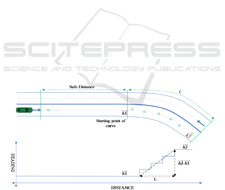
Figure 1: Conceptual diagram showing advance curve speed warning system.
Starting
Point of curve
Safe Distance
Advanced Curve Speed Warning System using Standard GPS Technology and Road-level Mapping Information
465
2 ADVANCE CURVE
DETECTION ALGORITHM
Our proposed advance curve detection algorithm
utilizes reference road direction to detect a possible
curve ahead and warn the driver about the advisory
speed for a given curve at a safe distance before the
curve starts as shown in Figure 1. The safe distance is
assumed to be the distance needed to reduce a
vehicle's speed from its current speed to the advisory
speed of the curve by applying normal braking with
safe deceleration rate. Usually, before applying
brakes, a driver needs a buffer time called reaction
time to adjust to the warning. Therefore, driver’s
reaction time will also be included in determining
safe distance. There are three crucial parts of
advanced curve speed algorithm. First to determine
the advisory speed of a given curve and second to
determine safe distance using vehicle's current speed
and advisory speed for the curve, and a safe
deceleration rate. The third element is the constituents
of the advisory speed warning itself which is issued if
the vehicle’s current speed is higher than the advisory
speed. In the following these three aspects of the
proposed algorithm are explained in detail.
2.1 Advisory Speed for the Curve
We have explored two methods for determining
advisory speed for a given curve. Although, various
vehicles have different capacity to handle speed on
curves, we have assumed just one advisory speed for
all vehicles. To estimate the advisory speed, both
methods obtain specific information from the same
digital map database as we previously used for the
lane departure warning system. In the first method, an
advisory speed is determined using the shape points
for a given curve which we previously used to
determine the reference road direction. However, in
the second method an advisory speed value for a
given curve is directly acquired from the same
mapping database. These two methods are further
described below.
2.1.1 Calculated Advisory Speed
Our proposed algorithm uses reference road direction
to determine the degree of curvature for any given
curved section of the road segment. The degree of
curvature is then used to calculate the advisory speed
for that curved section. Our proposed methodology to
determine the degree of curvature needed to calculate
advisory speed for our proposed system is
schematically shown in Figure 2 where the heading
between two consecutive shape points for a given
road is shown versus distance. The beginning and
ending points of the curved section of the road are
also shown along with the safe distance.
Our previously developed lane departure
detection algorithm can detect the beginning and
ending points of a curve ahead. By determining the
beginning and ending points of a curve, we can
calculate the total length of the curve (L) as well as
the differential heading which is the difference of
initial
heading (h1) at the beginning of the curve and
Figure 2: Schematic diagram showing methodology to determine beginning and ending points of a curve ahead. This will be
needed to determine advisory speed.
VEHITS 2020 - 6th International Conference on Vehicle Technology and Intelligent Transport Systems
466
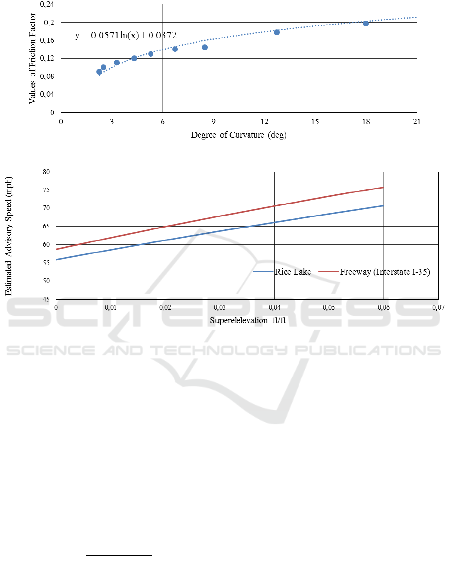
Figure 3: The friction factor vs. degree of curvature.
Figure 4: An Estimated advisory speed vs. Super-elevation values.
final heading (h2) at the end of the curve. Finally, the
degree of curvature (D) which is defined as the
change of heading (in degrees) over 100 ft, is
calculated using equation 1 (AASHTO: A Policy on
Geometric Design of Highways and Streets), where L
is the curve length in feet.
D =
||
(1)
Once the degree of curvature is calculated, it is
used to determine the advisory speed (V) which not
only depends on degree of curvature but also rely on
other factors including super-elevation (e) and road
friction factor (f), and can be calculated using
equation 2 (AASHTO: A Policy on Geometric Design
of Highways and Streets).
=
(
.
)
(
)
()
(2)
Both super-elevation and friction values can be
estimated empirically. According to MnDOT road
design manual, the specific degree of curvature
corresponds to a specific limiting friction factor value
for a given road (S. Glaser et al. 2007). It contains
specific friction factor values for a few discrete values
of degree of curvature ranging from 2 to 21 degrees
(S. Glaser et al. 2007). We have curved fitted the
specified friction factor values to generate a generic
formula to determine friction factor value for a given
degree of curvature as shown in Figure 3 where
friction factor values are plotted versus degree of
curvature.
Although friction factor value is fixed for a given
degree of curvature, the super-elevation value for a
given road can vary between 0 to 6 percent for the
same degree of curvature. There is a possibility that
roads with the same degree of curvature can have
different super-elevation values or vice versa. Most of
the highways and freeways in Minnesota use 6
percent of super-elevation value (maximum
recommended) but a few highways especially the old
ones use a smaller super-elevation value.
Figure 4
shows calculated advisory speed versus super-
elevation values for two curved road segments (Rice
Lake Road and Interstate I-35 near Duluth,
Advanced Curve Speed Warning System using Standard GPS Technology and Road-level Mapping Information
467
Minnesota). The calculated advisory speed of Rice
Lake road ranges from 56 to 71 mph. However, the
actual posted advisory speed for that curved section
is 55 mph. This indicates that a super-elevation value
of 0% is used to calculate the posted advisory speed
for the Rice Lake Road. On the other hand, for the
Interstate section I-35, the actual posted speed is 70
mph while the calculated advisory speed ranges from
58 to 76 mph. Which implies that the 4% super-
elevation value was used to calculate the posted
advisory speed for that segment. Without having the
super-elevation information in advance, we cannot
reliably calculate an advisory speed for a given road.
Although the safest value of super-elevation is 0%
resulting in the least or safest advisory speed for any
given curve. Therefore, we used a super-elevation
value of 0% to calculate advisory speed in our
prototype system. In the cases of two roads (Rice
Lake and I-35), the calculated advisory speed for the
Rice Lake Road was close to the posted speed but
much less for the I-35 curved section which was
actually designed for a higher speed. An advisory
speed using one fixed value of super-elevation i.e.,
0% could vary from the actual posted advisory speed
for any given road. To mitigate this factor and to warn
the driver appropriately, it is best to obtain the actual
posted advisory speed from the digital map database
as explained below.
2.1.2 Acquired Advisory Speed
This method directly extracts posted advisory speed
from the digital mapping database which also has
road level information including advisory speed.
After extracting the advisory speed directly from the
mapping database, our algorithm compares it with the
calculated advisory speed. To be on the safe side, we
used the lower advisory speed whether it is from the
mapping database or from the calculation method for
issuing the warning. After determining the advisory
speed, next step is to find the safe distance before
issuing the warning.
2.2 Safe Distance
Safe distance is calculated using vehicle's current
speed, the advisory speed of the given curve, and a
safe deceleration rate. The current speed of the
vehicle is calculated from the GPS coordinates and
advisory speed is determined as explained above. As
for as the safe deceleration rate is concerned,
according to AASHTO, approximately 90% of
motorists brake with the deceleration rate of more
than 3.4 m/s
2
(S. Glaser et al. 2007). This rate enables
drivers to reduce their speed safely without losing
control. Therefore, 3.4 m/s
2
is used as a safe
deceleration rate to calculate safe distance for our
algorithm. Using current speed, advisory speed, and
safe deceleration rate (a), the safe distance is
calculated by using Equation 3.
(3)
However, Equation 3 does not accommodate
driver’s reaction time. Therefore, an adjustment is
made to include the driver’s reaction time in
calculating safe distance using Equation 4, where T is
the reaction time for the driver. According to
AASHTO, a person can take 0.9 to 2.5 seconds to
react to a warning sign. To be on a safe side, we are
using the longest reaction time (2.5 s) for safe
distance calculations for our system.
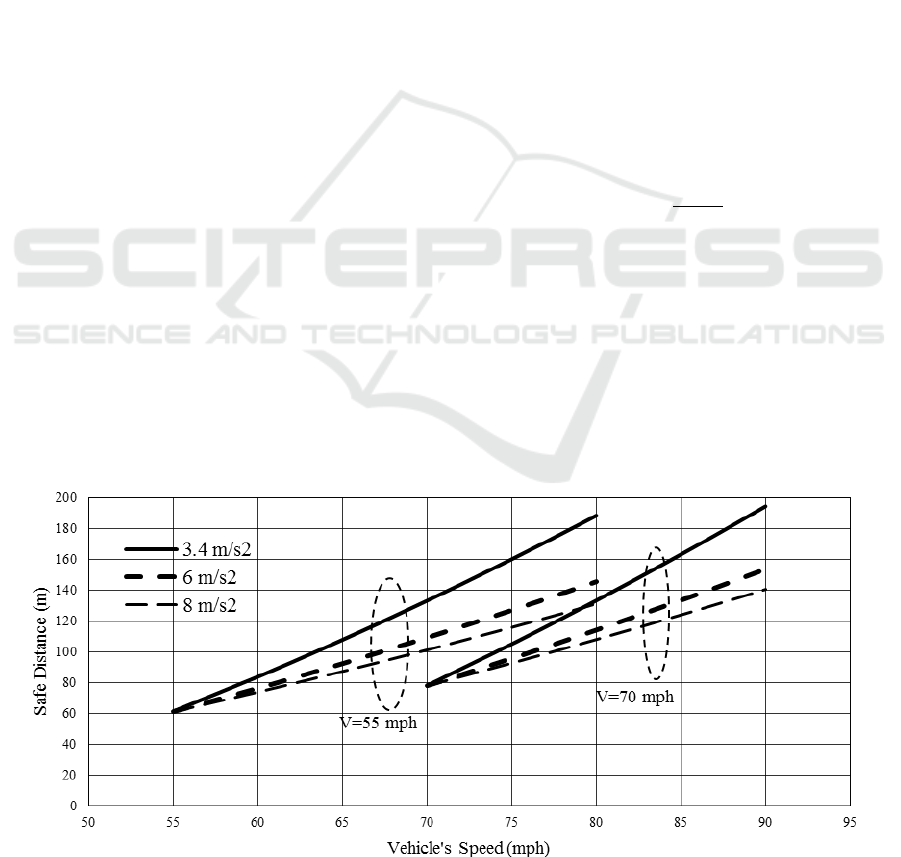
Figure 5: Calculated safe distance vs. vehicle’s current speed for two different advisory speeds.
VEHITS 2020 - 6th International Conference on Vehicle Technology and Intelligent Transport Systems
468
+
× (4)
Figure 5 shows the safe distance vs. vehicle’s
current speed for three different values of
deceleration rate (3.4, 6 and 8 m/s
2
) for each of the
two advisory speeds (55 and 70 mph). Although
system uses 3.4m/s
2
as deceleration rate, the higher
declaration rates (6 and 8 m/s
2
) have been
incorporated for reference only. It is to be noted that
the higher deceleration rates show the usage of
emergency brakes while reducing speed. When the
vehicle is driving at the same speed as the advisory
speed (V=V
C
), safe distance only accounts for
driver’s reaction time and will have some non-zero
value.
2.3 System Warning Generation
Based on safe distance analysis, our algorithm scans
a curve ahead at least half a mile in advance to ensure
that advanced curve warning can be issued in time.
Half a mile criterion gives 30 seconds buffer time at
the speed of 60 mph. Once the advisory speed is
determined and a safe distance is calculated, the
following two possible scenarios are evaluated prior
to issuing the warning.
Vehicle’s current speed is higher than the
advisory speed.
Vehicle’s current speed is less than or equal
to the advisory speed.
In both scenarios, our algorithm recommends the
same warning, however, the safe distance where the
warning will be issued will be different in both
scenarios. Once vehicle approaches at the safe
distance to the curve, the above warning will be
issued.
The warning message comprises of two important
pieces of information, first about the existence of
curve ahead and second about the advisory speed for
that curve. By giving the warning within the safe
distance, our algorithm ensures that the driver has
enough time to adjust vehicle’s speed comfortably.
Our prototype system displays a written warning on
the console for demonstration purposes.
3 FIELD TESTS AND RESULTS
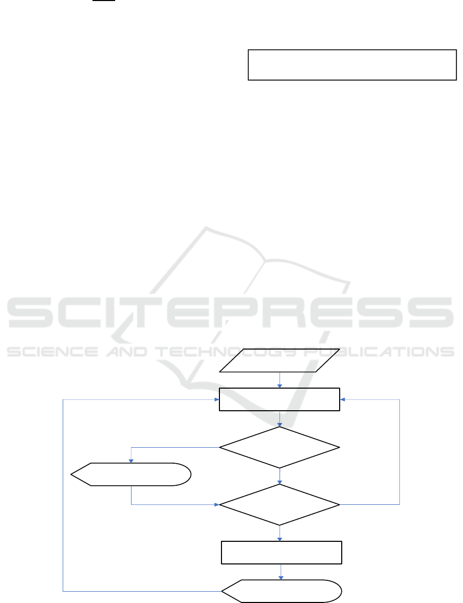
The functional flow diagram for both lane departure
detection and advanced curve speed warning
Figure 6: Flow diagram showing the complete functionality of lane departure warning and advance curve speed warning
systems.
System
Initialization and
Data Processing
Calculate Lateral Deviation
Lane
Departure
Detection
Audible Warning
Curve
Detection
Calculate Safe Distance and
Advisory Speed
Issue Advance
Curve Warning
Yes
No
Yes
No
Curve Ahea
d
Advisor
y
S
p
eed: XX m
p
h
Advanced Curve Speed Warning System using Standard GPS Technology and Road-level Mapping Information
469
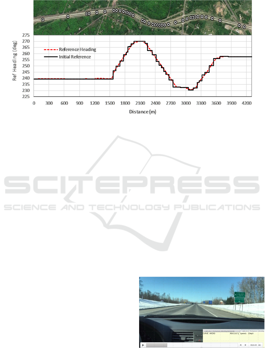
Figure 7: Database heading between consecutive shape points (black) and calculated reference heading (red dashed line)
versus road distance for a 4 km segment of Interstate I-35. The Google Earth view of the corresponding road segments with
shape points are also shown for reference.
algorithms are shown in Figure 6. We used a Savari
MobiWAVE unit to implement our algorithm and
evaluate its performance in the field. The Savari unit
has a built in GPS receiver and processing power to
implement our algorithm. The built-in GPS receiver
had a UBlox LEA-6 chipset which is a common
chipset in many GPS receivers. Please note that the
proposed algorithm can be implemented in any
navigational device having a standard GPS receiver
and necessary processing power.
The prototype system periodically (every 100 ms)
calculates instantaneous lateral distance and
accumulates it over time. If the accumulated lateral
distance crosses certain threshold, the system will
issue an audible warning to alert the driver of
unintentional lane drifting. Simultaneously, the
prototype system also checks if there is any curve
ahead. The system has the capability to differentiate
between curve and straight sections of the road in real
time. If a curve is detected, first its advisory speed is
determined and then a safe distance is calculated
based on vehicle’s current speed and the advisory
speed for the curve. The safe distance calculation
determines when to issue the advance curve speed
warning. In our prototype system, the warning is
issued as soon as the vehicle approaches within the
safe distance from the curve so the driver will have
enough time to reduce the vehicle’s speed. This whole
cycle of calculation is repeated every 100 msec and
appropriate warnings are given when warranted. In
this way, both lane departure and advanced curve
speed warning algorithms works simultaneously.
We tested our prototype system on two different
road segments, a 3 km long segment of Rice Lake
Road in Duluth, MN, and a 4 km long segment of
Interstate I-35 near Duluth, MN. Figure 7 shows the
reference heading for I-35 vs travelled distance as
extracted from the mapping database. The Google
Earth picture of the corresponding section of
Interstate I-35 is also shown on the top of the figure.
The I-35 test segment has three curves in 4 km
segment as can be seen in Figure 7.
The lane width for both road segments was 3.6 m
and the speed limit were 55 MPH for Rice Lake Road
and 70 MPH for Interstate I-35. The vehicle was
driven at about speed limit on both road segments and
many back-and-forth driving runs were made. During
these test runs, whenever, the vehicle was
approaching to a curve, the driver was warned about
the presence of the curve ahead along with its
advisory speed before the curve starts.
Figure 8: Snapshot from field demonstration showing
advanced curve speed warning while approaching a curve.
VEHITS 2020 - 6th International Conference on Vehicle Technology and Intelligent Transport Systems
470

Figure 8 shows a snapshot of the console during
one of our field tests while approaching one of the
three curve sections in the test segment. We evaluated
the accuracy of the algorithm by marking down the
distance where the warning was issued while driving
at different speeds. Each time, the curve was
successfully detected and the warning was shown at
the appropriate safe distance. We also evaluated the
system for lane departure warning by intentionally
making many back and forth lane changes on both
straight and curved sections of the test segment.
Those results have already been published elsewhere
(Muhammad Faizan et al. 2019).
4 CONCLUSIONS
Previously we proposed and demonstrated a novel
algorithm to detect an unintentional lane departure
and warn the driver in time. Now we have added
another feature in this algorithm which can detect an
upcoming curve and determines its advisory speed.
We designed the algorithm for this added feature and
demonstrated in the field by developing a prototype
system. Extensive field tests were performed to
evaluate the efficiency of the newly developed
algorithm on two different road segments. The
advance curve detection algorithm can detect the
upcoming curve and correctly determines its advisory
speed before issuing the appropriate warning at a safe
distance before the curve starts. We have performed
error analysis for the lane departure detection part of
this work but both the temporal and spatial scale
involved in an upcoming curve detection are large
enough to be ignored. An error in an upcoming curve
detection, can be up to 25 m in location which
translates to 1 second in time, is insignificant for
this feature.
ACKNOWLEDGEMENTS
The authors wish to acknowledge those who made
this research possible. The study was funded by the
Minnesota Department of Transportation (MnDOT)
and Minnesota Local Research Board (LRRB).
REFERENCES
C. Maag, D. Muhlbacher, C. Mark and H. P. Kruger,
Studying Effects of Advanced Driver Assistance
Systems (ADAS) on Individual and Group Level Using
Multi-Driver Simulation, IEEE Intelligent
Transportation Systems magazine, vol. 4, no. 3, pp.
45-54, Fall 2012.
Driving down lane-departure crashes: A national priority.
(2008). Washington, DC: American Association of
State Highway and Transportation Officials.
Preston, H., and T. Schoenecker, Potential Safety Effects of
Dynamic Signing at Rural Horizontal Curves,
Minnesota Local Road Research Board. St. Paul, MN,
December 1999.
D. D. Salvucci, Inferring driver intent: A case study in lane-
change detection, Proc. Human Factors Ergonomics
Society 48th Annu. Meeting, New Orleans, LA, 2004,
pp. 2228–2231.
N. Kuge, T. Yamamura, and O. Shimoyama, A Driver
Behavior Recognition Method Based on a Driver
Model Framework. Warrendale, PA: Soc. Automot.
Eng., 1998.
J. McCall and M. M. Trivedi, Visual context capture and
analysis for driver attention monitoring, Proc. IEEE
Conf. Intelligent Transportation Systems, Washington,
DC, Oct. 2004, pp. 332–337.
F. Heimes and H.-H. Nagel, Towards active machine-
vision-based driver assistance for urban areas, Int. J.
Comput. Vis., vol. 50, no. 1, pp. 5–34, Oct. 2002.
W. Kwon and S. Lee, Performance evaluation of decision-
making strategies for an embedded lane departure
warning system, J. Robot. Syst., vol. 19, no. 10, pp.
499–509, Sep. 2002.
Federal Highway Administration, FHWA Roadway
Departure Strategic Plan. Washington, DC: March
2013.
Cicchino, J. (2018). Effects of lane departure warning on
police-reported crash rates. Journal of Safety Research,
66, pp.61-7.
Xiangjing An, Mo Wu and Hangen He, A Novel Approach
to Provide Lane Departure Warning Using Only One
Forward-Looking Camera, International Symposium
on Collaborative Technologies and Systems (CTS'06),
2006, pp. 356-362.
Pei-Yung Hsiao and Chun-Wei Yeh, A Portable Real-Time
Lane Departure Warning System based on Embedded
Calculating Technique, 2006 IEEE 63rd Vehicular
Technology Conference, Melbourne, Vic., 2006, pp.
2982-2986.
B. Yu, W. Zhang and Y. Cai, A Lane Departure Warning
System Based on Machine Vision, 2008 IEEE Pacific-
asia Workshop On Computational Intelligence and
Industrial Application, Wuhan, 2008, pp. 197-201.
Y. C. Leng and C. L. Chen, Vision-based lane departure
detection system in urban traffic scenes, 2010 11th
International Conference On Control Automation
Robotics & Vision, Singapore, 2010, pp. 1875-1880.
P. Lindner, E. Richter, G. Wanielik, K. Takagi and A.
Isogai, Multi-channel lidar processing for lane
detection and estimation, 2009 12th International IEEE
Conference On Intelligent Transportation Systems, St.
Louis, MO, 2009, pp. 1-6.
S. Glaser, L. Nouveliere and B. Lusetti, Speed Limitation
Based on an Advanced Curve Warning System, 2007
Advanced Curve Speed Warning System using Standard GPS Technology and Road-level Mapping Information
471

IEEE Intelligent Vehicles Symposium, Istanbul, 2007,
pp. 686-691.
R. Yoneda, K. Okuda and W. Uemura, A tight curve
warning system using FSK visible light and road-to-
vehicle communication, 2013 IEEE Third International
Conference on Consumer Electronics, Berlin (ICCE-
Berlin), Berlin, 2013, pp. 1-3.
S. Rogers and Wenbing Zhang, Development and
evaluation of a curve rollover warning system for
trucks, IEEE IV2003 Intelligent Vehicles Symposium.
Proceedings (Cat. No.03TH8683), Columbus, OH,
USA, 2003, pp. 294-297.
Qin, Xiao & Zhang, Shaohu & Wang, Wei. (2015).
Advanced Curve-speed Warning System Using an In-
Vehicle Head-Up Display.
S. Glaser, L. Nouveliere and B. Lusetti, Speed Limitation
Based on an Advanced Curve Warning System, 2007
IEEE Intelligent Vehicles Symposium, Istanbul, 2007,
pp. 686-691.
DaimlerChrysler AG (2018). Vehicle With Optical
Scanning Device For A Lateral Road Area.
US006038496A.
J. M. Clanton, D. M. Bevly and A. S. Hodel, A Low-Cost
Solution for an Integrated Multisensor Lane Departure
Warning System, IEEE Transactions On Intelligent
Transportation Systems, vol. 10, no. 1, pp. 47-59,
March 2009.
S. Glaser, L. Nouveliere and B. Lusetti, Speed Limitation
Based on an Advanced Curve Warning System, 2007
IEEE Intelligent Vehicles Symposium, Istanbul, 2007,
pp. 686-691.
S. Hussain, M. Faizan and M.I. Hayee. Real-time relative
lane and position identification of surrounding vehicles
using GPS and DSRC based vehicle-to-vehicle
communication. Presented at the proceedings of IEEE
Conference on Communications, Kansas City, MO.,
May 2018.
Muhammad Faizan, S. Hussain and M.I. Hayee, Design
And Development Of In-vehicle Lane Departure
Warning System Using Standard GPS Receiver.
Transportation Research Record, Journal of
Transportation Research Board, I-9, 2019.
A Policy on Geometric Design of Highways and Streets,
2018, 7
th
Edition: American Association of State
Highway and Transportation Officials.
VEHITS 2020 - 6th International Conference on Vehicle Technology and Intelligent Transport Systems
472
