
Application Lifecycle Management for Industrial IoT Devices in Smart
Grid Use Cases
Stephan Cejka
1
, Florian Kintzler
1
, Lisa M
¨
ullner
1
, Felix Knorr
1
, Marco Mittelsdorf
2
and J
¨
orn Schumann
2
1
Siemens AG
¨
Osterreich, Vienna, Austria
2
Fraunhofer Institute for Solar Energy Systems ISE, Freiburg, Germany
{marco.mittelsdorf, joern.schumann}@ise.fraunhofer.de
Keywords:
Software Management, Software Rollout, Cyber-physical System, Application Lifecycle Management,
Dependability.
Abstract:
Complex cyber-physical systems like the Smart Grid, in which Industrial Internet of Things (IIoT) technology
is used, require advanced software maintenance mechanisms to remain dependable and secure. In this paper,
requirements and tasks for an application lifecycle management for IIoT use cases, with special focus on the
domains of Smart Grid and Smart Buildings, are defined and state-of-the-art software deployment processes
from IoT use cases are evaluated for usage in those domains. As there is no suitable framework, an approach
for the deployment of OSGi components is described. On top of such software deployment tools, a knowledge-
based software management framework that utilizes domain specific knowledge to create and execute software
rollout plans will be presented. Thus, dependencies can be managed on device, system and domain level.
1 INTRODUCTION
Cyber-physical systems (CPS) require careful main-
tenance of all parts of the system to achieve a prede-
fined level of dependability and security. This main-
tenance includes rollout, update, and decommission-
ing of software on field devices. The usage of Inter-
net of Things technology in industrial cyber-physical
systems (Industrial Internet of Things – IIoT) signif-
icantly emphasizes this requirement since the num-
ber of small and medium sized devices that may be
affected by security issues or bugs preventing cor-
rect operation increases significantly (Razzaq et al.,
2017). One of these systems is the Smart Grid (Yu
and Xue, 2016), in which field devices monitor and
control hardware to generate, transmit, store, provide,
and consume energy. The transition from the tradi-
tional grid to the Smart Grid includes equipping sec-
ondary substations, located on the borders between
the medium and the low voltage grid, with mecha-
nisms to allow software modules to be installed on
demand and maintained centrally from a remote op-
erator (Faschang et al., 2017).
In this paper, processes for the large scale rollout
of software applications, especially in use cases of
energy and grid management are investigated. They
involve a high number of intelligent Secondary Sub-
stations (iSSNs) and an even higher number of Build-
ing Energy Management Systems (BEMSs) using a
central control center for the supervision and man-
agement of software components’ operation on the
devices in the field (Kintzler et al., 2018). Stable
and resilient system operation is required in this set-
ting where communication systems are used for Smart
Grid runtime operation (such as monitoring), con-
trols and Information and Communication Technol-
ogy (ICT) maintenance (such as application deploy-
ment, patching, and remote configuration). In con-
trast to Internet of Things use cases, the installation
of a module does not only affect one device. Indus-
trial IoT applications interact with external systems
(e.g., the power grid) which may become a hidden
communication channel (Kintzler et al., 2018). It is
thus important to ensure that the running apps work
together correctly. Therefore, the deployment process
must be resilient to faults and attacks in both the ICT
and the power grid system.
This paper defines requirements and tasks for an
application lifecycle management for IIoT use cases,
especially with focus on the domain of Smart Grid
and Smart Buildings. An overview on software de-
ployment processes in the Smart Grid and the cus-
Cejka, S., Kintzler, F., Müllner, L., Knorr, F., Mittelsdorf, M. and Schumann, J.
Application Lifecycle Management for Industrial IoT Devices in Smart Grid Use Cases.
DOI: 10.5220/0009389602570266
In Proceedings of the 5th International Conference on Inter net of Things, Big Data and Security (IoTBDS 2020), pages 257-266
ISBN: 978-989-758-426-8
Copyright
c
2020 by SCITEPRESS – Science and Technology Publications, Lda. All rights reserved
257

tomer domain is given (Section 2). As no tailored pro-
cess for those domains exists yet, state-of-the-art soft-
ware deployment processes from IoT use cases are
evaluated (Section 3). Afterwards, an approach for an
OSGi-based deployment is presented (Section 4). Fi-
nally, an approach to include domain-specific knowl-
edge to plan and execute software rollouts is intro-
duced (Section 5).
2 APPLICATION LIFECYCLE
MANAGEMENT
Several definitions of the terms software distribution,
software deployment, and its processes exist (Dearle,
2007; Arcangeli et al., 2015). For example, Arcan-
geli et al. define software states (deployable, inactive,
active) and activities that change the state. Not only
does that include the activity of distribution, but also
the continuous maintenance of the software and its de-
commissioning. Furthermore, they consider changes
on the physical infrastructure which require redistri-
bution of software. The OSGi lifecycle (OSGi Al-
liance, 2018) provides a similar concept and intro-
duces further states (installed, resolved, starting, ac-
tive, stopping, uninstalled). In the following sections,
requirements for an IIoT application lifecycle man-
agement as well as typical software maintenance tasks
a system needs to fulfill in a resilient and secure man-
ner are defined.
2.1 Requirements
Main requirements for a provisioning mechanism are:
R1 Scalable Device Management. A central control
center shall supervise and manage the operation
of software components on a high number of field
devices, posing the requirement of a scalable so-
lution. The devices’ state, including running soft-
ware components and their configuration, needs
to be communicated to the backend system.
R2 Automatic Deployment. Software components
and their configurations need to be deployed to
the field devices while reducing maintenance ef-
fort and cost. Thus, it should be avoided to require
staff on-site for the majority of such tasks.
R3 Modular System. Devices in the field may have
only a limited bandwidth. Modular software com-
ponents, both small in their duties and size, allow
for a bandwidth efficient transmission. Further-
more, this simplifies to compose required features
of a device on demand.
R4 Dependency Management. Possible dependen-
cies between applications shall be resolved auto-
matically during the installation process.
R5 Automatic Updates, Automatic Configuration.
Deployed software components may be stopped at
a later time, they may be updated to a newer ver-
sion or its configuration may be changed. Unnec-
essary transmission of unaffected software com-
ponents can be avoided best in a modular system
(R3); thus, only the affected components need to
be substituted while all others continue to run.
R6 Automatic Rollback. Automatic rollback proce-
dures shall be provided in case of a failure of the
installation process to restore the previously veri-
fied working state of the system.
R7 Resilience and Security. The rollout process
shall be resilient against faults of and attacks
against the ICT network and the power grid. Com-
munication needs to be secured as well as bad
network connections need to be taken care of.
The software repository shall only be accessible
for authenticated targets and all resources shall be
signed to ensure integrity and authenticity.
2.2 Application Lifecycle Management
Tasks
In the described setting, applications shall be in-
stalled/updated/etc. from a remote backend system to
enhance or modify the functionality of the target sys-
tem. Following application lifecycle management and
provisioning tasks can be identified (Faschang et al.,
2017):
1. Installation of a software module
2. Start of this software module
3. Stop of this software module
4. Uninstallation of this software module
5. Update of this (possibly running) software mod-
ule
6. Configuration of this (possibly running) software
module
7. Information about the current state of the software
modules (e.g., by utilizing a periodically running
health check)
There are different approaches of managing the
lifecycle of applications, most of which are designed
for a specific programming language or a specific
runtime environment. They share lifecycle states
like stopped, started/running, paused, and failure and
IoTBDS 2020 - 5th International Conference on Internet of Things, Big Data and Security
258
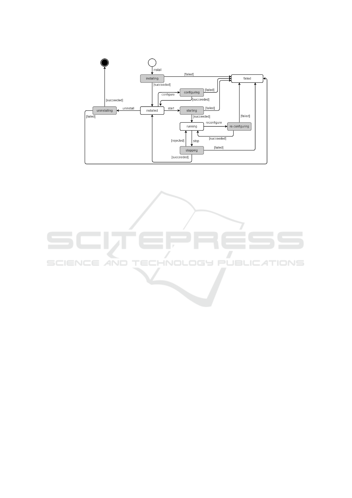
Figure 1: A sample application lifecycle graph.
transitions between these states like installing, start-
ing, stopping, configuring etc., but they slightly dif-
fer in the details. Based on the work of Arcan-
geli et al. (Arcangeli et al., 2015), the OSGi lifecy-
cle (OSGi Alliance, 2018), and the Docker lifecycle,
a combined application lifecycle graph was developed
considering the introduced tasks (Figure 1). Within
additional intermediate states (shown in grey) the re-
ceived task is executed; each of these states could ei-
ther be successful resulting in a persistent state, or
could fail resulting in the failed state, which requires
further action, possibly including manual intervention
by the operator.
In the most usual case, a software update task
refers to a sequence of stopping the old module if
it was currently running, persisting its current state
and uninstalling the module afterward; the new mod-
ule is installed, configured according to its persisted
state and started if the old module was running be-
fore. Thus, the module continues to work accordingly
and its down-time can be minimized. In contrast, a
software configuration task, by design, should be less
intrusive than a software update task; i.e., it should
not be required to restart the running module.
2.3 Implementation and
Communication Approaches
The defined tasks shall be triggered by a backend op-
erator, for example, by using a web dashboard. The
application itself stays uninterpreted on the backend
side; it may be an executable, an archive or other data
– for the backend it is just a Binary Large Object
(BLOB) not requiring a defined format. Configura-
tion shall preferably be in a platform-independent for-
mat (e.g., JSON); the device system is responsible for
the proper handling of the BLOB and the configura-
tion once the files have been transferred to the device.
For the transfer of applications and configurations two
possible approaches exist:
Push Approach: The backend initiates the transmis-
sion, commands or information requests are sent
immediately to the device.
Pull Approach: The device initiates the transmis-
sion. It periodically requests the backend to trans-
mit pending changes; in this setting, however, the
backend may not always be aware of the device’s
current state (cf. devices shadows).
Especially in the Smart Grid and Smart Building
context, it is not always possible or desired to keep
a permanent connection between the operator back-
end and the devices. Thus, a pull approach is usually
preferred.
3 STATE OF THE ART
The architecture of a system generally consists of a
central backend and control system in the operator’s
sphere, responsible for the management of software
components on the field devices. Many target devices
in the field are controlled by one backend system;
they are connected with the backend by one of var-
ious possible communication channels, where mes-
sages and artifacts are exchanged. Target systems al-
low for modular applications (R3), thus the number of
concurrently executed applications may be high. De-
pending on the use case and the used hardware com-
ponents, the implementation of applications can dif-
fer (e.g., OSGi modules or Docker containers). These
systems have to include mechanisms for automated
Application Lifecycle Management for Industrial IoT Devices in Smart Grid Use Cases
259

application provisioning, remote and automatic con-
figuration and update of services to minimize engi-
neering effort (Plug & Automate). The enumerated
tasks (T1–T7) can either be initiated manually by a
human user or automatically via some (scheduled)
scripts. On the target system side, a device appli-
cation management is responsible for executing re-
ceived commands and replying the status to the ini-
tiator. For an installation task, for example, it down-
loads the application from the backend repository; for
example, for OSGi-based deployments from an OSGi
Bundle Repository (OBR) implementation.
Next, existing IoT solutions are evaluated whether
they are suitable for the listed software management
requirements in the field of IIoT. While the list is not
exhaustive, it provides a good overview on the spec-
trum of currently available solutions and their fea-
tures. Those tools can be divided into software dis-
tribution tools (Section 3.1), and modular application
servers in which applications can be installed/updated
(Section 3.2). Furthermore, approaches for such use
cases by the cloud providers AWS, and Microsoft are
discussed (Section 3.3).
3.1 Software Distribution Tools
3.1.1 Eclipse hawkBit
Eclipse hawkBit
1
is an open source project aiming to
be a domain-independent open platform for provid-
ing software updates in IoT systems. It can either be
used separately or included into existing systems by
providing a RESTful management interface for de-
vice integration. Furthermore, a web dashboard can
be used as user interface. hawkBit does not provide
any dependency management; it completely focuses
on update distribution, while not requring knowledge
on the artifacts’ structure (hence providing domain in-
dependence). However, main provisioning features
are not well supported: While installing/updating a
software is the main function, neither a later uninstal-
lation/removal of an installed application nor an ex-
plicit start or stop is possible. In result, main require-
ments of application lifecycle management can not be
fulfilled.
3.1.2 balena
balena
2
is a container-based platform for the deploy-
ment of IoT applications. The device needs to be
set up with balenaOS, an operating system, optimized
for running Docker containers on embedded devices.
1
https://www.eclipse.org/hawkbit/
2
https://www.balena.io/
Code is pushed to balena’s build servers, results are
stored as Docker containers in a centralized Docker
registry and delivered to the devices in that form; its
application lifecycle is thus linked to the Docker con-
tainer lifecycle. While some states are named differ-
ently, they are nevertheless representable by the sug-
gested lifecycle shown in Figure 1. Devices are man-
aged and monitored by centralized web-based dash-
board, the fleet manager. On the device side, a su-
pervisor container serves as agent, responsible for
managing application updates and reporting the de-
vice’s status. balena supports diff-based container
updates, i.e., when updating, a device does not need
to download the entire new container, but only the
changed parts – useful especially for devices con-
strained by connectivity or bandwidth. Furthermore,
balena provides four update strategies: download-
then-kill, kill-then-download, delete-then-download,
hand-over; they shall be utilized depending on the de-
vice’s available memory, storage, and processor, as
well as on the acceptable down-time during an appli-
cation’s update. Once a new version of an applica-
tion container is available in the registry, the supervi-
sor automatically downloads it and replaces the run-
ning container employing the defined update strategy.
Unfortunately, the restriction to Docker containers as
well as the binding to a specific operating system on
the devices limits the applicability of this approach.
3.1.3 SWUpdate
SWUpdate
3
is an open source software to update the
firmware of embedded systems. A Linux update agent
supports local and remote updates by using multi-
ple update strategies. For a customization of the up-
date process, SWUpdate supports pre- and post-install
scripts. Furthermore, SWUpdate uses a stand-alone
software application for the installation of software
onto the desired storage. Before the application in-
stalls the software, it determines whether the software
is installable and suitable for the device’s hardware.
SWUpdate also supports the update of single files in
a filesystem, mostly for updating the configuration of
an application. In general, SWUpdate is tailored to
firmware applications and does not provide any appli-
cation lifecycle management functionality.
3.1.4 Gridlink Application Framework
Provisioning
Apart from the seven application lifecycle manage-
ment tasks that were enumerated earlier in this pa-
per, Faschang et al. introduced a provisioning system
3
https://github.com/sbabic/swupdate/
IoTBDS 2020 - 5th International Conference on Internet of Things, Big Data and Security
260

for Gridlink, a framework for modular Java applica-
tions (Faschang et al., 2017). Tasks are initiated by
the remote operator dashboard and communicated to
the device via the eXtensible Messaging and Presence
Protocol (XMPP). Additional features include the de-
tection of dependencies and the configuration of mod-
ules to be installed. Though all of the mentioned tasks
were implemented, their provisioning system is very
tightly connected with the Gridlink system, thus man-
ageable applications are restricted to Gridlink mod-
ules, incompatible with OSGi.
3.1.5 iSSN Application Lifecycle Management
Gawron-Deutsch et al. introduced a generic im-
plementation for application lifecycle management
in IIoT use cases including an optional App Store
(Gawron-Deutsch et al., 2018). Purchased applica-
tions are downloaded by the Application Lifecycle
Management Service to the local application reposi-
tory, situated within the operator’s backend. The op-
erator manages several field devices using an user in-
terface on the backend side; enumerated application
lifecycle tasks are issued there and communicated to
the Application Lifecycle Management Agent running
on the device. There, specific shell scripts based on
file type and task (e.g., docker-install.sh for an
installation task of a Docker container) are called.
Hence, a generic approach for high numbers and types
of applications is provided. However, while it is not
restricted to a certain programming language or plat-
form, it is not suited for modular systems like OSGi
deployments.
3.2 Application Servers
3.2.1 Apache Karaf
Apache Karaf
4
extends the OSGi platform by addi-
tional features like hot-deployment, provisioning and
management. It can be used as a container for a wide
range of Java applications like OSGi, Spring and Web
Application Archive (WAR). Each Karaf installation
has a hot-deployment-folder; resources placed at this
location are automatically installed to the container.
Local management tools, such as the Karaf Decanter,
are based on the Java Management Extensions (JMX)
and provide monitoring capabilities of local deploy-
ments. Currently, the ecosystem does not provide a
central management of multiple installations. Fur-
thermore, Karaf does not support strategies for error
handling, such that in case of a failed deployment, the
administrator needs to solve the issue.
4
https://karaf.apache.org/
3.2.2 Eclipse Virgo
Eclipse Virgo
5
is a module-based Java application
server to develop, deploy, and service enterprise Java
and Spring applications. It uses a pipeline with sev-
eral stages for deploying artifacts. Various other types
of artifacts are supported (e.g., OSGi bundles, WAR
files), and user-defined artifact types can be added. Its
lifecycle includes an additional “resolved” step and
is apart from that consistent with Figure 1. Further-
more, Virgo includes dependency management and
hot deployment abilities; however, as it only allows to
deploy and undeploy applications, the required tasks
cannot be completely fulfilled.
3.3 Cloud-provider Solutions
In cloud-edge architecture settings, field devices con-
nect to a backend or management software on the
edge and not directly to the cloud. Thus, field de-
vices do not necessarily maintain a permanent con-
nection to the cloud or to the Internet at all. The trend
of moving computation tasks from the cloud to the
edge for reduced end-to-end latency, continuous ser-
vice without permanent connection to the cloud, opti-
mized usage of network bandwidth, and reduction of
costs (Noghabi et al., 2018) has also been addressed
by the leading cloud providers Amazon Web Services
(AWS) and Microsoft Azure. Thus, they have intro-
duced their own tool set for integration and manage-
ment of edge infrastructures.
3.3.1 AWS IoT Greengrass
AWS IoT Greengrass
6
is Amazon Web Services’ tool
for the edge extending the AWS IoT SDK. Two types
of devices can be distinguished: (i) a Greengrass
Core (GGC) Device, and (ii) many IoT (field) devices
that together form a Greengrass Group. The GGC
contains a local MQTT (Message Queue Telemetry
Transport) broker providing local communication as
well as communication with the AWS cloud such that
not every device requires a direct or permanent in-
ternet connection. Using Greengrass, local Lambda
functions can be deployed to the edge; however, as the
GGC is the only device that can be reached, only on
this device a Lambda function can be executed. Thus,
software cannot be rolled out to any other device in
the group. Furthermore, Greengrass supports instal-
lation and uninstallation only; application execution
and lifecycle management are thus only restricted.
5
https://www.eclipse.org/virgo/
6
https://aws.amazon.com/greengrass/
Application Lifecycle Management for Industrial IoT Devices in Smart Grid Use Cases
261

Table 1: Main features of the evaluated deployment tools.
Deployable Components Key features Availability
Software Distribution Tools
Eclipse hawkBit not restricted (using Software
Structure Definition)
interfaces for easy extensibility; no dependency management,
insufficient support for lifecycle tasks
open source
balena Docker containers programming language agnostic, designed specifically for em-
bedded devices, requires balenaOS as host operating system
partially open
source
SWUpdate especially firmware images update of embedded systems’ firmware with built-in double-
copy strategy
open source
Gridlink Provisioning Gridlink modules as JAR file, JSON
configuration
uses XMPP to deploy software artifacts, monitoring dashboard,
dependency management
closed source
iSSN Application Life-
cycle Management
not restricted (using shell scripts) deploys arbitrary software artifacts by specific shell scripts,
monitoring dashboard
closed source
Application Servers
Apache Karaf Karaf features (e.g., OSGi bundles,
Spring, Web Application Archives)
extends basic OSGi platform by additional features and addi-
tional tools
open source
Eclipse Virgo OSGi bundles, configuration files,
arbitrary artifacts, groups of arti-
facts
module-based Java application server supporting various types
of artifacts
open source
Cloud-provider solutions
AWS IoT Greengrass local Lambda functions deployment is possible to a specific device only closed source
Azure IoT Edge local Azure functions deployment to an IoT edge device running Azure IoT edge run-
time
closed source
The AWS Serverless Application Repository
7
is com-
parable to an App Store for serverless applications
(i.e., Lambda functions). Although actually designed
as a repository for ”normal” AWS Lambda functions,
local Lambdas for the GGC device could also be re-
trieved there. As furthermore each device has its own
shadow in the cloud (and also on the GGC), its config-
uration (which in principle is a JSON file) can be up-
dated and distributed to the device, regardless whether
it is currently connected to the cloud or not – the de-
vice will be synchronized with its shadow on the next
connection.
3.3.2 Azure IoT Edge
Azure IoT Edge
8
is the comparable tool to AWS
Greengrass in Microsoft Azure IoT providing server-
less execution on the edge. Modules in form of con-
tainers can be deployed to the edge. Furthermore, a
function comparable to AWS’ local Lambda functions
is in public preview.
7
https://aws.amazon.com/serverless/serverlessrepo/
8
https://azure.microsoft.com/services/iot-edge/
4 OSGi DEPLOYMENT PROCESS
The BEMS plays an important role regarding grid sta-
bility and integration of renewable energies. It act as
communication center within the building and is able
to perform load management tasks. Such tasks can
be motivated by local optimization goals (e.g., maxi-
mization of its own PV consumption) or triggered by
remote actors like the distribution system operator or
the iSSN to stabilize the grid. Thus, the BEMS needs
to support various communication protocols to inter-
act with devices from building and remote systems,
and it needs to be extensible for customized applica-
tions.
In the previous section, several state-of-the-art
tools in the area of software deployment on both the
control (e.g., Eclipse Hawkbit) and the controlled side
(e.g., Apache Karaf) of the system have been de-
scribed. However, not all requirements and tasks can
be fulfilled by the frameworks in evaluation: Most
of the frameworks show only limited support for the
expected lifecycle tasks: issuing an installation task
usually already includes the start of the module, and
modules cannot be stopped once running. Further-
IoTBDS 2020 - 5th International Conference on Internet of Things, Big Data and Security
262
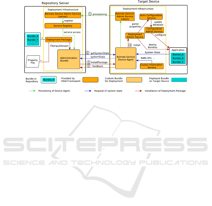
Figure 2: OSGi infrastructure - repository server and target.
more, most frameworks have only limited support of
different deployable component types or they do not
allow a central management of multiple devices.
Due to the popularity of OSGi in the customer do-
main and the lack of a satisfying solution, we propose
an OSGi-based deployment process which considers
the aforementioned requirements R1-R7. The OSGi
Service Platform is a module system for the Java
programming language which allows a dynamic inte-
gration and remote management of software compo-
nents. The OSGi specification is driven by the OSGi
Alliance whose mission is to create open specifica-
tions for network delivery of managed services to lo-
cal networks and devices. OSGi has been adopted for
solutions in IoT, Machine-to-Machine (M2M), Smart
Home, Energy Management, Smart Meters, Health-
care, Automotive and various other domains.
4.1 Architecture
The proposed architecture is depicted in Figure 2. It
consists of a server and a client part with different
orchestrations of standardized OSGi services defined
in the OSGi Compendium Release 7 (OSGi Alliance,
2018). The server part represents the repository server
with released OSGi bundles and project-specific prop-
erty files. A target device is a connected node with its
own OSGi framework running.
The Deployment Package represents the standard-
ized deploy unit of the OSGi framework and contains
multiple OSGi bundles together with their project-
specific property files. A bundle is a Java Archive
(JAR) extended by OSGi-related meta data that may
contain Java classes, embedded JAR files, native code
and other resources. To keep the deployment pro-
cess as modular as possible, only cohesive compo-
nents should be put together in the same deployment
package.
The Device Agent provides a service interface
which handles all interactions between the target de-
vice and the repository server. This interface defines
methods for monitoring the system state with addi-
tional device information and for installing deploy-
ment packages. The device agent runs on the target
device and implements this interface to export its im-
plementation into the runtime system for remote ac-
cess.
The Administration Bundle allows the manual ex-
ecution of deployment tasks over the command line.
Every connected device can be accessed dynamically
through this bundle by importing the implementation
of the Device Agent, after the device connected with
the Repository Server. All imported implementations
are collected in a list and every deployment step will
be executed for all entries.
4.2 Deployment
The interactions between the Repository Server and
Target Device are shown in Figure 2 with different
types of arrows.
4.2.1 Provisioning of the Device Agent
The provisioning activity is marked with (1) in Fig-
ure 2 and done by using the Remote Service Admin
Service. The same bundle is located on both sides,
but started one time as server and the other times as
Application Lifecycle Management for Industrial IoT Devices in Smart Grid Use Cases
263
UI / Controlling & Monitoring
Resiliency
Analysis
Knowledge
Service
Assisted Planning
Execution
Monitoring Services Action Services
Plan
Evaluation
Simulation /
Digital Twin
Software Management System A Device A.1 Device A.2
Device B.1 Device B.2 Device B.3
...
...
Physical System
(e.g. transformer,
power lines etc.)
Monitoring Actions
Software Management System B
Monitoring Actions
M AM
AM
Monitoring Actions
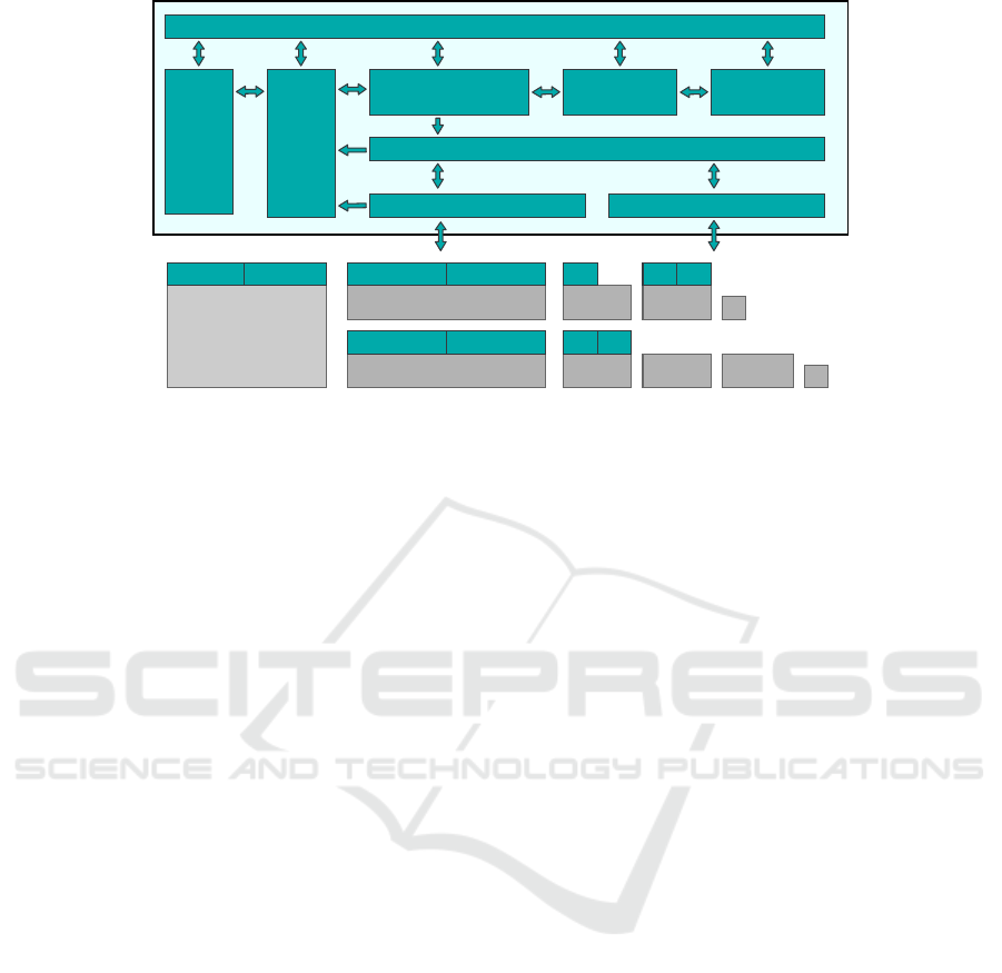
Figure 3: KBSM Framework.
client on every device. This service registers the im-
plementation of the individual Device Agent over the
network in the local Service Registry of the Reposi-
tory Server. This way, the administration bundle gets
access to every device agent.
4.2.2 Monitoring the System State
For requesting device information as well as the
system state of the connected devices the interface
method marked with (2) is used. This information is
needed to evaluate a stable state for installing a bun-
dle on the device. The system state is derived from
the current state of the installed bundles. Information
like available RAM or CPU workload is delivered by
the Cluster Information Service.
4.2.3 Installation of a Deployment Package
If the device is in a stable state for installing a De-
ployment Package, another interface method (3) can
be used to transfer the package over the network to the
Device Agent. The Device Agent will then call the lo-
cal Deployment Admin Service (4) to install it. The
bundles from the package will be directly installed
in the framework, while the delivered property files
are parsed with the Auto Configuration Service. This
service updates the property database of the Config-
uration Admin Service with the new entries. After-
wards, the Configuration Admin Service configures
every bundle, which subscribed the updated proper-
ties. At the end of the procedure an installation feed-
back (5) is given to the Repository Server. This can
be used for visual representation and to initiate a soft-
ware rollback at the target in case of an error.
5 KNOWLEDGE-BASED
SOFTWARE MANAGEMENT
The analyzed management systems to rollout soft-
ware to one or more devices cover different levels
and areas of dependency management. However, for
complex CPSs there are additional dependencies be-
yond of state-of-the-art software rollout systems’ sup-
port. These software dependencies with respect to in-
terfaces and functionality range from the device level
(dependencies to the applications’ runtime environ-
ment like drivers, configured sensors etc.) via the
system level (protocols, services etc.) up to the do-
main level (functional dependencies with respect to
the controlled physical system; for example, two con-
troller applications on separate devices should not try
to control the same physical parameters). To ensure
a given level of dependability of the CPS, during and
after the software rollout, it is important to cover de-
pendencies on all of these levels, rather than focusing
on one of the levels alone.
If a diverse set of devices is used in CPSs, it is
likely that there will also be the need of a diverse
set of software deployment systems, since there are
differing requirements for devices’ types with diver-
gent hardware. For example, resource-restricted IoT
devices, sending sensor measurements via a wire-
less protocol, do not provide the resources to run
containerized applications and can thus not be man-
aged by a Kubernetes backend. However, managing a
state-of-the-art edge device using a firmware manage-
ment tool that flashes the whole device every time one
of the software components needs an update, leads to
an unnecessary outage of functionality that is not af-
fected by the software change. In addition, none of
IoTBDS 2020 - 5th International Conference on Internet of Things, Big Data and Security
264
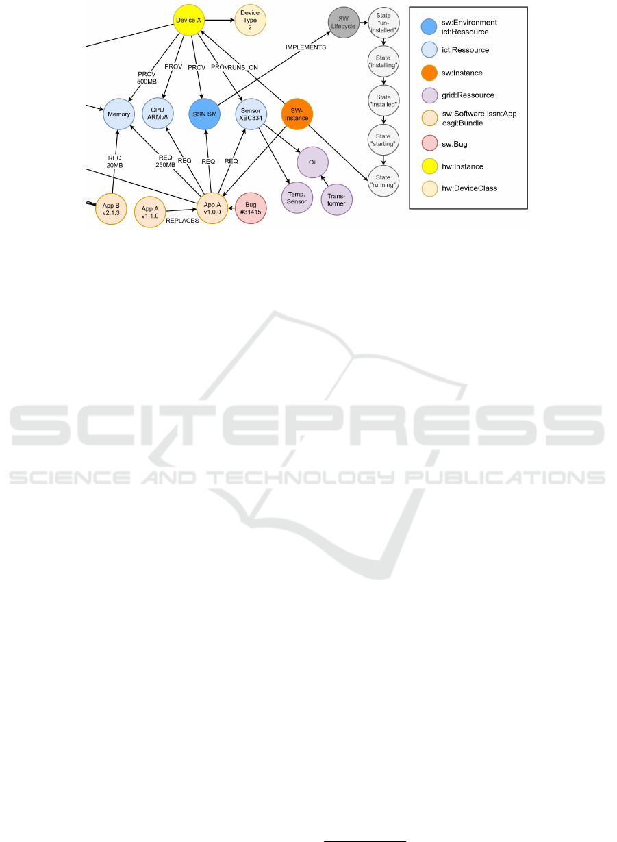
Figure 4: Subset of a knowledge graph stored in the Knowledge-Based Software Management backend.
the analyzed systems are able to include knowledge
about the physical environment and the functions of
the software into the software rollout planning and
execution. Examples for these properties are: band-
width and availability of communication connections,
connection of two different controllers to the same
physical system (possible interference of control ac-
tions), or constraints that could prevent updates of a
software component in a given system state.
To resolve the described limitations, an additional
layer of software management is proposed which gen-
erates and executes software rollout plans using exist-
ing software management systems. The knowledge-
based software management (KBSM) layer as shown
in Figure 3 utilizes knowledge about the setup of the
CPS and its components for the planning process,
which includes knowledge about the underlying soft-
ware deployment processes themselves.
Ontologies are used to describe the system’s com-
ponents and their relations in the Knowledge Service.
This covers properties of software components (size,
memory usage etc.), of computation devices (avail-
able memory, software environment), the controlled
physical system (tapped transformers, power lines,
power switches etc.), the acting roles and the pro-
cesses executed in the system etc. The knowledge
thus consists of static knowledge (e.g., about software
state machines) and dynamic knowledge (e.g., mem-
ory usage, running applications). Figure 4 shows a
subset of a knowledge graph as stored in the Knowl-
edge Service.
Resiliency Analysis uses the stored knowledge
about the interactions, rolls and processes to derive
new knowledge about mis-use cases; i.e., it derives
what can go wrong in a system and who might act
malicious. This knowledge is stored in the Knowledge
Service to be used for planning and for monitoring the
plan execution.
Assisted Planning uses the stored knowledge to
derive a plan of sub-states the system should transi-
tion through to create a new system state that is de-
fined by a human operator (e.g., “applications affected
by bug #31415 shall be replaced by newer version”).
Execution executes the state plan by transforming
the planned sub-state transitions into concrete actions
and by controlling the execution of these actions in
the CPS. In case of a failure, the Execution tries to
bring the system (back) into a safe system state as de-
fined in the plan.
The KBSM framework is currently being imple-
mented and tested in a Mosaik
9
based co-simulation
setup (Schloegl et al., 2015; Steinbrink et al., 2019) as
well as in a hardware-in-the-loop lab test setup. The
described OSGi deployment process and the iSSN
application lifecycle management are used to rollout
software in Smart Grid use cases. Results will be pre-
sented in future publications. It is expected that by
including extended descriptions of the used hardware,
its properties, its connections, as well as the depen-
dencies between software and hardware, the KBSM
can be extended to cover hardware dependencies on a
detailed level as well.
However, a system to cover all dependencies on
all levels from physical to logical level in detail
is not only challenging but might be too complex
and require a depth of knowledge about the sys-
tem that is too complex to be manageable. In addi-
tion, the knowledge-based approach is currently con-
strained with respect to the system’s dynamic proper-
ties. However, in combination with other modelling
approaches and the usage of a digital twin to test the
software rollout plan against predefined scenarios, it
is expected that the presented approach covers a level
9
https://mosaik.offis.de/
Application Lifecycle Management for Industrial IoT Devices in Smart Grid Use Cases
265

that increases the dependability of the system during
and after the software rollout in comparison to the
current state-of-the-art.
6 CONCLUSION
We evaluated a set of existing customer-grade IoT
tools that seemed to be promising for application
lifecycle management in IIoT use cases, but unfor-
tunately not all of the desired functions can be im-
plemented using these tools. We thus proposed an
OSGi deployment process fulfilling the defined re-
quirements and implementing the defined tasks. It
has been successfully tested in a small lab setup and
further tests in a real world large scale co-simulation
testbed are currently undertaken. Nonetheless, fur-
ther development must be carried out to enable an
automated deployment. This involves guidelines for
application development using this approach, signing
of bundles, software versioning and the overall inte-
gration into a CI/CD pipeline. On the target side,
the rollback mechanism is currently limited to fail-
ures thrown by the OSGi framework which occur dur-
ing the installation phase of a new update. Rollbacks
on errors or wrong application behaviour during run-
time caused by a faulty update (or even by an attack)
are not supported yet. However, this is a crucial fea-
ture since the BEMS controls large devices like heat
pumps and charging stations. On large scale, wrong
application behaviour could cause serious problems
in the low voltage grid. Therefore, further work is
necessary to enhance the rollback mechanism.
Dependency management implemented by state-
of-the-art software deployment tools is limited to
the software domain. To be able to include knowl-
edge about the setup of the CPS, its physical prop-
erties, overall state etc. the KBSM framework was
presented. This additional management layer uses
knowledge represented in graphs to derive and exe-
cute software deployment schedules. By using this
backend, dependencies on all layers from device level
(software requires sensor, software requires service
on same device, etc.) via the system level (soft-
ware needs service on other device, software us-
age excludes usage of specific other software, etc.)
up to the domain level (software on device is the
only entity that controls setpoint, etc.) can be re-
solved. The KBSM framework is currently still in
active development and is currently being tested us-
ing the iSSN Application Lifecycle Management and
the OSGi deployment process as underlying deploy-
ment tools in a Smart Grid scenario using a large scale
co-simulation/emulation approach.
ACKNOWLEDGMENTS
The presented work is conducted in the LarGo!
project, funded by the joint programming initiative
ERA-Net Smart Grids Plus with support from the Eu-
ropean Union’s Horizon 2020 research and innovation
programme. On national level, the work was funded
and supported by the Austrian Climate and Energy
Fund (KLIEN, ref. 857570), and by German BMWi
(FKZ 0350012A).
REFERENCES
Arcangeli, J., Boujbel, R., and Leriche, S. (2015). Au-
tomatic deployment of distributed software systems:
Definitions and state of the art. Journal of Systems
and Software, 103:198 – 218.
Dearle, A. (2007). Software deployment, past, present and
future. In Future of Software Engineering, pages 269–
284.
Faschang, M., Cejka, S., Stefan, M., Frischenschlager, A.,
Einfalt, A., Diwold, K., Pr
¨
ostl Andr
´
en, F., Strasser,
T., and Kupzog, F. (2017). Provisioning, deployment,
and operation of smart grid applications on substation
level. Computer Science - Research and Development,
32(1):117–130.
Gawron-Deutsch, T., Diwold, K., Cejka, S., Matschnig, M.,
and Einfalt, A. (2018). Industrial IoT f
¨
ur Smart Grid-
Anwendungen im Feld. e & i Elektrotechnik und In-
formationstechnik, 135(3):256–263.
Kintzler, F., Gawron-Deutsch, T., Cejka, S., Schulte, J., Us-
lar, M., Veith, E., Piatkowska, E., Smith, P., Kupzog,
F., Sandberg, H., Chong, M., Umsonst, D., and Mit-
telsdorf, M. (2018). Large scale rollout of smart grid
services. In 2018 Global Internet of Things Summit.
Noghabi, S., Kolb, J., Bodik, P., and Cuervo, E. (2018).
Steel: Simplified development and deployment of
edge-cloud applications. In 10th USENIX Workshop
on Hot Topics in Cloud Computing.
OSGi Alliance (2018). OSGi Release 7. OSGi Alliance.
Razzaq, M. A., Gill, S. H., Qureshi, M. A., and Ullah, S.
(2017). Security Issues in the Internet of Things (IoT):
A Comprehensive Study. International Journal of Ad-
vanced Computer Science and Applications, 8(6).
Schloegl, F., Rohjans, S., Lehnhoff, S., Velasquez, J., Stein-
brink, C., and Palensky, P. (2015). Towards a classifi-
cation scheme for co-simulation approaches in energy
systems. In 2015 International Symposium on Smart
Electric Distribution Systems and Technologies, pages
516–521.
Steinbrink, C., Blank-Babazadeh, M., El-Ama, A., Holly,
S., L
¨
uers, B., Nebel-Wenner, M., Ramirez Acosta,
R. P., Raub, T., Schwarz, J. S., Stark, S., Nieße, A.,
and Lehnhoff, S. (2019). CPES Testing with mosaik:
Co-Simulation Planning, Execution and Analysis. Ap-
plied Sciences, 9(5).
Yu, X. and Xue, Y. (2016). Smart Grids: A Cyber-
Physical Systems Perspective. Proceedings of the
IEEE, 104(5):1058–1070.
IoTBDS 2020 - 5th International Conference on Internet of Things, Big Data and Security
266
