
Analysis of Security Attacks in Wireless Sensor Networks:
From UPPAAL to Castalia
Cinzia Bernardeschi
1 a
, Gianluca Dini
1 b
, Maurizio Palmieri
1 c
and Francesco Racciatti
2 d
1
Department of Information Engineering, Pisa University, Pisa, Italy
2
Department of Information Engineering, Florence University, Florence, Italy
Keywords:
Security, Sensor Networks, Simulation, Model-checking.
Abstract:
Wireless Sensor Networks (WSNs) are particularly prone to security attacks. However, it is well-known that
perfect security is not achievable. Therefore, it is important to identify threats and evaluate their severity, for
prioritizing the security countermeasures to be adopted, even since design time. In this work, we propose an
approach that binds formal methods and network simulation for assessing the effects of security attacks on
WSN applications from design time, starting from the abstract model of the system. Formal methods make
it possible to build abstract system models and state properties of general validity, but cannot provide any
concrete measurement regarding the network and the application. On the other hand, network simulators can
provide precise and realistic information about simulated scenarios only. As a proof of concept, we design
and prototype an application-level communication protocol, which is simulated both on attack free and attack
scenarios. First, the protocol’s formal properties are specified and proved via UPPAAL. Then, the resulting
UPPAAL model is used to automatically generate a network model for the WSN simulator Castalia. Finally,
the network model is simulated against attack free and attack scenarios, for gathering realistic information
about the protocol behavior and performance.
1 INTRODUCTION
Wireless Sensor Networks (WSNs) are particularly
exposed to security threats. Typically, sensor nodes
are resource-scarce devices, and cannot address secu-
rity attacks to their maximum extent (Cardenas et al.,
2009).
A comprehensive design approach for WSN appli-
cations and protocols may help designers to mitigate
security threats while preserving nodes’ resources
and, at the same time, may help to reduce the design
effort. However, there are no standard methods. Gen-
erally, the process of designing and prototyping WSN
protocols and applications exploits tools like network
simulators (Lazarescu and Lavagno, 2017). Exam-
ple of simulators are OMNeT++ (Varga, 2014), NS3
(Tom Henderson and Sumit Roy, 2019) and Ptolemy
(J. Buck and Messerschmitt, 1994).
Such simulators provide concrete and realistic
a
https://orcid.org/0000-0003-1604-4465
b
https://orcid.org/0000-0002-6029-5467
c
https://orcid.org/0000-0002-6177-0928
d
https://orcid.org/0000-0002-0452-5010
measurements of network nodes parameters like com-
munication latency, energy consumption, and compu-
tational effort. However, the scope of network simula-
tors is limited on simulated scenarios only, and cannot
be used to prove general properties of the system.
Conversely, the abstract models of WSN protocols
and applications, designed via formal methods, allow
to state properties of general validity and prove them
through automated tools. On the other hand, abstract
models do not take into account physical properties at
all.
Formal methods have been applied in the literature
for modeling and analyzing sensor networks. For ex-
ample, in (Bolton and Lowe, 2004) key properties of
a popular routing protocol are analyzed, in (Nair and
Cardell-Oliver, 2004) performance of protocols are
evaluated, in (K. Bhargavan and Viswanathan, 2002)
formal methods are used for validating simulation
results. A combined approach for both simulation
and formal verification of WSN protocols has been
proposed in (Bernardeschi et al., 2008; Bernardeschi
et al., 2009). Such an approach explores logic as for-
mal specification languages, executable theories for
simulation and theorem proving for formal proofs.
Bernardeschi, C., Dini, G., Palmieri, M. and Racciatti, F.
Analysis of Security Attacks in Wireless Sensor Networks: From UPPAAL to Castalia.
DOI: 10.5220/0009380508150824
In Proceedings of the 6th International Conference on Information Systems Security and Privacy (ICISSP 2020), pages 815-824
ISBN: 978-989-758-399-5; ISSN: 2184-4356
Copyright
c
2022 by SCITEPRESS – Science and Technology Publications, Lda. All rights reserved
815
However, the approach only considers an abstract de-
scription of the communication protocol at network
layer.
Instead, the exploitation of network simulators
downstream of formal methods can provide design-
ers with valuable insights on the physical aspects of
the system, such as energy consumption or computa-
tional effort of nodes. Then, data coming from the
network simulator can be analyzed and possibly used
for refining the initial abstract model.
The main contribution of this work is the defini-
tion and the implementation of a framework that en-
ables designers to easily obtain a network model of
WSN protocols and applications via abstract mod-
eling. In detail, starting from abstract models de-
scribed in UPPAAL (Behrmann et al., 2006) using
the Timed Automata (TA) formalism (Alur and Dill,
1994), such a framework turn them into more con-
crete network models to be simulated via the WSN
simulator Castalia (A. Boulis, 2013). UPPAAL has
already been used by some of the authors for building
formal models and proving safety properties of sys-
tems (Palmieri et al., 2019; Bernardeschi et al., 2018).
As proof of concept, the diffusion protocol
(W. Heinzelman and Balakrishnan, 1999) is designed
and prototyped using the framework we propose.
Then, the abstract model of such a protocol is ex-
tended to simulate the behavior of the system when
a compromised node: i) drops packets and ii) tampers
packet before sending them to its neighbors.
The paper is organized as follows: Section 2 pro-
vides background on Castalia network simulator and
UPPAAL formal modeling framework; Section 3 de-
scribes the proposed approach and Section 4 con-
cludes with a discussion on future work.
2 BACKGROUND
This section briefly introduces the basic concepts of
UPPAAL and Castalia tools.
2.1 UPPAAL
UPPAAL is a framework for modeling and analyzing
systems described by Timed Automata (Alur and Dill,
1994). A Timed Automaton is a graph characterized
by
• a set of nodes (named locations);
• one initial location;
• a set of invariant conditions, labeling locations;
• a set of edges between locations;
• a set of actions, labeling edges;
• a set of clocks;
• a set of constraints, labeling edges.
The values of the clocks and the current location
represent the current state of a Timed Automaton. Lo-
cation changes occur as a consequence of execution
of edges. Instead, when the system remains in a cer-
tain location, the time progression is represented by
the increasing of the clocks values, which happens at
the same rate for all of them.
Such timed automata can be connected and syn-
chronized to each other for modeling complex net-
works of timed automata. Connections between timed
automata can be realized using communication chan-
nels, through which synchronization actions can be
executed. Synchronization between automata can be
realized through edges, one for each automaton to
be synchronized. Such edges have to be labeled
with complementary actions, namely input and out-
put, which are represented through question marks
(?) for input synchronizations, and exclamation
marks (!) for output synchronizations, respectively.
A timed automaton executing an output action, syn-
chronizes with one or more timed automata executing
input actions, and vice versa. Synchronizations can
be blocking or not blocking, depending on the type of
channel connecting the automata. For additional de-
tails regarding Timed Automata, the reader can refer
to (Alur and Dill, 1994).
2.2 Castalia
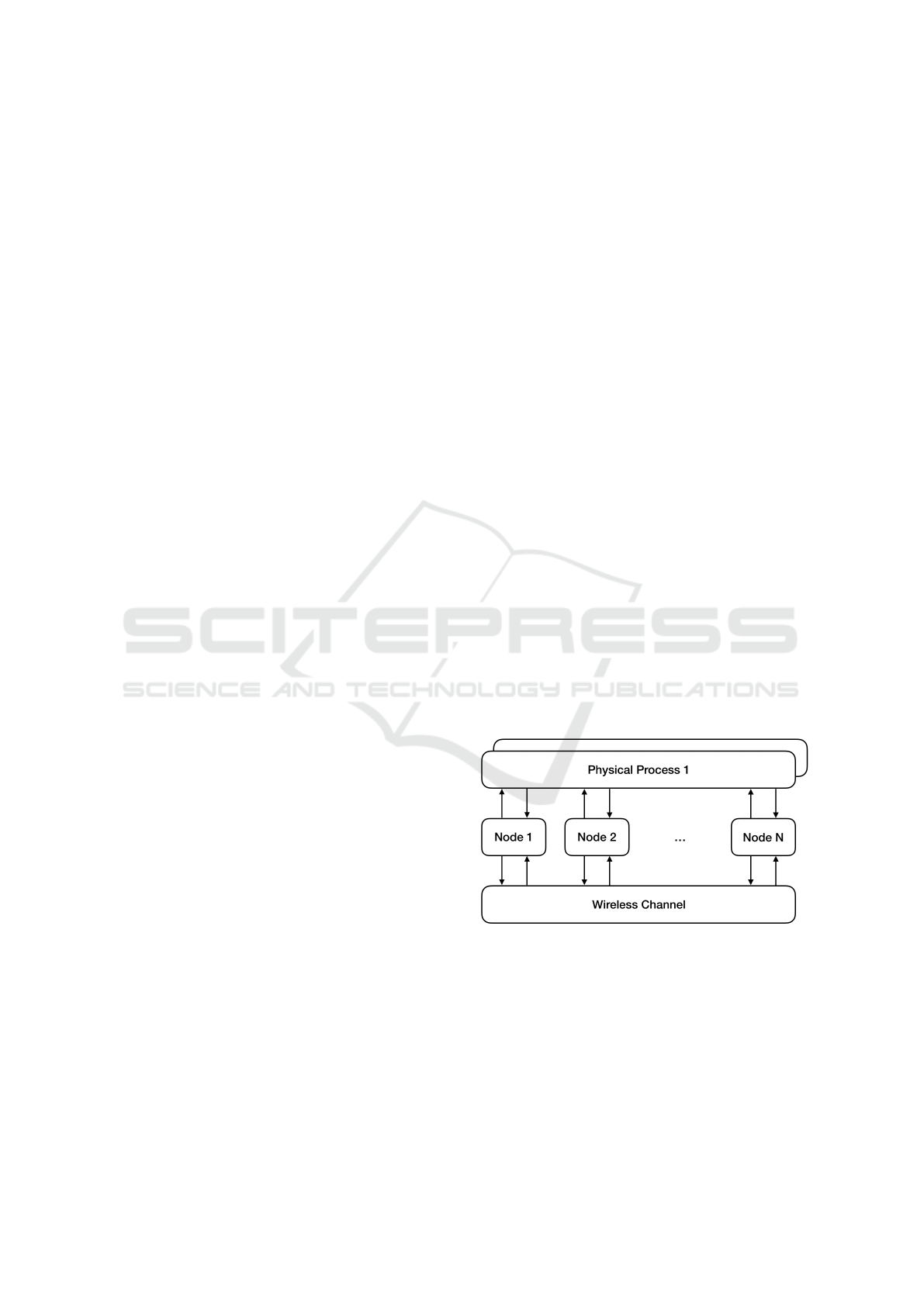
Figure 1: Generic Castalia network.
Castalia is an event-driven WSN simulator, built on
top of the popular OMNeT++ platform, which offers
wide support for building custom protocols and ap-
plications. OMNeT++ is based on two core concepts:
modules and messages (Varga, 2014). Simple mod-
ules represent the basic execution units, that execute
certain pieces of code when the related events occur.
Events are represented by messages, which are sent
(or scheduled) from one simple module to another,
ForSE 2020 - 4th International Workshop on FORmal methods for Security Engineering
816
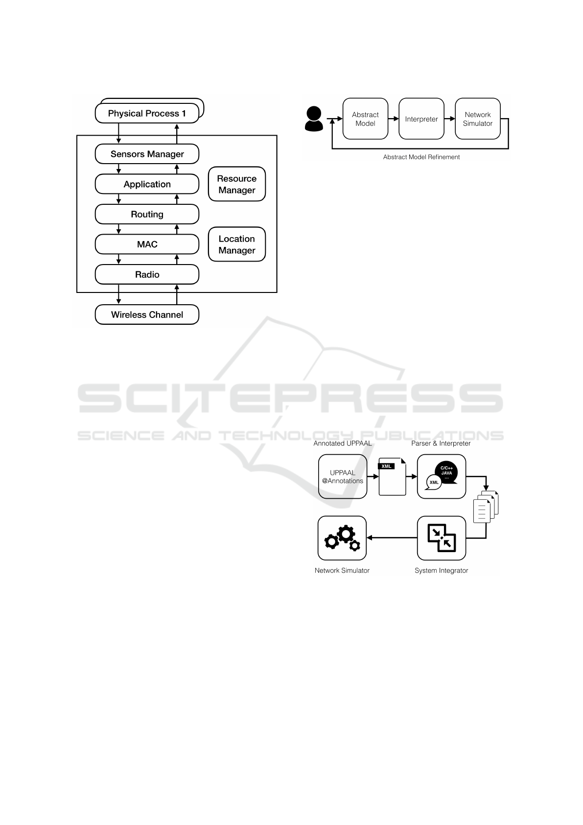
Figure 2: Generic Castalia node.
or itself. Simple modules, in turn, can be composed
together for building composite modules, to achieve
more complex functionalities.
Figure 1 shows the model of a generic Castalia
network, which is made by a set of composite mod-
ules, i.e. the nodes, the wireless channel and the phys-
ical processes monitored by nodes. Modules commu-
nicate with each other through message sending. The
arrows represent the flow of messages among mod-
ules. It is worth noting that nodes do not connect di-
rectly but through the wireless channel module.
Figure 2 shows the internal structure of the net-
work nodes. Each node is a composite module and
is built by the composition of a set of interconnected
simple modules. The entire communication stack is
modeled through simple modules. It is made up by
a Radio module linked with the Wireless Channel,
a MAC module, a Routing module and an Applica-
tion Module. Moreover, nodes are equipped with: i)
a Sensors Manager which is, in turn, linked with the
Physical Processes under monitoring; ii) a Mobility
Manager, that manages the position of the node over
time; and iii) a Resource Manager, for monitoring the
node’s resource consumption.
3 PROPOSED APPROACH
The approach we propose binds formal methods and
network simulators, as shown in Figure 3. First, WSN
designers can use formal methods to easily build an
Figure 3: WSN design and prototype approach.
abstract model of the protocol or application and
prove its general properties. Then, a more concrete
network model is generated starting from the abstract
model, via a dedicated Interpreter. Finally, such a
network model can be simulated through a network
simulator to gather realistic data that, in turn, can be
used for refining the initial abstract model. Such a
workflow can be repeated more times until both the
abstract and network models behave as expected.
In the following, we show the implementation of
such an approach, in which UPPAAL and Castalia
simulator are used as instances of the abstract model
checker and network simulator, respectively. Then,
we propose the design and prototype of a simple ap-
plication layer communication protocol through our
approach. Finally, we run simulations on the proto-
col model, both in attack free and attack scenarios, to
analyze its behavior and performance.
3.1 UPPAAL/Network Simulator
Integration Workflow
Figure 4: Workflow from UPPAAL to a generic network
simulator.
Figure 4 shows the workflow we propose for integrat-
ing UPPAAL with a generic network simulator.
As a first step, the UPPAAL model has to be en-
riched with information regarding the physical fea-
tures of the simulation environment, e.g. i) the size
of the simulation field; ii) the position of nodes in the
simulation field; iii) the latency of the channels; and
others. UPPAAL does not take into account the physi-
cal features at all, but network simulators require such
Analysis of Security Attacks in Wireless Sensor Networks: From UPPAAL to Castalia
817
information.
The enrichment of the UPPAAL model takes place
in the related XML file, precisely in the system tag,
using annotations, i.e. comments having the format:
//@<Annotation>. UPPAAL does not take into ac-
count such annotations at all since they are written as
comments in the UPPAAL code describing the sys-
tem. As an example, the following code shows the
annotation of the position of Node 1.
//@Position(20, 50, 10) node1 := relay(1);
In detail, the position of Node 1 is (x = 20, y = 50, z =
10) from the origin in a Cartesian coordinate system.
Then, as a second step, the XML file produced by
UPPAAL is parsed by the Parser for building a stan-
dard object-oriented model of the UPPAAL Timed
Automata.
Then, such an object-oriented model is inter-
preted, accordingly to the underlying network simu-
lator. As a result, the Interpreter produces a set of
files.
Furthermore, as a third step, the System Integrator
bundles the files produced by the Interpreter with the
vanilla Network Simulator.
Finally, as a fourth step, the Network Simulator
can simulate the UPPAAL model.
3.2 Application Model in UPPAAL
The applications running on network nodes are mod-
eled via parametric Automata, by exploiting the UP-
PAAL template system. Such Automata are paramet-
ric with respect to the node id. In general, leav-
ing out initialization and final states, network nodes
have only one main state from which a set of outgo-
ing transitions starts. Such transitions account for the
reception/transmission of packets from/to other net-
work nodes.
Moreover, network nodes are connected through
a non-blocking broadcast channel. It is worth not-
ing that the transmission of messages results in the
broadcast of them. Such a broadcast channel is
modeled through the global array chnl indexed by
the type node t, which defines the size of the ar-
ray itself. Similarly, we model the messages ex-
changed between network nodes through the global
array bmessages indexed by node t. Moreover, we
assume that each message is uniquely identified by its
timestamp. Therefore, we use the global declarations
that follow, where the variable NODES represents the
number of network nodes:
const int NODES = ...;
typedef int[0,NODES-1] node_t;
typedef int timestamp;
chan chnl[node_t]:
timestamp bmessages[node_t];
In the following, we refer to a WSN made up
of five nodes: i) one source node; and ii) four relay
nodes. The detailed model of such nodes is described
in Section 3.2.1.
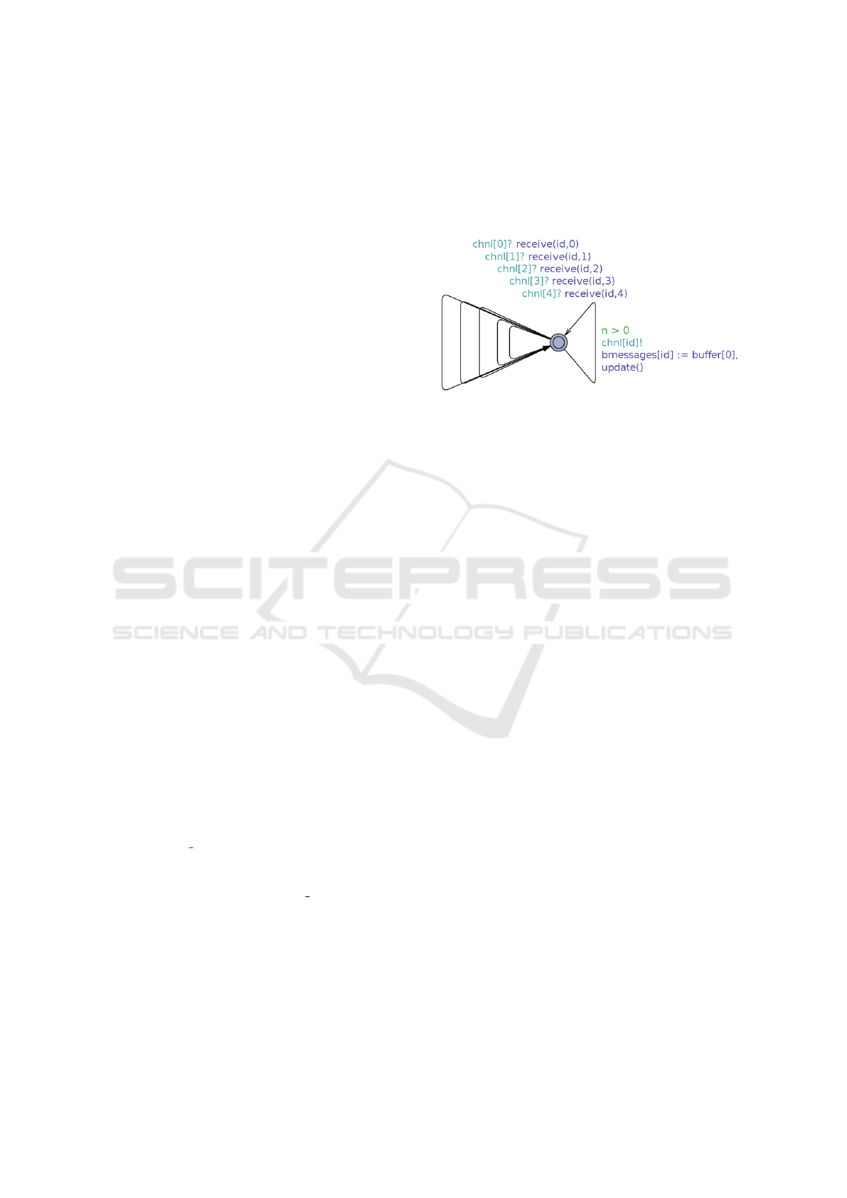
Figure 5: Abstract model of a generic relay node.
Figure 5 shows the template of the generic relay
node id. In detail, the model of relay nodes is made
by one location and six edges:
• five edges execute the input actions chnl[0]?
··· chnl[4];
• one edge executes the output action chnl[id]!.
The input action chnl[i]? is the action executed
by a node for receiving a message from the node i.
Similarly, the output action chnl[i]!bmessages[i]
represents the action executed by node i to broadcast
the message bmessages[i].
As depicted by Figure 5, the output action
chnl[id]! is enabled only if the global variable
bmessages[id] contains at least one message to
send, i.e. if n > 0. We point out that n represents
the number of messages to be forwarded, whereas
buffer[0] represents the messages stored in the head
of the local buffer of the node id, which is the FIFO
buffer that contains all the messages to be forwarded.
When a message is sent, it is stored into the global ar-
ray bmessages, i.e. bmessages[id] = buffer[0],
then the function update() is executed for updat-
ing node’s local data structures, as described in Sec-
tion 3.2.1.
Conversely, the input action chnl[i]? is always
enabled. However, messages broadcasted by node
i are received by node id only if nodes i and id
are neighbors. The function receive(id, i) imple-
ments the receiving of messages from neighbors, as
described in Section 3.2.1.
3.2.1 Flooding Protocol
Flooding (W. Heinzelman and Balakrishnan, 1999) is
a one-to-many routing protocol, in which a dedicated
node (the base station) needs to communicate general
ForSE 2020 - 4th International Workshop on FORmal methods for Security Engineering
818
information to all the nodes of the network. As an
example, flooding can be applied for dynamic route
discovery. A simple version of flooding behaves as
follows: whenever a network node receives a mes-
sage, it is forwarded to all its neighbors only if it has
not already been forwarded; otherwise, it is dropped.
Moreover, nodes drop old messages also, when re-
ceived. In the following, it is stated an interesting
property of the flooding protocol.
Property P: every node receives all the messages
sent by the base station, and every message that was
received is then forwarded only once.
Relay Nodes. Referring to the abstract model of a
generic relay node depicted in Figure 5, nodes are
provided with the local data structures that follow, in
order to support the flooding protocol.
const int MSGS = ...;
typedef int [0,MSGS-1] checker_t;
const int DIM = ...;
typedef in [0,DIM-1] size_t;
timestamp TS;
timestamp buffer[DIM];
int n;
timestamp logger[DIM];
int m;
MSGS represents the number of messages sent by the
base station; TS stores the most recent timestamp
of received messages; buffer is a FIFO buffer that
stores messages waiting to be forwarded; and, finally,
the buffer logger stores the already broadcasted mes-
sages. The latter buffer will be used to check the
Property P.
Moreover, for implementing the flooding algo-
rithm on relay nodes, the functions receive and
update of the timed automaton depicted in Figure 5
can be specialized as follows.
void receive(int j) {
if ( neighbor(id,j)
&& bmessages[j] > TS
&& n < DIM-1) ) {
buffer[n] = bmessages[j];
TS = bmessages[j];
n++;
}
}
void update() {
n--;
for( i : size_t ) {
buffer[i-1]=buffer[i];
}
if ( m < DIM-1 ) {
logger[m] = bmessages[id];
m++;
}
}
Where n and m represent the current number of el-
ements stored in buffer and logger, respectively.
In detail, the test bmessages[j] > TS in the func-
tion receive evaluates false when the node id re-
ceives either an old or an already received message.
In such cases, the received message is not stored into
buffer and is dropped. Moreover, after broadcasting
a message, the function update() executes a back-
ward one-position shift of buffer.
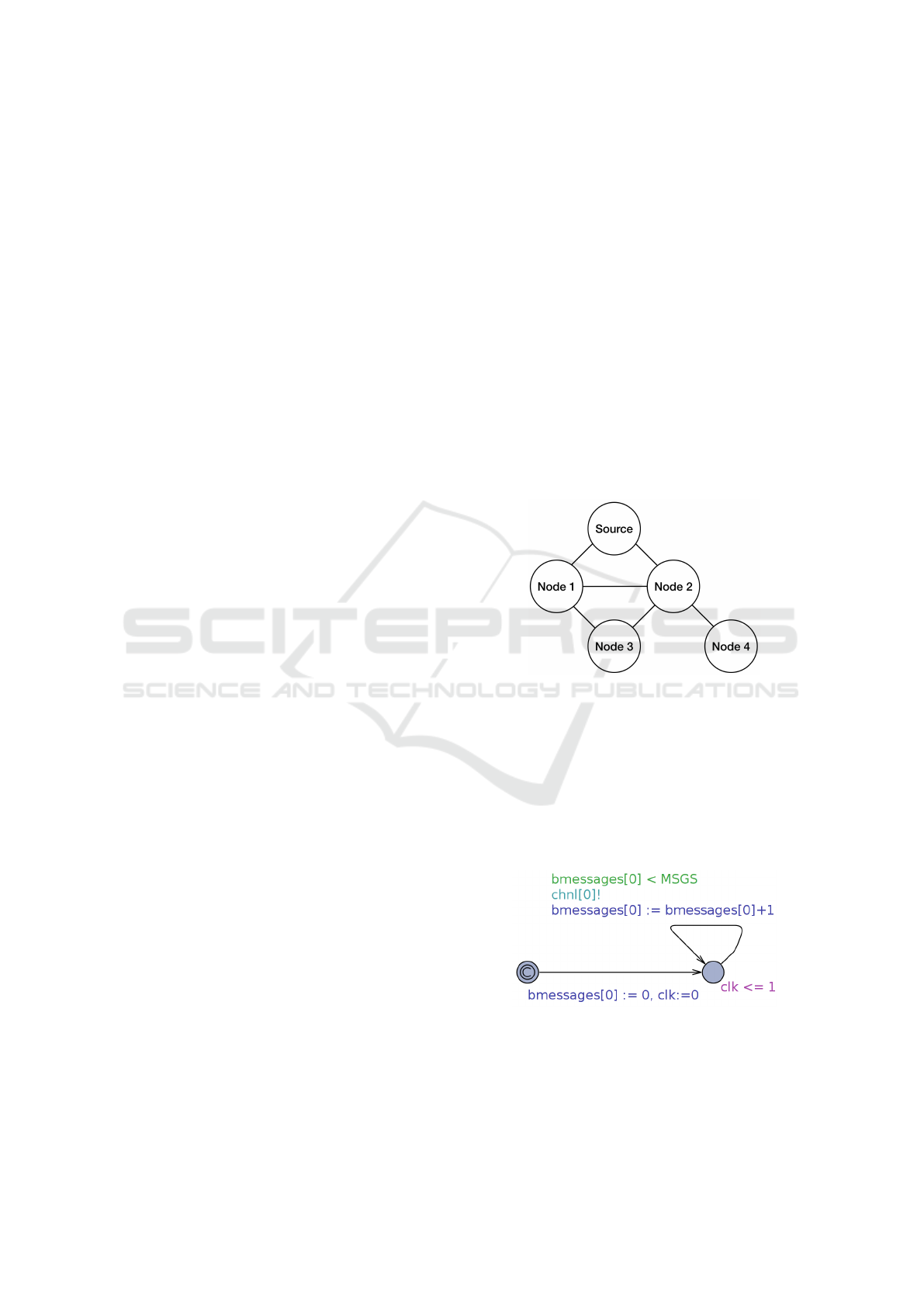
Figure 6 shows the network topology we con-
sider. Moreover, we assume the communication range
between nodes is one hop. As a consequence, the
function receive(id, i) of relay nodes is tailored
on such network parameters, and returns true if the
nodes id and i are one-hop neighbors, false other-
wise. As an example, receive(4, 2) returns true,
since Node 2 is a one-hop neighbor of Node 4. Con-
versely, receive(4, 3) returns false, since Node 3
is two-hops far away from Node 4.
Figure 6: Network topology.
Source Node. Figure 7 shows the UPPAAL tem-
plate that models the base station, named Source
node, of the flooding algorithm. The Source node
broadcasts a brand new message every clk units.
Messages sent by Source node are incrementally
timestamped, from 1 to MSGS, which is the last mes-
sage sent. After sending MSGS messages, the Source
node stops transmitting.
Figure 7: Abstract model of the Source node.
Network. According to the network topology (Fig-
ure 6), the UPPAAL network is specified as follows.
sourcenode := source();
node1 := relay(1);
Analysis of Security Attacks in Wireless Sensor Networks: From UPPAAL to Castalia
819
node2 := relay(2);
node3 := relay(3);
node4 := relay(4);
system sourcenode, node1, node2, node3, node4;
Where source and relay(id) represent the tem-
plates for the Source node and the Relay nodes, re-
spectively.
Then, the Property P of the flooding protocol,
which was previously described, can be checked via
UPPAAL by exploiting the formulas that follow.
A<>( forall ( i:checker_t )
node1.logger[i] == i + 1 )
A<>( forall ( i:checker_t )
node2.logger[i] == i + 1 )
A<>( forall ( i:checker_t )
node3.logger[i] == i + 1 )
A<>( forall ( i:checker_t )
node4.logger[i] == i + 1 )
In detail, we test the Property P against the content of
the buffer logger of all relay nodes. For each node,
the buffer logger stores all the messages forwarded
by it. Referring to the formulas above, logger[i]
represents the (i+1)-th message that was forwarded
by a certain node.
The Property P is proved to be true if, for each
relay node, for each i such as i ∈ [0, MSGS),
logger[i] stores the timestamp i+1. In this case,
all nodes forwarded only once all the messages they
received.
It is worth noting that UPPAAL tests the formu-
las above against all the possible execution paths of
the protocol. In particular, such formulas have been
proved to be true in our attack free simulation sce-
nario.
3.2.2 Modeling Attacks
Referring to the network topology shown in Figure 6,
we consider two attacks in both of which a node is
compromised by an adversary.
Drop Attack. In the first attack, at a random time,
the compromised node drops exactly one packet that,
instead, should have been sent to its neighbors. Fig-
ure 8 shows the model of the compromised node that
drops the packet.
Simulations done via UPPAAL show the results
that follow.
• when the adversary compromises Node 1, the
Property P described in 3.2.1 is still satisfied,
since Node 3 receives a copy of the dropped
packet from Node 2, thanks to link redundancy;
Figure 8: Template modeling the drop attack.
• when the adversary compromises Node 2, the
Property P is not satisfied anymore because Node
4 does not receive a copy of the dropped packet
since there is no redundancy on links connecting
Node 4 with other network nodes.
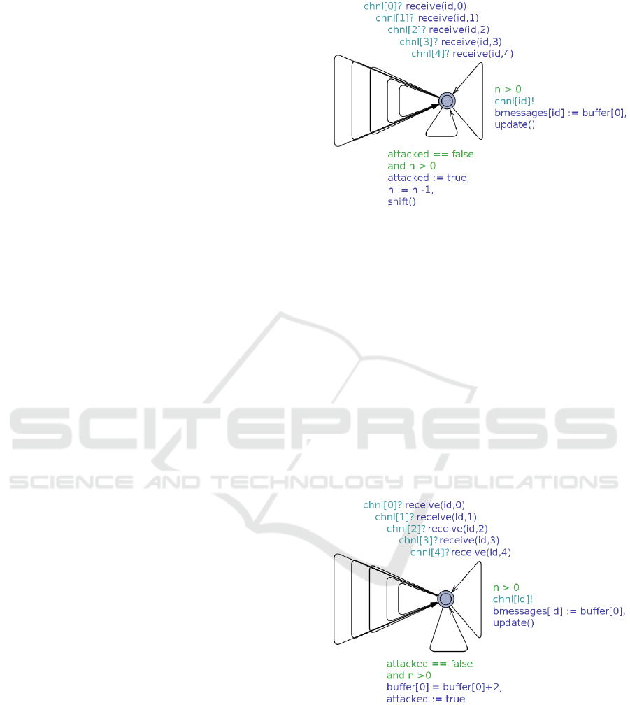
Tamper Attack. In the second attack, the compro-
mised node sends exactly one fake packet to its neigh-
bors. Such a packet contains a fake timestamp, which
is ahead in time compared to the current time. The
reception of the fake packet causes, on the recipient,
the discarding of all the genuine packets that carry a
timestamp older than the fake one. Figure 9 shows
the model of the compromised node that tampers the
packet.
Figure 9: Template modeling the tamper attack.
Simulations done via UPPAAL show the follow-
ing results.
• When the adversary compromises Node 1, the
Property P is not satisfied if Node 3 receives the
fake packet from Node 1 before the genuine pack-
ets carrying timestamps older than the fake one
from Node 2. Conversely, the Property P is satis-
fied if Node 3 receives from Node 2 all the gen-
ForSE 2020 - 4th International Workshop on FORmal methods for Security Engineering
820

uine packets carrying timestamps older than the
fake one before the fake packet from Node 1.
• When the adversary compromises Node 2, the
Property P is not satisfied anymore because Node
4, after receiving the fake packet, discards all the
subsequent genuine packets received from Node 4
that carry timestamps older than the fake one.
As shown in Figure 8 and Figure 9, both the at-
tacks are modeled by adding exactly one transition to
the model of the relay node shown in Figure 5. Both
attacks occur at random time and execute only once.
3.3 Implementation of the Integration
Framework
We have built an implementation of the framework
we propose. Such a prototype is built in Python and
integrates UPPAAL with Castalia, a C/C++ simula-
tor for WSNs. Castalia comes with a set of ready-
to-use components that cover the entire communica-
tion stack. Such components are fully tunable and
customizable and can be combined to each other to
implement nodes performing the desired behavior on
each layer of the communication stack. The prototype
we propose exploits such ready-to-use components.
In fact, it interprets the UPPAAL model for generat-
ing the application layer module from scratch. Then,
it combines the application layer module with other
ready-to-use modules implementing bottom layers.
The section that follows describes key design el-
ements of our prototype, which implements the inte-
gration framework from UPPAAL to Castalia.
3.3.1 UPPAAL Model Annotations
The prototype we present requires the user to annotate
the position of nodes only, since:
• it is the only parameter that cannot be automati-
cally inferred;
• the UPPAAL model involves the application layer
only, bottom layers are omitted;
• Castalia provides a set of ready-to-use Castalia
modules for implementing the whole communi-
cation stack;
• modules’ physical parameters of bottom layers
can be tuned after integration, also.
In the following, it is shown the tag system of the
enriched XML file related to the system topology de-
picted in Figure 6. Nodes are positioned accordingly
to Castalia’s coordinate reference system.
// @Position(10, 0, 0)
sourcenode := source();
// @Position(0, 10, 0)
node1 := relay(1);
// @Position(20, 10, 0)
node2 := relay(2);
// @Position(10, 20, 0)
node3 := relay(3);
// @Position(30, 20, 0)
node4 := relay(4);
system sourcenode, node1, node2, node3, node4;
3.3.2 Parser & Interpreter
The Parser parses the annotated XML file produced
by UPPAAL and builds an object-oriented model of
the Time Automata. Such an object-oriented model
is independent of the underlying Network Simulator.
Conversely, the Interpreter is strictly coupled with the
Network Simulator, since it produces the files that
will be bundled with it. In the following, we focus
on the files produced by Interpreter.
Network Configuration. The overall network con-
figuration is contained in the file omnetpp.ini,
which is extracted from the XML tag system. Such
a file defines the number of nodes, the positioning
of them, and the applications running on each layer
of their communication stacks. Moreover, it contains
all the network’s physical parameters, like the latency
of the channel, the transmission power of nodes’ an-
tennas, the nodes’ internal clock, and many others.
By tuning such parameters, it is possible to generate
several different configurations of the same network,
without re-building the Network Simulator.
Global Data Structures and Type Aliasing.
Global C/C++ headers containing global data struc-
tures and type aliasing are extracted from the global
XML tag declaration. Such data and types are
stored in the file UppaalGlobal.h, which will be im-
ported by all the classes using global data or types.
Application Layer Packet. The structure of the ap-
plication layer packet, used by all the network nodes,
is obtained from the definition of the UPPAAL com-
munication channel, which is contained in the text
of the global XML tag declaration. In detail, the
Interpreter stores the NED description of the packet
structure in the file UppaalPacket.msg. Such a
Analysis of Security Attacks in Wireless Sensor Networks: From UPPAAL to Castalia
821

file will be used during the build of the simula-
tor, for producing the files UppaalPacket m.h and
UppaalPacket m.cc, which contains the C++ model
of the packet itself. The header UppaalPacket m.h
will be imported by all the classes sending and re-
ceiving application layer packets.
Nodes’ Applications. The Interpreter produces one
application for each XML tag template. Each node
of the network runs a certain application, namely tem-
plate, in its application layer simple module. From an
overall point of view, an application is made by:
• one NED description of the simple module exe-
cuting the application;
• a set of C/C++ files implementing the application
itself.
In detail, each application is provided with a Fi-
nite State Machine (FSM), that implements the be-
havior described by the XML template. Referring to
the content of the XML tag template:
• each location accounts for one FSM’ state;
• each transition accounts for one FSM’s transi-
tion.
Moreover, the application is provided with the
FSM’s transition map, used to let the FSM evolve.
All of FMS’s transitions implements the following ab-
stract functions:
bool
AbstractTransition::checkGuard();
bool
AbstractTransition::doSynchronization();
std::string
AbstractTransition::doAssignments();
The functions checkGuard, doSynchronization,
and doAssignments implement the UPPAAL tran-
sition’s guard, synchronization and assignments, re-
spectively.
The FSM evolves according to the node’s clock,
through the execution of transitions, namely perform-
ing the UPPAAL transition’s assignments. At each
clock tick, the application retrieves all the outgoing
transitions for the current node from the FSM transi-
tion map. Then, it executes the transition that satisfies
both the guard and the synchronization conditions. If
no transition is possible, the FSM does not evolve in
the current clock frame. Conversely, if more transi-
tions can be performed, the application executes one
of them randomly.
Nodes Synchronization. In Castalia, nodes asyn-
chronously communicate with each other. Moreover,
when transmitting, nodes broadcast packets. UP-
PAAL transmission and reception synchronizations
are supported in Castalia in two different ways.
Transitions containing a transmission synchro-
nization can be always executed if the related guard
is satisfied. A UPPAAL transmission synchroniza-
tion, for example on channel 0, i.e. message[0]!, re-
sults in the broadcast of a UppaalApplication packet,
as shown in the following code:
UppaalPacket* uppaalPacket;
uppaalPacekt = new UppaalPacket(nodeid);
toNewtorkLayer(uppaalPacket, BROADCAST);
After the packet is broadcasted, it is received by
all nodes positioned inside the sender’s transmission
range.
To support the UPPAAL reception synchroniza-
tion, each node is provided with a reception buffer on
the application layer. Such a buffer follows the FIFO
policy. Nodes store UppaalPackets into the reception
buffer as soon as they are received.
Then, when a reception transition is executed, for
example on channel 0, i.e. message[0]?, it results in
the scanning of the reception buffer, looking for the
first UppaalPacket received from Node 0. If the target
UppaalPacket is found, then the transition is executed.
Otherwise, the FSM does not evolve in the current
clock frame.
3.3.3 Integration and Run
The System Integrator bundles the files produced by
the Interpreter with Castalia, then builds the simula-
tor. When the build ends, the UPPAAL model can be
simulated on Castalia. It is worth noting that Castalia
makes it possible to have several different configura-
tions for the same WSN, without re-build the simula-
tor.
Then, a certain WSN model may have several dif-
ferent configurations that differ from each other due
to: i) the positioning of the nodes; ii) the latency of the
channel; iii) the bottom layers protocols; iv) or other
tuning parameters. Batch processing can be used for
simulating a large number of different configurations
for a certain WSN model, with the aim of validating
a large number of different scenarios through simula-
tion.
In the following, it is shown a sample of a simula-
tion report provided by Castalia, when simulating the
attack free scenario. In detail, it lists the packets re-
ceived by Node 4 during a simulation run. The clock
period of all nodes is 100 ms.
ForSE 2020 - 4th International Workshop on FORmal methods for Security Engineering
822
...
Node4> at time 1.59 sec received value 1
from node 2
Node4> at time 1.69 sec received value 2
from node 2
Node4> at time 1.79 sec received value 3
from node 2
...
In the attack free scenario, Node 4 receives all the
packets sent by the Source node, through Node 2,
without repeated messages coming from the same
node.
Conversely, when compromising Node 2 for exe-
cuting the drop attack, we obtain the result that fol-
lows.
...
Node4> at time 2.05 sec received value 6
from node 2
Node4> at time 2.25 sec received value 8
from node 2
Node4> at time 2.35 sec received value 9
from node 2
...
In this case, when the attack occurs, Node 4 does not
receive packet 7 from Node 2, according to the results
provided by UPPAAL.
Similarly, when compromising Node 2 for execut-
ing the tamper attack, we obtain the result that fol-
lows.
...
Node4> at time 2.83 sec received value 14
from node 2
Node4> at time 3.13 sec received value 17
from node 2
Node4> at time 3.23 sec received value 18
from node 2
...
In this case, when the attack occurs, Node 4 does not
receive packets 15 and 16 from Node 2.
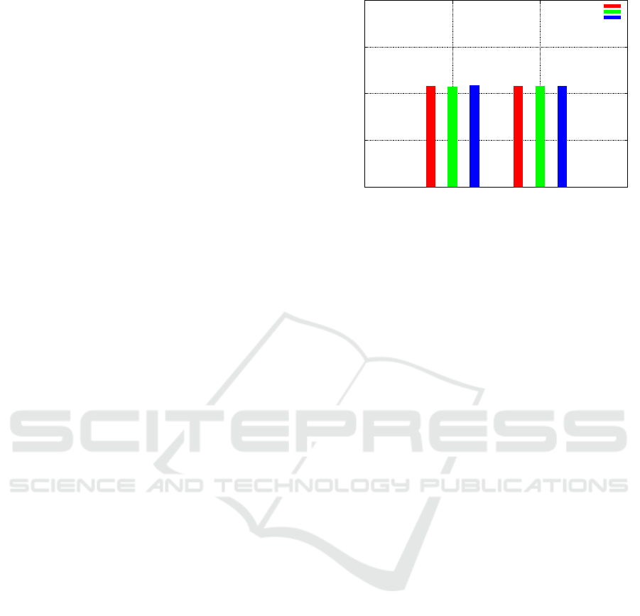
Moreover, it is possible to obtain several physi-
cal measurements from Castalia. As an example, Fig-
ure 10 shows the energy consumption of Node 2 and
Node 4 in all the three scenarios, namely attack free
scenario, drop attack scenario and tamper attack sce-
nario. For each scenario, the energy consumption is
obtained as a weighted average of ten simulation runs.
As expected, power consumption among the three
scenarios is nearly unchanged (about 8 mJ), since at-
tacks execute only once and result, at most, in avoid-
ing only one packet transmission on Node 2 (drop
attack). However, power consumption can signifi-
cantly vary in other scenarios such as attacks in which
malicious nodes specifically act for draining network
nodes’ batteries (Eugene Y. Vasserman, 2013).
7
7.5
8
8.5
9
Node2 Node4
Energy consumed (mJ)
Nodes
No Attack
Drop Attack
Tamper Attack
Figure 10: Measurement of energy consumed by Node 2
and Node 4.
4 CONCLUSIONS
This paper presents ongoing work on a security-aware
design approach for WSN applications and protocols.
Such an approach exploits the integration between
formal methods and network simulators, for provid-
ing WSN designers with a toolchain that makes it
possible to easily model and rapidly prototype WSN
protocols and applications, and then simulate them
on several different scenarios, including security at-
tack scenarios. This enables WSN designers to gather
valuable insights on the realistic behavior of the ab-
stract model since from design time, such as energy
consumption and computational speed, thus helping
them to recognize design flaws and security-related
issues, and then select appropriate solutions.
To support our points, we have built a tool that in-
tegrates the model checker UPPAAL with the WSNs
simulator Castalia. Such a tool makes it possible
to automatically generate a Castalia network model
starting from a UPPAAL abstract model. Then, we
have designed an application-level flooding protocol
through UPPAAL and we have produced the related
network model using our tool. After that, we have
executed simulations of such a flooding protocol both
on attack free and attack scenarios. Finally, simula-
tion results have been used both to validate the ini-
tial model and to analyze the battery consumption of
nodes running the flooding protocol both in attack
free and attack scenarios.
In our future work, we will analyze several at-
tack scenarios and, for each of them, we will show
how the insights provided by the network simulator
can be effectively used for selecting effective coun-
termeasures and, consequently, for refining the initial
abstract model.
Analysis of Security Attacks in Wireless Sensor Networks: From UPPAAL to Castalia
823

ACKNOWLEDGEMENTS
This research was partially supported by the Italian
Ministry of Education and Research (MIUR) in the
framework of the CrossLab project (Departments of
Excellence), and by the PRA 2018 81 project entitled
“Wearable sensor systems: personalized analysis and
data security in healthcare” funded by the University
of Pisa.
REFERENCES
A. Boulis, D. P. (2013). Castalia - A simula-
tor for Wireless Sensor Networks and Body
Area Networks, version 3.3, User’s Manual.
https://github.com/boulis/Castalia/blob/master/
Castalia.
Alur, R. and Dill, D. L. (1994). A theory of timed automata.
Theoretical Computer Science, 126(2):183–235.
Behrmann, G., David, A., and Larsen, K. G.
(2006). A Tutorial on UPPAAL 4.0.
http://www.it.uu.se/research/group/darts/papers/texts/
new-tutorial.pdf.
Bernardeschi, C., Domenici, A., and Masci, P. (2018). A
pvs-simulink integrated environment for model-based
analysis of cyber-physical systems. IEEE Trans. Soft-
ware Eng., 44(6):512–533.
Bernardeschi, C., Masci, P., and Pfeifer, H. (2008). Early
prototyping of wireless sensor network algorithms in
PVS. In Computer Safety, Reliability, and Security,
27th International Conference, SAFECOMP 2008,
Newcastle upon Tyne, UK, September 22-25, 2008,
Proceedings, pages 346–359.
Bernardeschi, C., Masci, P., and Pfeifer, H. (2009). Anal-
ysis of wireless sensor network protocols in dynamic
scenarios. In Stabilization, Safety, and Security of Dis-
tributed Systems, 11th International Symposium, SSS
2009, Lyon, France, November 3-6, 2009. Proceed-
ings, pages 105–119.
Bolton, C. and Lowe, G. (2004). Analyses of the re-
verse path forwarding routing algorithm. In Intl. Conf.
on Dependable Systems and Networks Proceedings,
pages 485–494. IEEE Computer Society.
Cardenas, A. A., Roosta, T., and Sastry, S. (2009). Re-
thinking security properties, threat models, and the de-
sign space in sensor networks: A case study in scada
systems. Ad Hoc Networks, 7(8):1434 – 1447. Pri-
vacy and Security in Wireless Sensor and Ad Hoc Net-
works.
Eugene Y. Vasserman, N. H. (2013). Vampire attacks:
Draining life from wireless ad hoc sensor networks.
IEEE Transactions on Mobile Computing, 12(2):318
– 332.
J. Buck, S. Ha, E. A. L. and Messerschmitt, D. G. (1994).
Ptolemy: a framework for simulating and prototyp-
ing heterogeneous systems. Int. Journal of Computer
Simulation, 4:155–182.
K. Bhargavan, C. Gunter, I. L. O. S. M. K. D. O. and
Viswanathan, M. (2002). Verisim: Formal analysis
of network simulations. IEEE Trans. Software Engi-
neering, 28(2):129–145.
Lazarescu, M. T. and Lavagno, L. (2017). Wireless Sen-
sor Networks, pages 1–42. Springer Netherlands, Dor-
drecht.
Nair, S. and Cardell-Oliver, R. (2004). Formal specifica-
tion and analysis of performance variation in sensor
network diffusion protocols. In Symp. on Modeling,
Analysis and Simulation of Wireless and Mobile Sys-
tems Proceedings, pages 170–173. ACM.
Palmieri, M., Bernardeschi, C., and Masci, P. (2019).
A framework for fmi-based co-simulation of hu-
man–machine interfaces. Softw Syst Model.
Tom Henderson, George Riley, S. F. and Sumit Roy, e. a.
(2019). The NS Manual.
Varga, A. (2014). OMNeT++. https://doc.omnetpp.org/
omnetpp4/manual.
W. Heinzelman, J. K. and Balakrishnan, H. (1999). Adap-
tive protocols for information dissemination in wire-
less sensor networks. In Proc. Intl. Conf. on Mobile
Computing and Networking, pages 174–185. ACM.
ForSE 2020 - 4th International Workshop on FORmal methods for Security Engineering
824
