
Unity 3D Simulator of Autonomous Motorway Traffic Applied to
Emergency Corridor Building
Jurij Kuzmic
and Günter Rudolph
Department of Computer Science, TU Dortmund University, Otto-Hahn-Str. 14, Dortmund, Germany
Keywords: Simulator in Unity 3D, Emergency Corridor Simulation on Motorways, Accident Simulation, Autonomous
Driving, Vehicle-to-Vehicle (V2V) Communication, Lane Detection, Distance Detection, Rotation Detection.
Abstract: This paper introduces a 3D simulator made with the game engine Unity to analyse the behaviour of
autonomous vehicles in the case of unexpected accidents in motorway traffic. This simulator works towards
the removal of current problems with building an emergency corridor on motorways. It is often the case that
rescue vehicles cannot reach the scene of an accident and are obstructed by other road users. This means that
the help for those involved in the accident may come too late. To prevent this in future with autonomous
vehicles and to save human lives, building an emergency corridor for self-driving cars will be simulated and
presented with the game engine Unity. Since the autonomous vehicles also have to communicate while driving,
the techniques of Vehicle-to-Infrastructure (V2I) Communication, Vehicle-to-Vehicle (V2V) Communication
and Infrastructure-to-Infrastructure (I2I) Communication will be reviewed theoretically. Besides, practical
methods for lane, distance and rotation detection will be presented. Furthermore, we discuss sensor
technology such as position estimator, lidar, radar and video camera. Also, the levels of automation of self-
driving cars will be shown. This will make it possible to determine the level of the automated rescue corridor
formation. Several experiments prove the simulator’s functionality concerning unexpected accidents and the
formation of the rescue corridor. Finally, further research and work in this area will be explained briefly.
1 INTRODUCTION
The autonomous vehicles industry is trying to
improve the safety and therefore to reduce the
accidents caused by autonomous vehicles as much as
possible. Nevertheless, accidents could be due to
technical defects or unexpected software errors. In
order to map the behaviour of unexpected accidents
with autonomous vehicles, a simulator has been
implemented with Unity 3D. Before starting the
implementation of the simulator, an established
traffic flow simulator has been searched. Some
simulators are available: PTV Vissim (PTVGroup,
2019), MATSim (MATSim, 2019), SUMO
(Behrisch, Bieker, Erdmann and Krajzewicz, 2011),
MAINSIM (Dallmeyer and Timm, 2012).
Unfortunately, the behaviour of the car cannot be
freely programmed. In addition, the position of the
car cannot be freely changed. This is the reason why
an own simulator has been implemented with Unity.
This allows to affect the behaviours of the car, the
communication between vehicles and the detection of
the lane, distance, rotation and accident in relation to
a traffic flow simulator. The motorway can also be
freely designed. For instance, several lanes can be
added, which can vary in width.
There are already several projects in Unity that
deal with the simulation of autonomous vehicles. For
example, roads with cars, pedestrians and
autonomous vehicles with sensors can be created (De
Oliveira, 2018). Some projects even include self-
driving cars with image recognition of the simulated
environment (De Oliveira and Duong, 2018). We
wanted to simulate the building of the rescue corridor
with autonomous vehicles on motorways, among
other things. So we needed the ability to create
motorways with crash barriers and multiple lanes. For
this reason, we implemented our own simulator. To
the best of our knowledge, there is still no published
research in the field of building an emergency
corridor with autonomous vehicles automatically.
Kuzmic, J. and Rudolph, G.
Unity 3D Simulator of Autonomous Motorway Traffic Applied to Emergency Corridor Building.
DOI: 10.5220/0009349601970204
In Proceedings of the 5th International Conference on Internet of Things, Big Data and Security (IoTBDS 2020), pages 197-204
ISBN: 978-989-758-426-8
Copyright
c
2020 by SCITEPRESS – Science and Technology Publications, Lda. All rights reserved
197

2 AUTONOMOUS VEHICLES IN
PRACTICE
In order, to implement a suitable simulator for
unexpected accident simulations with autonomous
vehicles on motorways, the technology of
autonomous vehicles was examined focusing on
practical applications.
2.1 Lane, Distance and Rotation
Detection
This section discusses briefly the lane detection, the
distance detection, the rotation detection and the used
sensors in practice. Usually, the detection of lane or
keeping the vehicle on track is carried out by image
recognition via the video camera. Usually, this is
installed in the front windshield. The perception of
the urban environment is done by a rotatable sensor
called lidar on the roof of the vehicle. Thereby 3D
mapping (3D environment) can be created. The
distance sensors (radar) are necessary for automatic
parking and getting the distance to the front vehicle.
The position estimator is required for the vehicle’s
rotation detection and the determination of the
position of the vehicle (Azmat and Schuhmayer,
2015).
2.2 Communication between
Self-driving Cars
In practice, communication between autonomous
vehicles is often divided into three communication
options. The first is Vehicle-to-Infrastructure (V2I)
Communication. For example, this allows to transmit
the current colour of the traffic light to the arriving
vehicle. The second option is Vehicle-to-Vehicle
(V2V) Communication. In this way, an accident
vehicle can notify the other vehicles in the urban area.
The third is Infrastructure-to-Infrastructure (I2I)
Communication. I2I Communication can be used to
switch traffic light systems intelligently to avoid
traffic jams. To enable communication, a vehicular
ad-hoc network (VANet) is set up (Hartenstein and
Laberteaux, 2008). This is a mobile ad-hoc network
(MANet), whose nodes for message distribution are
the vehicles themselves. These vehicles have On-
Board Units (OBUs) that are responsible for
communication between the vehicles and road-side
units (RSUs) (Alheeti, Gruebler, McDonald-Maier,
2016).
2.3 Levels of Automation
This section surveys the levels of automation for the
autonomous vehicle. These are divided into five
levels. The classification of the level depends on the
technologies used in the vehicle and the driver’s
intervention in the driving process (Urooj, Feroz and
Ahmad, 2018). The following table 1 describes these
levels.
Table 1: Levels of automation (NHTSA) (Leftlaneadvisors,
2013).
Level Automation
Level 0
No vehicle autonomy,
Driver has Control
Level 1
Vehicle provides driver info/warnings,
Driver has informed control
Level 2
Vehicle integrates detection/response,
Driver ready to take control
Level 3
Vehicle fully autonomous,
Driver takes control in emergency
Level 4a
Vehicle fully autonomous,
Occupants do not need ability to drive
Level 4b
Vehicle connected and cooperating,
Optimised System operation and passive
driver experience
The self-driving car could build an emergency
corridor automatically after the third level of
automation. From this level, the vehicle is completely
autonomous. The driver only takes part in the driving
process in dangerous situations.
3 SIMULATION IN UNITY 3D
Based on how the autonomous vehicles work in
practice, the requirements for a suitable
implementation of the simulator could be derived. To
ease the implementation effort, the asset “Car'Toon :
The Sport Car with interior” was retrieved from the
Unity Asset Store (Unity Asset Store, 2019). It
already contains the implementation of the steering
behaviour, acceleration, braking and physics of a car.
So the car could be successfully used in our project.
During the implementation of the automated
emergency corridor formation, it was noticeable that
the car could not be steered during emergency
braking because the wheels of the car from this
example completely block during braking with all
four wheels. In order to be able to build an emergency
corridor, it is not only necessary to brake during
emergency braking, but also to steer. In practice, this
is only possible with Anti-lock Braking System
(ABS).
IoTBDS 2020 - 5th International Conference on Internet of Things, Big Data and Security
198
As a result, this was also implemented in this
simulator by hand. In a dangerous situation, a human
cannot brake and think about building an emergency
corridor at the same time. For comparison, the
autonomous vehicle is able to do this, because it does
not react nervously and hectically towards the human.
3.1 Lane, Distance and Rotation
Detection
This section deals with the detection of the lane, the
detection of the distance to the following vehicle and
the detection of the rotation of the car in the presented
simulator. For simplicity, the detection of the lane
was implemented in a different way than known from
practice (image recognition with video camera). Ray
casts from Unity were used to determine the width of
the lane to keep the vehicle on track. This replaces the
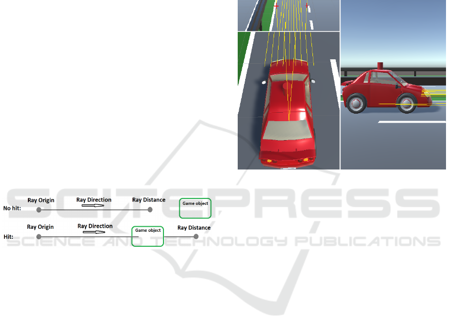
image recognition with a video camera. Ray casts can
be imagined as a line in a certain direction with a
certain length.
As soon as a game object is hit by this line, it also
provides the name and distance to this object in a
three-dimensional space. This allows to determine the
object which has been hit and how far it is from the
ray origin (Fig. 1).
Figure 1: No hit/hit ray cast example.
For the detection of the lane, two ray casts were used
(Fig. 2, left-top). Both are directed from the vehicle
to the front and they slightly look downwards (Fig. 2,
left-bottom). Ray casts can be used to simulate not
only lane detection, but also distance sensors (radar).
In practice, radar determines the distance to the front
vehicle. The various practical sensors are described
more detailed in section 2. The nine forward ray casts,
shown in figure 2, are necessary to determine the
distance to the following vehicle. As soon as the
distance can be measured, a function calculates the
safety distance to the following vehicle on the base of
the driving speed.
The implemented rotation detection of the own
vehicle includes the monitoring of the rotation per
frame. This implementation simulates the sensor for
the position estimation from practice. As soon as a
large rotation has taken place in a short time, an
unexpected rotation of the vehicle can be assumed.
This rotation detection helps to simulate the bursting
of a tire while driving. More about this experiment
can be found in section 4. In addition to the rotation,
the collision of the vehicle is also monitored. This
method is provided by Unity and is automatically
called when a game object collides with another game
object. As soon as one of these two accidents is
detected, the self-driving car makes an emergency
stop, switches on the indicator warning lights and
notifies the self-driving cars in the area. This scenario
is explained in more detail in the next subsection.
Figure 2: Ray casts of a self-driving car for lane and
distance detection. Left-top: Ray casts for lane detection.
Left-bottom: Top-view of a car. Right: Side-view of a car.
Based on own experiments, an effective function (Eq.
1) for the braking distance could be found for this
simulation. This function provides the braking
distance (bd) based on the vehicle's driving speed (s).
However, this is only the braking distance, which has
to be kept in any case. In our used function (Eq. 2), a
linear value (d) for the safety distance (sd) was added
to the braking distance (bd).
0.00004
0.0135
0.0601
0.02219
(1)
(2)
Other models are imaginable and will be tested in
future.
3.2 Communication between
Self-driving Cars
Communication between autonomous vehicles is
very important. This exchange of messages between
autonomous vehicles is like a warning by flashing
indicator warning lights or brake lights for humans. It
is also important that the communication takes place
from vehicle to vehicle. This means that the
communication works without a central point, such as
Unity 3D Simulator of Autonomous Motorway Traffic Applied to Emergency Corridor Building
199
a pole. This can fail or be manipulated. The
coordination of the self-driving cars can also be
realized by the communication. As an example, all
vehicles stop unexpectedly. That raises the questions:
Who has to do something first? Here it is also difficult
to map the rules. How do vehicles behave in the event
of an accident, for example, due to a technical defect?
Who drives by? Who stops? Even for a human, in
some situations it is difficult to decide how to behave
correctly.
Communication can also be used to find out the
lane position of the vehicle and the number of lanes
of the motorway in total. The autonomous vehicles
can independently recognize the environment and
communicate this to the next autonomous vehicles.
Through unique identification numbers (IDs), the
vehicles know which vehicle is in front, behind, left
and right. As soon as an accident is detected, this has
also to be passed on to the following vehicles. As
soon as a message arrives, the lidar on the roof of the
vehicle turns yellow, which is still currently under
construction in this paper. This colouring makes the
arrival of the messages visible for the human eye.
Communication between agents can be implemented
with Unity in two different ways. Both approaches
have been tested for communication between
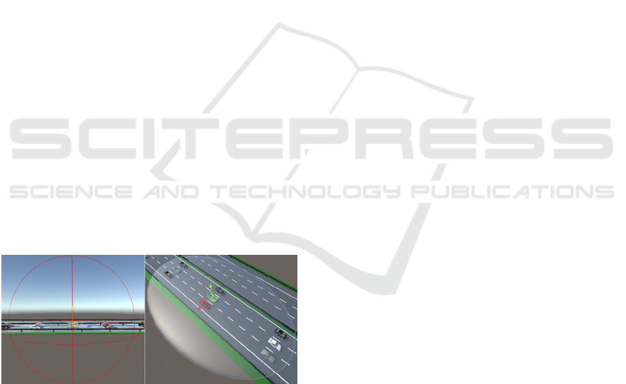
vehicles. The first approach utilises a sphere given a
centre point and a radius. All objects inside this
sphere can be located. This allows to quickly
determine which vehicles are nearby. At this point,
the own vehicle is also delivered. This has of course
to be ignored in this case. Figure 3, left shows the
sphere in use. The centre of this sphere was placed at
the centre of the autonomous vehicle.
Figure 3: Communication between agents. Left:
Communication with sphere. Right: Communication with
ellipse.
In the previous figure 3, left can also be seen, that the
sphere recognises the objects above and below the
vehicle. Sending the messages above or below is not
necessary in this case. This does not correspond to
reality. In practice, the signal would not be wasted
upwards or downwards. This would be a signal in a
certain direction by directional antennas. This allows
reaching larger distances with the same transmission
power. For this reason, a separate ellipse was
implemented. The figure 3, right shows this ellipse
graphically. In this case, the communication ellipse is
a game object that is located in the vehicle as a sub
game object. This contains methods to trigger the
objects and a dictionary with the collided game
objects. These collisions are called haptic and not
physical collisions. The methods are called
automatically if a collision occurs or leaves. This
happens in the background, so the dictionary with the
collided vehicles is always up to date.
As soon as an accident is detected, the vehicle
performs an emergency stop, switches on the
indicator warning lights and inform the vehicles in the
surrounding area. The vehicles that receive the
message, decide on their own how to react to this
message. The direction and the position of the
vehicles are compared. Only the vehicles that are
moving in the same direction and are behind the
accident vehicle slow down and forward this message
to the rear vehicles. The other vehicles that are nearby
and do not have to brake, as there is no danger for
these vehicles, accept the message and inform the
emergency services. The experiments show that the
detection of the vehicles in the surrounding area with
the ellipse as a sub game object works faster. Thus,
the messages can be transmitted faster to the vehicles
in the surrounding area. The reason for this, the haptic
collision detection of collided vehicles in the
surrounding area is located in the background and is
always up to date at any time of the program. With
the sphere, on the other hand, the vehicles in the
surrounding area are calculated each time the
messages are sent. With many messages per vehicle,
this of course takes more time. A message controller
class has been implemented to control the incoming
and outgoing messages. This is necessary for the
storage of the messages. A message contains the
following information: transmitter id, outgoing
message, receiver id, incoming message, message
enter time, accident car drive direction and accident
car position. Currently can be responded to the
outgoing message like “SPIN”, “ACCIDENT” and
“FORWARD”. The stored messages are always kept
up to date. Each time a message is received, the
current incoming data is updated. The vehicles, that
decide the message is not relevant, for themselves
save the message and contact rescue.
IoTBDS 2020 - 5th International Conference on Internet of Things, Big Data and Security
200
4 EXPERIMENTS
The following experiments were carried out to control
the functionality of the simulator. In the event of an
accident, the formation of the rescue corridor is very
important. Unforeseeable accidents happen again and
again on roads and motorways. Serious accidents can
sometimes occur on motorways because vehicles
move at high speed. This leads to traffic jams and
road closures. In this case, there is a regulation for the
formation of an emergency corridor for the
emergency vehicles arriving at the scene of the
accident. However, unfortunately this is just the
theory. The drivers of motor vehicles sometimes
forget to form a rescue corridor in a traffic jam. In
some cases, it is no longer possible to build an
emergency corridor at a later point of time. When the
vehicles come to stand, they are usually too close to
each other. In addition, due to the daily commute to
work on the motorway, it is also noticeable that even
if a rescue corridor is formed and an emergency
vehicle drives past, the drivers of the motor vehicles
close this emergency corridor again. This always
leads to obstruction of the rescue vehicle. The
problem is already known and has been discussed for
some time (Dębiński, Jukowski and Bohatkiewicz,
2018). This does not only occur on motorways, but
also in cities. There is currently no optimal solution
for this problem. Some countries impose heavy fines
for the obstruction of emergency vehicles. To
counteract this problem, a warning system for an
emergency vehicle (Emergency Vehicle Warning
System) has already been introduced (Buchenscheit,
Schaub, Kargl and Weber, 2010). To solve this
problem, the emergency corridor has to be formed
automatically by the self-driving cars that will soon
be on the roads. The question is not whether, but when
the autonomous vehicles will come onto our roads.
For building an emergency corridor with
autonomous vehicles in the presented simulator, it is
necessary to know on which lane the vehicle is
currently located and how many lanes the motorway
has in total. For example, on a motorway with two
lanes or more, the vehicles on the left lane drive even
more left to the crash barrier. On the other hand, the
vehicles on the right lane drive more to the right onto
the lane marking. The ray casts are accessed again to
compare the position of the left and right front wheel
with the lane markings. This can be used to determine
in which direction (left or right) the car has to move
to build an emergency corridor. As soon as the speed
falls below a certain value, the vehicles automatically
form a rescue corridor. This means that an emergency
corridor is always build in the event of slow-moving
traffic or traffic jams. This can be seen in the figures
in section 4.1.
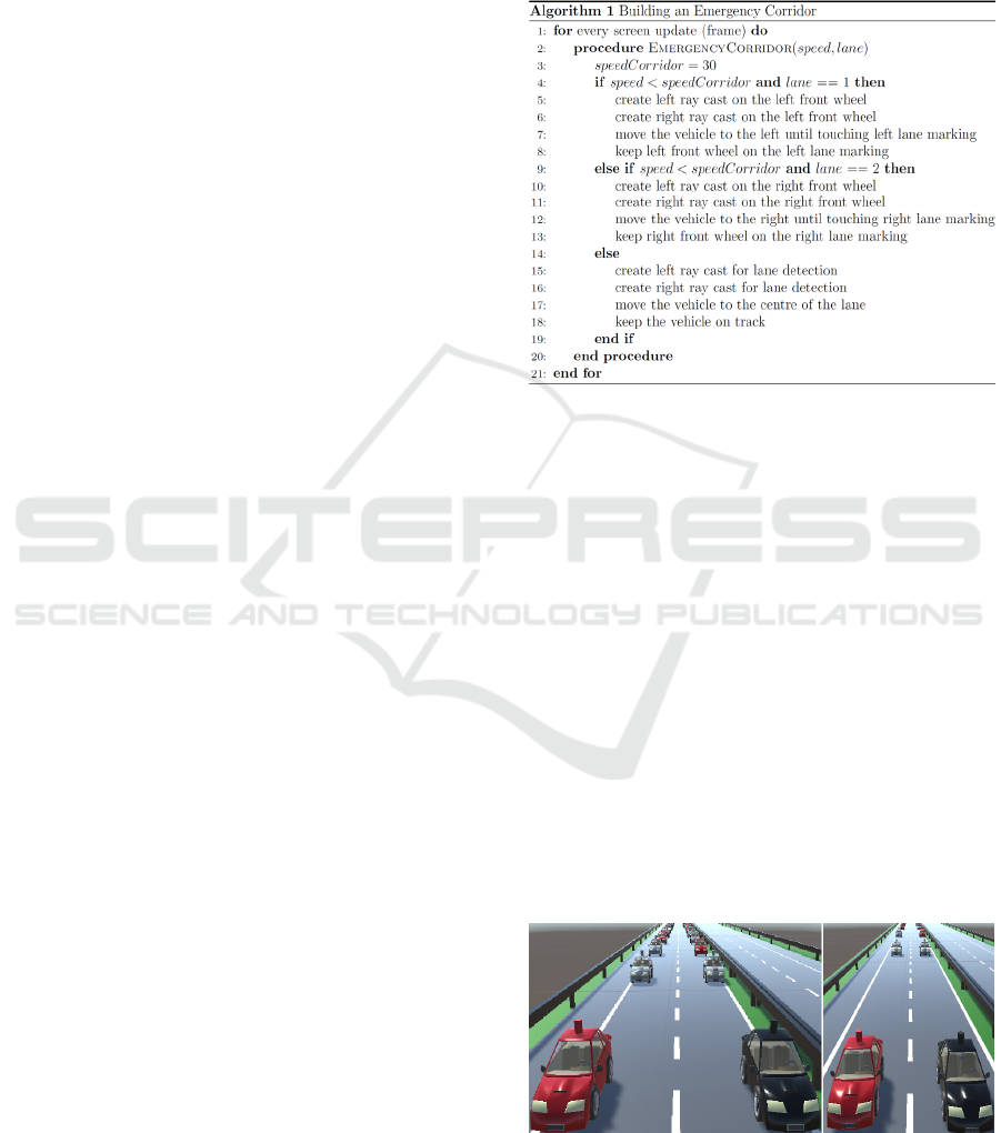
The algorithm (Fig. 4) for the formation of the
rescue corridor works in accordance with a simple
principle. The numbering of the lanes starts at the
middle crash barrier.
Figure 4: Algorithm of building an emergency corridor.
4.1 Building an Emergency Corridor:
Slow-moving Traffic
The emergency corridor is always formed as soon as
the speed falls below a certain value (30 km/h). In the
case of slow-moving traffic, the vehicles
automatically form a rescue corridor. This can be seen
in figure 5, left. Figure 5 also shows that all vehicles
drive in one row in order. This is done by keeping the
safety distance to the front vehicle and drive at equal
speed. Therefore, the road is used completely as well.
This also ensures that the vehicles stop in time to
avoid injuring the passengers. As soon as the distance
to the following vehicle increases, the vehicles
accelerate automatically. When the speed increases,
the vehicles automatically increase the safety distance
and close the gap for the emergency vehicles (Fig. 5,
right).
Figure 5: Building an emergency corridor at slow-moving
traffic on a two-lane motorway. Left: Open an emergency
corridor. Right: Close an emergency corridor.
Unity 3D Simulator of Autonomous Motorway Traffic Applied to Emergency Corridor Building
201
4.2 Building an Emergency Corridor:
Obstacles in Front
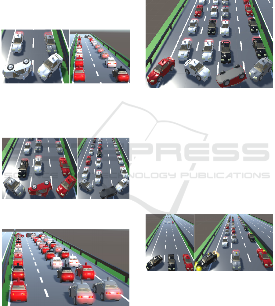
This experiment shows the formation of the rescue
corridor when approaching any obstacles. For
example, this could be an accident that blocks the
total road. The next figure 6 shows the formed rescue
corridor in the event of an accident on a two-lane
motorway.
Figure 6: Building an emergency corridor in the event of an
accident on a two-lane motorway. Left: Front-view. Right:
Rear-view.
The automatic building of an emergency corridor in
the case of an accident was also tested on a three-lane
motorway. This can be seen in the next figure 7.
Figure 7: Building an emergency corridor in the event of an
accident on a three-lane motorway. Left: Front-view with
normal lanes. Right: Front-view with extra wide lanes.
Figure 8: Building an emergency corridor on a three-lane
motorway with normal lanes (Rear-view).
The vehicles know the width of the lane. Thus, this
width can be incorporated into the formation of the
rescue corridor. Therefore, the width of the lane can
vary. This can be seen in figure 7, right and figure 8.
To ensure that the simulation also works for more
than three lanes of a motorway, a four-lane motorway
(Fig. 9) was also built and tested successfully.
Figure 9: Building an emergency corridor in the event of an
accident on a four-lane motorway.
4.3 Building an Emergency Corridor:
Front Tire Bursting
To investigate whether the rescue corridor can be
formed at any unexpected time, an unexpected
accident was simulated while driving. This showed
that the autonomous vehicles at any opportunity could
build an emergency corridor. The simulation was
random to cover every possible case. Therefore, the
vehicle for the accident, the rotation in degrees and
the time of the accident were determined by chance.
This simulation is intended to simulate the bursting of
a front tire while driving. The following figure 10
illustrates this example.
Figure 10: Simulation of a front tire bursting while driving.
Left: Not built emergency corridor. Right: Built emergency
corridor.
The vehicles in front of the accident vehicle continue
driving and contact the rescue service. The other
vehicles stop to avoid a collision. Figure 10, right also
shows that the car’s lidar has coloured yellow. This
illustrates the arrival of a message. Due to these
experiments, the unexpected and unimaginable
IoTBDS 2020 - 5th International Conference on Internet of Things, Big Data and Security
202

behaviour through the physics of the vehicle can be
shown. Above all, the reaction to the adjustment of
the rotation was always different. This results from
the G-forces, which are dependent on the direction
and rotation of the vehicle. Further experiments and
considerations of this work can be found in section 6.
5 CONCLUSIONS
The presented simulator helps to demonstrate the
behaviour of autonomous vehicles in the event of
unforeseeable accidents in motorway traffic. The
vehicles for the simulation were imported from the
Unity Asset Store and extended in our project. The
lane and distance detection was performed with ray
casts. The rotation detection of the self-driving car is
done by monitoring the own car spin on the road. The
collision detection could be realised by the methods
provided by Unity. The vehicles move autonomously.
These automatically accelerate, keep the safety
distance, adjust the safety distance to their speed and
adjust the emergency corridor to the width of the lane.
If the speed falls below a certain value, an emergency
corridor will be opened automatically. This is
important in slow-moving traffic. If the speed
exceeds a certain value, the rescue corridor will be
closed automatically. Communication between
vehicles is very important in simulation and practice.
The vehicles have to exchange messages about the
situation on the road. This allows to make decisions
and to forward the direction or the position of the
accident vehicle. The exchange of messages is
realised via an ellipse, which contains the vehicles in
the surrounding area as a game object. Some
experiments were carried out to test the functionality.
These test cases were randomly generated to cover as
many different behaviours as possible. The
communication between autonomous vehicles in
practical applications was also briefly explained.
Below, lane, distance, rotation and urban
environment detection in practice have been
discussed. Furthermore, the sensors used in
autonomous vehicles were explained. The levels of
automation were also presented to be able to integrate
the formation of the rescue corridor into the driving
process. From the third level onwards, the vehicle
moves autonomously on the road. From this level on,
an emergency corridor can be automatically built by
the respective vehicle. In this work the simulation is
based on these parameters: the total number of lanes
on the motorway, the own lane number and the width
of the lane.
6 FUTURE WORK
The following questions also arise: What happens if
the autonomous vehicle breaks through the crash
barrier and enters oncoming traffic in the event of an
unforeseeable accident in the opposite lane? What
happens in the case of an unexpected deer crossing?
To answer these questions further implementations
and experiments are necessary. In this simulator the
lane detection is done using ray casts. Therefore, the
next step is the implementation of a lane detection
using video cameras (image recognition) as known
from practice. It is possible that not only sequential
programming but also the methods of machine
learning will be investigated. It would also be
interesting to see how the autonomous vehicles
behave when, for example, zipper procedures are
used on a construction site or driving onto a
motorway in flowing traffic. In the current
simulation, the vehicles drive at equal speed in each
lane and keep the safety distance to the following
vehicle. This is why the autonomous vehicles drive
side by side in each lane. This optimum uses the space
on the road, but this does not quite correspond to
reality. What will also be transferred to the simulator
and would be conceivable in practice is that each lane
has its specific speed. For example, on a three-lane
motorway, the autonomous vehicles drive up to 100
km/h in the right lane. Vehicles with speed between
101 and 119 km/h drive in the middle lane. From 120
km/h on, the vehicles drive in the left lane. The driver
of the autonomous vehicle can set this maximum
speed himself. Further experiments on this topic will
follow.
REFERENCES
Alheeti, K. M. A., Gruebler, A., McDonald-Maier, K. D.,
2016. An Intrusion Detection System against Black
Hole Attacks on the Communication Network of Self-
Driving Cars, Sixth International Conference on
Emerging Security Technologies (EST), pp. 86-91,
ISBN 978-1-4673-9799-5.
Azmat, M., Schuhmayer, C., 2015. Self Driving Cars.
Academia.edu. [online]. Available at:
https://www.academia.edu/14750561/Self_Driving_C
ars_Future_has_already_begun.
Behrisch, M., Bieker, L., Erdmann, J., Krajzewicz, D.,
2011. Sumo - Simulation of Urban MObility: an
overview, The Third International Conference on
Advances in System Simulation, pp. 63-68, ISBN 978-
1-61208-169-4.
Buchenscheit, A., Schaub, F., Kargl, F., Weber, M., 2018.
A VANET-based emergency vehicle warning system,
Unity 3D Simulator of Autonomous Motorway Traffic Applied to Emergency Corridor Building
203

2009 IEEE Vehicular Networking Conference (VNC),
pp. 1-8, ISBN 978-1-4244-5685-7.
Dallmeyer, J., Timm, I. J., 2012. MAINSIM – MultimadAl
INnercity SIMulation, Conference on Artificial
Intelligence (KI2012), pp. 125-129.
De Oliveira, J., 2018. Jump start your autonomous
simulation development with Unity’s SimViz Solution
Template, Blogs.unity3d.com. [online]. Available at:
https://blogs.unity3d.com/2018/11/08/jump-start-your-
autonomous-simulation-development-with-unitys-
simviz-solution-template/?_ga=2.67797393.
1847280321.1575365091-841449263.1575365091.
De Oliveira, J., Duong, R., 2018. AirSim on Unity:
Experiment with autonomous vehicle simulation,
Blogs.unity3d.com. [online]. Available at:
https://blogs.unity3d.com/2018/11/14/airsim-on-unity-
experiment-with-autonomous-vehicle-simulation/
Dębiński, M., Jukowski, M., Bohatkiewicz, J., 2018.
Emergency Corridors - Necessary Solutions in a
Modern Road Network, MATEC Web of Conferences
231 (GAMBIT 2018), pp. 1-6.
Hartenstein, H., Laberteaux, L. P., 2008. A tutorial survey
on vehicular ad hoc networks, IEEE Communications
Magazine (Volume: 46, Issue: 6), pp. 164-171, ISSN
0163-6804.
Jain, R., 2014. Introduction to Vehicular Wireless
Networks, cse.wustl.edu. [online]. Available at: https://
www.cse.wustl.edu/~jain/cse574-14/ftp/j_08vwn .pdf.
Leftlaneadvisors, 2013. NHTSA Levels of Vehicle
Autonomy Infographic, Leftlaneadvisors.com. [online].
Available at: https://leftlaneadvisors.com/project/
nhtsa-levels-of-vehicle-autonomy-infographic/.
MATSim, 2019. Agent-Based Transport Simulations,
Matsim.org. [online]. Available at: https://www.matsim.
org/about-matsim.
PTVGroup, 2019. Traffic Flow Simulation with PTV
Vissim, Ptvgroup.com. [online]. Available at:
https://www.ptvgroup.com/en/solutions/products/ptv-
vissim/areas-of-application/traffic-flow-simulation/.
Unity Asset Store, 2019. Car'Toon : The Sport Car with
interior, Assetstore.unity.com. [online]. Available at:
https://assetstore.unity.com/packages/3d/vehicles/land/
car-toon-the-sport-car-with-interior-62697.
Urooj, S., Feroz, I., Ahmad, N., 2018. Systematic literature
review on user interfaces of autonomous cars: Liabilities
and responsibilities, 2018 International Conference on
Advancements in Computational Sciences (ICACS), pp.
1-10, ISBN 978-1-5386-2172-1.
IoTBDS 2020 - 5th International Conference on Internet of Things, Big Data and Security
204
