
Usage of UML Combined Fragments in Automatic Function Point
Analysis
Ilona Bluemke
a
and Agnieszka Malanowska
b
Institute of Computer Science, Warsaw University of Technology, Nowowiejska 15/19, Warsaw, Poland
Keywords: Combined Fragments, UML, Sequence Diagrams, Function Point Analysis, FPA, IoTEAM, Testing Effort
Estimation.
Abstract: Combined fragments, introduced in UML 2.0 and allowing to express complex communication scenarios in
sequence diagrams, are rarely the subject of research. In this paper, we present a method to transform nine of
UML 2.x combined fragments, i.e. alt, opt, break, neg, ignore, consider, assert, strict and critical, into the set
of interaction variants. Our proposition takes advantage of the simple fact that each sequence diagram
containing any number of combined fragments can be replaced with some number of simpler diagrams
representing single scenarios and not containing any combined fragments. This transformation can be fully
automated. Our method was developed as a pre-processing stage in the automatic FPA analysis, which is used
in test effort estimation approach, but can be used independently as well.
1 INTRODUCTION
The Unified Modeling Language (UML) is widely
used to present the design of a software system by
various types of diagrams. We have taken the
advantage of the UML popularity in our approach to
the semi-automatic test effort estimation approach
performed on the basis of class and sequence
diagrams (Bluemke et al., 2020). It is a combination
of automatic Function Point Analysis (FPA)
performed automatically using data from class and
sequence diagrams (Uemura et al., 1999; Uemura, et
al., 2001) and the Test Point Analysis (TPA)
(Veenendaal et al., 1999), which requires function
points. It has been implemented in the IoTEAM
(Implementation of Testing Effort Assessment
Method) tool (Bluemke et al., 2020).
As both methods used in this approach were
proposed 20 years ago, they need an adaptation to the
current versions of the standards. That is why we have
extended the original methods, so that they can treat
the project developed according to any version of
standards as a proper input (Malanowska, 2019). In
(Malanowska et al., 2020) we have proposed a simple
incorporation of ISO 25010 quality standard into the
TPA. Here we present our idea on how to add the
a
https://orcid.org/0000-0002-2894-5976
b
https://orcid.org/0000-0001-8876-9647
information contained in the UML combined
fragments to the automatic FPA. Both improvements
were implemented in the new version of our testing
effort estimation tool, IoTEAM 2.0 (Bluemke et al.,
2020; Malanowska et al., 2020). It is worth noting
that, although our proposition was prepared in the
context of testing effort estimation method, it can be
perceived independently. The approach described
below affects only the method of automatic FPA and
its results. Moreover, our proposition works as a pre-
processing stage before the actual automatic FPA and
is defined on the basis of the UML definitions of
particular combined fragments. It means that,
although we have designed it to be compliant with the
automatic FPA, the same or slightly modified
approach could be used for other purposes.
The paper is organized as follows. In Section 2 we
briefly describe the automatic FPA and the UML
combined fragments. In Section 3 we explain the idea
and definitions for our transformation from sequence
diagrams (called interactions in the UML) to the so-
called interaction variants. Section 4 describes the
rules of the mapping. In Section 5 there is an example
illustrating the usage of this approach in our tool.
Section 6 contains brief review of the related
literature and finally, Section 7 concludes the paper.
Bluemke, I. and Malanowska, A.
Usage of UML Combined Fragments in Automatic Function Point Analysis.
DOI: 10.5220/0009348303050312
In Proceedings of the 15th International Conference on Evaluation of Novel Approaches to Software Engineering (ENASE 2020), pages 305-312
ISBN: 978-989-758-421-3
Copyright
c
2020 by SCITEPRESS – Science and Technology Publications, Lda. All rights reserved
305

2 THEORETICAL
BACKGROUND
The approach to the usage of meaning of combined
fragments, introduced in Section 3, was defined in the
context of testing effort estimation method and as a
pre-processing stage before the automatic FPA. The
latter is briefly described in Section 2.1. Section 2.2
quickly recalls the concept of combined fragments.
2.1 Automatic Function Point Analysis
The automatic approach to the FPA considered in our
work was proposed in 1999 by Uemura et al.,
(Uemura et al., 1999; Uemura et al., 2001). It uses the
UML class and sequence diagrams to perform first
five steps of the IFPUG FPA method. Its main aim is
to determine Data Functions and Transactional
Functions and there the sequence diagrams are the
primary source of information. The authors of this
method have defined five patterns of message
sequence to determine types and complexities of
Transactional Functions. As the approach of Uemura
et al. was defined for UML 1.0 and did not cover
mandatory reply messages, we have added two
similar patterns for the cases when reply messages are
used (Bluemke et al., 2020; Malanowska, 2017).
However, until now, the new elements of UML 2.x –
such as the combined fragments – were still
unsupported.
2.2 UML Combined Fragments
Combined fragments, a concept introduced in UML
2.0, are elements of the sequence diagrams. They
assign special meaning to the part of the interaction
and allow to present complex interaction scenarios on
a diagram. As the UML specification indicates, the
meaning of a particular combined fragment is defined
by its interaction operator (OMG, 2017), which can
be understood as its type. There are 12 interaction
operators. A combined fragment is built of at least
one region, called an interaction operand. Each
interaction operand can have a guard, which is a
condition that must be satisfied if the content of the
operand is to be executed in the interaction.
3 TRANSFORMATION BASICS
The original method of automatic FPA on the basis of
the class and sequence diagrams, proposed by
Uemura et al., (Uemura et al., 1999; Uemura et al.,
2001), takes as an input sequence diagrams without
the combined fragments. If we were able to reduce
complex diagrams with combined fragments to the
simpler ones without fragments, it would be possible
to apply automatic FPA in its basic form to those
simple sequence diagrams. Such transformation can
be defined and in Section 4 we propose the rules of it.
The mapping described there is then used as a pre-
processing stage before the automatic FPA. In this
section, we explain the basic idea of the
transformation and define the necessary terms.
3.1 The Idea of the Transformation
Each combined fragment represents one or more
scenarios of communication. Each sequence diagram
containing any number of combined fragments can be
replaced with some number of simpler diagrams
representing single scenarios and not containing any
combined fragments. The set of simple diagrams
(each of which represents one scenario of
communication) is semantically equivalent to the
original diagram with combined fragments, provided
that the semantics of all fragments is preserved. All
these simple diagrams can be used as input for the
original method of the automatic FPA.
The most important part of the proposed
transformation is the method of replacing the content
of a single combined fragment with the set of
equivalent parts of communication. If we had the
method to transform a sequence diagram with one
combined fragment to the set of corresponding
diagrams without fragments, it would be easy to
extend it, so that any number of combined fragments
in any configuration, could be transformed. To
support complex configurations of the combined
fragments, the proposed approach for a single
fragment has to be used iteratively – to cover all
fragments on the same nesting level – and
recursively – to take into account all levels of
nesting. The input diagram will be transformed to the
subsequent intermediate diagrams with the smaller
number of fragments and at the end, all combined
fragments will be reduced. The process of combined
fragments reduction must be performed in a top-
down manner, i.e. the combined fragments on the
same nesting level should be simplified from the top
to the bottom of the diagram and the nested
fragments have to be reduced from the enclosing
fragment to the enclosed fragment.
To sum up, our transformation method is based
on the recursive and iterative application of the
rules presented in Section 4.
ENASE 2020 - 15th International Conference on Evaluation of Novel Approaches to Software Engineering
306

3.2 Interaction, Message and Lifeline
Variants
We have defined three terms to describe the
transformation more formally, i.e.: interaction
variant, lifeline variant and message variant. Each
term contains all elements of the corresponding
original term used in the automatic FPA. Hence, the
usage of variants implies an easy way of modification
of the original method and its implementation
presented in (Bluemke et al., 2020; Malanowska,
2017). The interactions, messages and lifelines just
need to be replaced with their variants and the rest of
the automatic FPA does not need any modification.
An interaction variant is an intermediate or final
result of the transformation. It can represent one or
more scenarios – depending on whether it is a form of
the final reduced diagram or not – but not the whole
original complex scenario. The interaction variant
consists of lifeline variants and message variants, as
it is necessary to differentiate between the same
messages or lifelines appearing in the different
interaction variants. Not all messages and lifelines
from the original interaction have to appear in its
particular variants. Lifeline variants corresponding to
all lifelines from the original interaction are included
in the given interaction variant.
A message variant is an intermediate layer
between the message from the original sequence
diagram and the particular interaction variant: it
connects them. It may occur that the reply to a
synchronous call (or vice versa) is not present in the
particular interaction variant after the reduction, so it
is necessary to store information about the opposite
message variant (i.e. the message variant
corresponding to the message which is opposite to the
considered one) inside the given message variant. The
message variant should also store information about
the source and target lifeline variants, i.e. the lifeline
variants related to the source and target lifelines of the
given message.
Similarly, a lifeline variant connects the lifeline
from the original interaction to the particular
interaction variant. In the original automatic FPA,
messages touching the given lifeline or outgoing from
the given lifeline are important. In the lifeline variant,
they are replaced with the corresponding message
variants. If a particular message touches the given
lifeline or goes out of it and occurs in the given
interaction variant, its message variant will be
included in a proper collection of messages within the
given lifeline variants.
4 TRANSFORMATION RULES
As we stated before, the rules for replacing a single
combined fragment with a set of the corresponding
parts of interactions are crucial in this approach. We
divide all combined fragments into 3 categories,
namely: easy to be reduced, not requiring
reduction and unsupported in this approach. The
rules of reduction for all supported combined
fragments from the first two categories are described
below, however 3 out of 12 fragments belong to the
last group. Rules for all supported types of interaction
operators are based on their meaning defined in the
UML specification (OMG, 2017).
At the moment, our approach does not cover par,
seq and loop combined fragments, as in their case, it
is difficult or inefficient to define strict rules of the
transformation. The frames of those types of
fragments are simply ignored, but their content is
preserved. As a result, we process them in exactly the
same manner as the fragments not requiring any
reduction – although because of different reasons: the
rule for the unsupported types of combined fragments
is the same as described in Section 4.2.
4.1 Combined Fragments Easy To Be
Reduced
The first group consists of 4 combined fragments (alt,
opt, break and neg), which can be easily decomposed
to the simple scenarios according to their definitions.
The input interaction is mapped to the set of a few
interaction variants representing all possible
scenarios. Usually, the resulting interaction variants
differ from the original diagram.
As the UML specifies, at most one operand of the
alt combined fragment will be executed – in case its
guard is satisfied. It means that the number of
possible scenarios is (approximately) equal to the
number of alt operands. Each scenario contains all
elements of the interaction placed before and after the
alt fragment and the content of one of its operands.
Each of those scenarios illustrates the communication
in case when the given guard is satisfied. It may
happen that none of the operand conditions is
satisfied and if there is no operand with an else guard,
no operand should be executed at all. It means that if
none of the operands has an else guard, there should
exist one more possible interaction variant, which
contains everything from the original interaction
except of the alt fragment and its content.
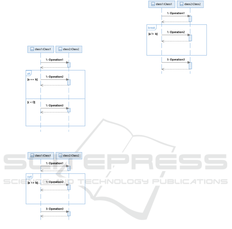
The example of interaction with alt combined
fragment which does not contain operand with else
guard is presented in Figure 1. According to the above
Usage of UML Combined Fragments in Automatic Function Point Analysis
307
rules, it will be transformed to three interaction
variants presented in Figure 5 – Figure 7. Supposing
that the condition of the second operand of the alt
fragment from Figure 1 (i.e. c < 0) is replaced with
the else guard, there are only two possible interaction
variants, identical to those presented in Figure 6 and
Figure 7.
Figure 1: Interaction with alt combined fragment without
else guard.
Figure 2: Interaction with opt combined fragment.
The definition of the opt combined fragment
indicates that its content can be executed – if the
guard condition is satisfied – or not. There are two
possible scenarios and two interaction variants to
consider. There should be one interaction variant with
all messages from the original interaction and without
the frame of opt fragment (but with preserved content
of that frame). The other interaction variant should
contain everything from the original interaction
except of the opt frame and its content. The former
scenario corresponds to the situation when the guard
is satisfied and the latter – to the opposite one. A
sequence diagram with an opt fragment is presented
in Figure 2. It can be divided into two interaction
variants shown in Figure 7 and Figure 8.
Figure 3: Interaction with break combined fragment.
Similarly, the break combined fragment can also
be reduced to two interaction variants. In a typical
case, the guard of a break fragment is not satisfied and
the corresponding interaction variant should contain
everything from the original interaction except of that
fragment and its content. UML specification
indicates, that in the non-typical situation, when the
guard is true, the content of the combined fragment is
executed ‘instead of the remainder of the enclosing
interaction fragment’ (OMG, 2017). It means that, if
an exception occurs, the interaction variant should be
built of all messages placed before the break fragment
and the content of that fragment. All messages placed
after the fragment inside the same interaction
fragment (i.e. in an interaction fragment enclosing the
break combined fragment) have to be rejected. The
contents of upper-level interaction fragments must be
preserved. In this case, there are two possible
interaction fragments enclosing the break fragment:
the whole interaction or the operand of the enclosing
combined fragment in which it is placed, depending
on the nesting of the given fragment.
Here we assume that a message is placed after the
break fragment if a preceding message touching a
source or target lifeline of a given message is
enclosed by the fragment, but the given message is
not included in the fragment. All messages dependent
on those placed after the break fragment are also
treated as placed after that fragment. It implies that if
the source and target lifelines of a particular message
are not covered by the break fragment, this message
will not be treated as placed after the fragment and
will not be ignored in an interaction variant of a
breaking scenario. The example of interaction with
correctly placed break combined fragment can be
seen in Figure 3. It can be mapped to two interaction
variants shown in Figure 7 (in a typical case, when
the guard is not satisfied) and Figure 6 (in breaking
scenario, when the guard is satisfied).
ENASE 2020 - 15th International Conference on Evaluation of Novel Approaches to Software Engineering
308
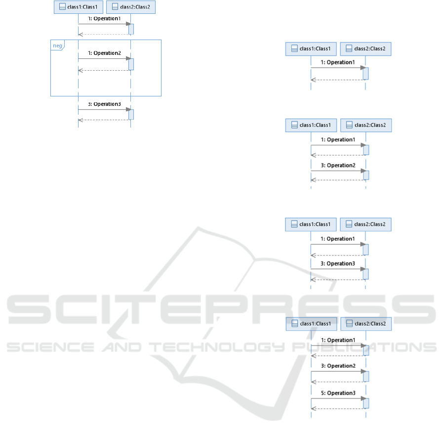
Figure 4: Interaction with neg combined fragment.
The content of the neg fragment should never
occur in a real communication. It means that there is
only one possible interaction variant of
communication with neg fragment: its frame and
content must be ignored and the rest of the whole
interaction will be executed. The exemplary
interaction with neg fragment is illustrated in Figure
4. The only possible interaction variant which can be
derived from that sequence diagram can be seen in
Figure 7.
4.2 Combined Fragments Not
Requiring Reduction
It turns out that there are 5 types of combined
fragments which decomposition can be reduced to
ignoring the fragment frame while preserving its
content. Ignore, consider, assert, strict and critical
combined fragments belong to this group.
Ignore combined fragment indicates the
existence of messages not included inside it, but there
is no more information about those messages. On the
other hand, consider fragment indicates that the
messages inside it are important, but in a real
communication some other messages can also occur
and again we do not know anything about them. As
those fragments in fact do not provide any additional
information to the existing order of messages, we
could only preserve it and ignore the existence of
frames enclosing those combined fragments.
Further, the assert combined fragment is a
representation of the ‘only valid continuation’ (OMG,
2017). If there is only one possible continuation of
communication, it can be mapped to exactly one
interaction variant containing everything before the
fragment and this one possible continuation. This
reasoning can be reduced to preserving all messages
from the original interaction and ignoring the
existence of the frame. Similarly, the strict combined
fragment indicates the order of messages that is
already visible on the diagram. Its reduction should
consist of preserving the existing order of messages
from the fragment and the rest of the diagram.
Figure 5: Interaction variant containing only operation 1.
Figure 6: Interaction variant containing operations 1 and 2.
Figure 7: Interaction variant containing operations 1 and 3.
Figure 8: Interaction variant containing all operations 1-3.
A critical combined fragment is worth a bit more
attention. The information given by the critical
interaction operator that the content of the fragment
must be executed atomically is in fact important only
in combination with the possibility of parallel
execution, i.e. when the critical fragment is nested in
par or seq combined fragments. In other cases, the
messages are always executed sequentially and there
is no possibility to interrupt the execution of all those
messages as a whole. It means that the information
provided by this combined fragment is essential only
to define proper interaction variants of the enclosing
par or seq combined fragments, but not to define
rules of reduction of the given critical fragment and
its content. As we decompose the combined
Usage of UML Combined Fragments in Automatic Function Point Analysis
309
fragments in a top-down manner, when the critical
fragment appears, the enclosing fragments have
already been decomposed and, at this point, the
critical region has no impact on the method of
defining interaction variants for its content. This
region just does not provide any new information.
In each case described above, the graphical
example of the transformation would be similar to
this presented in Figure 2 (supposing the type of the
combined fragment belongs to the second category,
eg. assert) and Figure 8 – after the transformation
there is only one interaction variant and the only
difference between the figures is the lack of the
frame.
5 EXAMPLE
To present the idea of the mapping described in
previous sections, we have modified an exemplary
system for a guesthouse presented in (Bluemke et al.,
2020; Malanowska, 2017).
The exemplary system is intended to support a
small guesthouse and provides several functions for
the guests and the receptionists, e.g. room booking,
payment service, booking prolongation etc. There are
two types of accomodation: three-person and four-
person rooms. In the first version of this system, the
process of booking was presented on a different
sequence diagrams for each type of the room. The
only difference between those diagrams was the
usage of lifeline representing three- or four-person
room. It was an obvious place to use an alt combined
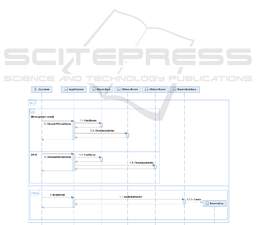
fragment. Moreover, the room booking consists of
two main stages: selection of a room with checking
its availability and creation of a reservation for the
selected room. The order of those activities is strict.
Further, the booking is an atomic process which
cannot be disturbed. It all leads to the sequence
diagram presented in Figure 9. The semantics of the
guesthouse system presented in (Bluemke et al.,
2020) is preserved, the only difference is that the two
sequence diagrams of room reservation were replaced
with the one containing nested combined fragments
(Malanowska, 2019), as they are now supported in
our implementation of the automatic FPA in the
IoTEAM 2.0 tool (Malanowska et al., 2020;
Malanowska, 2019).
Although now there is only one sequence diagram
for room booking, our IoTEAM 2.0 tool properly
distinguished two interaction variants of this
interaction, what is shown in Figure 10. According to
the rules defined earlier, the strict and critical
combined fragments do not increase the number of
interaction variants, only the alt fragment causes that
there appear two resulting interaction variants. Each
of those two interaction variants represents the whole
scenario of communication for a different case:
booking of three- or four-person room. Both
interaction variants are then used to determine the
Transactional Functions in the automatic FPA.
Figure 9: The sequence diagram for room booking with nested combined fragments (based on (Malanowska, 2019)).
ENASE 2020 - 15th International Conference on Evaluation of Novel Approaches to Software Engineering
310
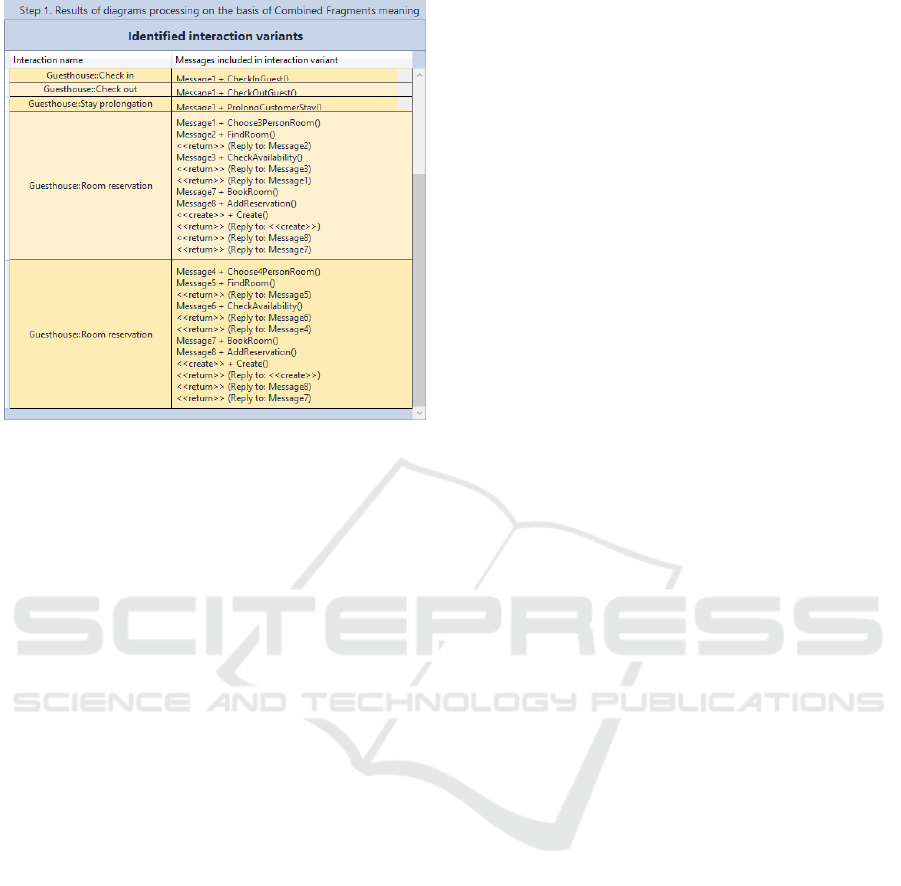
Figure 10: Interaction variants identified for the exemplary
guesthouse system (based on (Malanowska, 2019)).
6 RELATED WORK
Sequence diagrams are usually used to specify how a
use case or a method should be implemented. Based
on the sequence diagram, the programmers can write
code that implements methods, so they can also be
used a basis for test preparation.
Nguyen et al., (Nguyen et al., 2010) introduced a
tool able to verify if a Java program correctly
implements its sequence diagram specification. This
tool, as the authors claim, can effectively find bugs in
the software and is easy to use. Some few annotations
in the source code have to be introduced.
Sometimes sequence diagrams are used in context
of the test generation process. Vu et al. (Vu et al.,
2015) proposed a method to automatically generate
test data on the basis of sequence diagrams, class
diagrams, and Object Constraint Language (OCL). In
this method it is possible to generate all test scenarios
in special case by exploring the message sequence
with their possible interleaving in par or seq
fragments. Test data for testing loop fragment is also
generated. Lund et al. (Lund et al., 2006) prepared the
algorithm to obtain software tests from the sequence
diagram. The input diagrams have to use previously
defined operational semantics and are allowed to
contain neg and assert combined fragments.
Interestingly, in this approach, the resulting tests have
also the form of the sequence diagrams, but with the
only one lifeline representing the test. Seo et al. (Seo
et al., 2016) observed that with combined fragments
an automatic generation of test cases from sequence
diagram is very complicated. To solve this problem,
they propose a model transformation from sequence
diagrams into activity diagrams.
Several researchers, e.g. Ameedeen et al.,
(Ameedeen et al., 2008), convert UML 2.x sequence
diagrams into Petri Nets. Alhroob et al., (Alhroob et
al., 2010) transform the UML sequence and class
diagrams into High Level Petri Nets. Based on Petri
Nets some non-functional properties can be deduced.
Since the UML specification allows for varying
interpretations of some language constructs, Micskei
et al., (Micskei et al., 2011) compared 13 semantics
of the sequence diagrams suited for different
purposes. They have focused on the elements
introduced in UML 2.0, particularly on combined
fragments and their usage. Similarly, as loop, break
and strict operators can introduce ambiguity in the
interpretation and understanding of sequence
diagrams, Ejnioui et al., proposed in (Ejnioui et al.,
2013) a formal model in operational semantics based
on Abstract State Machines (ASM). This formal
model defines the semantics of the operators. Such
formal models may be very useful while modeling
embedded software, especially in distributed or
parallel environments. Dhaou et al., also worked on
the semantics of the sequence diagram in context of
the distributed systems. In (Dhaou et al., 2017), they
defined causal semantics for the opt, alt, loop and seq
fragments and dealt with the nested combined
fragments. Later, in (Dhaou et al., 2018), they also
included par fragment in their approach and derived
the operational semantics for the sequence diagrams
with nested combined fragments.
As can be seen, there are not many publications
regarding the combined fragments. Moreover, the
existing ones can be grouped into only a few topics,
such as formal methods or test generation. None of
the approaches found in the literature deals with the
combined fragments in the context of the automatic
FPA or testing effort estimation method.
7 CONCLUSIONS
The method of automatic FPA we have used in our
previous works performs the analysis on the basis of
the UML class and sequence diagrams.
Unfortunately, it is not suited for the UML 2.x
features, such as combined fragments, as it was
proposed earlier. In this paper, we have described our
proposition of combined fragments usage in the
automatic FPA, which works as a pre-processing
stage before the main analysis. It covers 9 out of 12
Usage of UML Combined Fragments in Automatic Function Point Analysis
311

UML combined fragments. We have also proposed
three new terms, i.e. interaction variants, message
variants and lifeline variants. Our method transforms
original interactions into the interaction variants,
which contains message and lifeline variants.
Despite the fact that the approach presented above
was prepared in the context of testing effort
estimation process, it can be used almost
independently of any other methods. Although it is
very simple and based on the UML definitions, it
seems that it has not been proposed before. In fact, we
have observed very small interest in the concept of
combined fragments in the literature. As the loop, par
and seq combined fragments are not covered in our
proposition, there is a need to figure out an acceptable
and reasonable idea to include them in this method.
In the future we also plan to add UML interaction uses
support to the automatic FPA.
REFERENCES
Alhroob, A., Dahal, K., Hossain, A., 2010. Transforming
UML Sequence Diagram to High Level Petri Net. In
2nd Int. Conf. on Software Technology (ICSTE). IEEE.
V1-260-V1-264. DOI: 10.1109/ICSTE.2010.5608842.
Ameedeen, M.A., Bordbar, B., 2008. A model driven
approach to represent sequence diagrams as free choice
Petri nets. In 2008 12th Int. IEEE Enterprise
Distributed Object Computing Conf. IEEE. 213-221.
DOI: 10.1109/EDOC.2008.42.
Bluemke, I., Malanowska, A., 2020. Tool for Assessment
of Testing Effort. In Proc. of the 14th Int. Conf. on
Dependability of Computer Systems DepCoS-
RELCOMEX. Springer. 69-79. DOI 10.1007/978-3-
030-19501-4_7.
Dhaou, F. et al., 2017. A Causal Semantics for UML2.0
Sequence Diagrams with Nested Combined Fragments.
In Proc.of the 12th Int. Conf. on Evaluation of Novel
Approaches to Software Engineering. SCITEPRESS.
47-56. DOI: 10.5220/0006314100470056.
Dhaou, F. et al., 2018. An Operational Semantics of
UML2.X Sequence Diagrams for Distributed Systems.
In Evaluation of Novel Approaches to Software
Engineering. 12th Int. Conf., ENASE 2017. Springer.
158-182. DOI: 10.1007/978-3-319-94135-6_8.
Ejnioui, A. et al., 2013. Formal Semantics of Interactions in
Sequence Diagrams for Embedded Software. 2013
IEEE Conf. on Open Systems (ICOS). IEEE. 106-111.
DOI: 10.1109/ICOS.2013.6735057.
Lund, M.S., Stølen, K., 2006. Deriving tests from UML 2.0
sequence diagrams with neg and assert. In Proc. of the
2006 int. workshop on Automation of software test.
ACM. 22-28. DOI: 10.1145/1138929.1138934.
Malanowska, A., 2017. Testing effort assessment [BSc
thesis]. Warsaw University of Technology, Institute of
Computer Science (in Polish).
Malanowska, A., 2019. Improving testing effort estimation
method with UML combined fragments and ISO/IEC
25010:2011 software quality model support [MSc
thesis]. Warsaw University of Technology, Institute of
Computer Science (in Polish).
Malanowska, A., Bluemke I., 2020. ISO 25010 Support in
Test Point Analysis for Testing Effort Estimation. In
Jarzabek S. et al., Integrating Research and Practice in
Software Engineering. Springer. 209-222. DOI:
10.1007/978-3-030-26574-8_15.
Micskei, Z., Waeselynck, H., 2011. The many meanings of
UML 2 Sequence Diagrams: a survey. Soft Sys Model,
Springer, 10(4):489-514, DOI 10.1007/s10270-010-
0157-9.
Nguyen, D.P. et al., 2010. Verifying implementation of
UML sequence diagrams using Java PathFinder. In
2010 2nd Int. Conf. on Knowledge and Systems
Engineering. IEEE. 194-200. DOI:
10.1109/KSE.2010.29.
OMG, 2017. OMG Unified Modeling Language (OMG
UML): Version 2.5.1.
Uemura, T. et al., 1999. Function Point Measurement Tool
for UML Design Specification. In Proc.: 6th Int.
Software Metrics Symposium. IEEE. 62-69. DOI:
10.1109/METRIC.1999.809727.
Uemura, T. et al., 2001. Function-point analysis using
design specifications based on the Unified Modelling
Language, J Software Mainten Evol Res Pract
, John
Wiley & Sons, 13(4):223-243, DOI: 10.1002/smr.231.
van Veenendaal, E.P.W.M., Dekkers, T., 1999.
Testpointanalysis: a method for test estimation. In
Kusters R. et al., Project Control for Software Quality.
Vu, T.D. et al., 2015. A Method for Automated Test Data
Generation from Sequence Diagrams and Object
Constraint Language. In SoICT 2015. ACM. 335–341.
DOI: 10.1145/2833258.2833294.
Seo, Y. et al., 2016. Techniques to Generate UTP-based
Test Cases from Sequence Diagrams Using M2M
(Model-to-Model) Transformation. In 2016 IEEE/ACIS
15th Int. Conf. on Computer and Information Science
(ICIS). IEEE. 1-6. DOI: 10.1109/ICIS.2016.7550832.
ENASE 2020 - 15th International Conference on Evaluation of Novel Approaches to Software Engineering
312
