
Automatic Verification of Behavior of UML Requirements
Specifications using Model Checking
Saeko Matsuura, Sae Ikeda and Kasumi Yokotae
Graduate School of Engineering and Science, Shibaura Institute of Technology, Saotama, Japan
Keywords: Requirements Specification, UML, Verification, Model Checking.
Abstract: With the development of information and communication technology (ICT), services have often been
provided through a collection of systems of various architectures interoperating with each other. System
development must incorporate non-functional requirements in addition to traditional functional requirements.
However, to determine the requirements of multiple cooperative systems, it is necessary a) to consider
hardware architecture, user characteristics, and system safety requirements and b) to verify these at an early
stage of development. UML is a well-known general purpose modeling language through which it is possible
to define functional requirements and to support design and implementation efforts that are based on a
specified use case model. However, it is difficult to verify such inter-system cooperation using use case
models in UML. Moreover, confirming the correct behaviors, exhibited concurrently, of a system of multiple
interoperating systems is difficult using the static models found in UML. This study proposes a method of
transforming a model of mutually cooperating multiple systems described in UML into a model that uses the
model-checking tool UPPAAL and verifying whether parallel behaviors can occur without deadlock.
Consequently, a method, applied at an early stage of development, of guaranteeing the correctness of the
concurrent operation and cooperation of multiple systems is demonstrated.
1 INTRODUCTION
The development of information and communication
technology (ICT) has led to services being provided
through the concurrent operation of multiple systems
of varying architectures. In system development, not
only the functional requirements but also various non-
functional requirements should be addressed.
Therefore, to determine the requirements of
cooperative systems, it is necessary to consider non-
functional requirements such as hardware
architecture, user characteristics, system safety
requirements, and to verify these at an early stage of
development. These requirements have a significant
influence on system behavior.
The Twin Peaks Model (Nuseibeh, 2001) asserts
that requirements analysis and system architecture
design cannot be completely separated at an early
stage of development, because both activities are
functionally interdependent and are very important.
Strongly interdependent requirements should be
developed as part of a systematic process, realized as
an abstract service structure and be verified from a
consistency standpoint, with the stipulation that
service goals and requirements are satisfied. We
study a method to develop, in a systematic manner, a
service operating as part of a system of systems
interoperating with each other. The service is based
on use cases, a basic component of functional
requirements; a scenario defined by these use cases
fulfils or satisfies service goals and requirements.
The Unified Modelling Language (UML) (an
Object Management Group (OMG) standard) is a
well-known general purpose modeling language,
through which it is possible to define functional
requirements and to support design and
implementation activities that are based on a specified
use case model. A use case is the basis of how users
are to operate a system; we can thus model the
cooperative behavior of multiple systems by utilizing
the use cases of each subsystem. It is difficult
however to comprehensively verify subsystem
interoperation in all scenarios by using only use case
models defined in UML; confirming the correct and
desired concurrent behaviors of cooperating systems
is difficult with UML models that are inherently
static.
158
Matsuura, S., Ikeda, S. and Yokotae, K.
Automatic Verification of Behavior of UML Requirements Specifications using Model Checking.
DOI: 10.5220/0009339001580166
In Proceedings of the 8th International Conference on Model-Driven Engineering and Software Development (MODELSWARD 2020), pages 158-166
ISBN: 978-989-758-400-8; ISSN: 2184-4348
Copyright
c
2022 by SCITEPRESS – Science and Technology Publications, Lda. All rights reserved
In this study, we propose a method that transforms
a model of a collection of mutually interoperating
systems, based on UML activity diagrams, into a
model that a) utilizes the model verification and
validation tool UPPAAL and b) verifies whether any
parallel behaviors that can occur do so without
deadlock. Consequently, we demonstrate a method
that guarantees, at an early stage of development, the
correct interoperation and behavior of a system
consisting of a collection of systems.
The rest of this paper is organized as follows.
Section 2 describes the modeling of the interactions
that occur between multiple systems and the problems
encountered while verifying system behavior. Section
3 explains how to define a UML requirements
analysis model and how to transform this into an
UPPAAL model to verify parallel behaviors using a
model checking technique. Section 4 explains a case
study. Finally, Sections 5 and 6 discuss our results,
related work, conclusions, and directions for future
research.
2 CHALLENGES WITH
MODELING AND VERIFYING
INTERACTIONS BETWEEN
MULTIPLE SYSTEMS
2.1 UML Modeling for Use Cases
Use case analysis (Jacobson, 1992) is known as an
effective method for clarifying functional
requirements. We have proposed a method for model
driven requirements analysis using UML (Ogata,
2010, Aoki, 2012). The use case model is a
fundamental component of requirements
specifications defined formally with UML. This
method is defined based on a requirements analysis
model as shown in Figure 1.
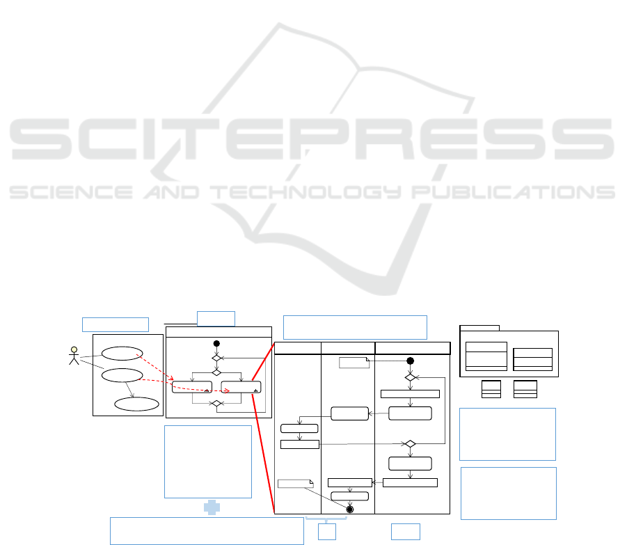
Figure 1 shows an outline of the requirements
analysis model. At first, candidates of basic functions
satisfying the main service goal are extracted and
realized as a use case diagram. Several scenarios are
then defined by combining these use cases in an
activity diagram. Defining a scenario means having
an activity diagram expressing how to use the system
through the relationships between the use cases
depicted in the specified use case diagram; the use
case diagram can include sub-activity nodes that
correspond to the use cases.
Generally, a use case description consists of an
actor, preconditions, postconditions, and normal and
exceptional action flows or paths. To make the
description more formal and observable, we define a
use case description using an activity diagram. As
each use case is defined by an activity diagram, a
scenario can be interpreted as the entire set of action
flows obtained by expanding all sub-activity
diagrams.
In addition to normal and exceptional action flows
with guard conditions, activity diagrams can also
specify data flows that are related to these actions;
this can help provide for a more intuitive
understanding of the use case. Actions are defined by
action nodes, whereas data are defined by object
nodes, which are classified as members of a class
defined in a class diagram. Accordingly, these two
kinds of diagrams enable us to specify application
processing paths in connection with the data. In
particular, the interaction between a user and a system
includes both the requisite execution paths and the
data used to satisfy user input, output, and any
conditions required to correctly execute a use case.
Figure 1: UML Requirements Analysis Model.
Actor
System
Usecase1
Usecase2
Usecase3
<<include>>
System
Usecase1 Usecase2
Use case description
• Actor
• Pre-condition
• Normal flow
• Exceptional flow
• Post-condition
Clarify a boundary between a user and a system.
Clarify a role of an action and data.
Logic
Data
is referred from an actin
|is created by an action
|is deleted by an action
|is updated by an action
Guard
Is conditioned on data
| is a relational expression
between attributes
| is data invariant
SystemInte ractionUser
Action in System
Re q uest Inpu t
Action
Inp u t Action
Output Action
Action in System
[mormal ]
[exceptional]
Reference Object : ClassA
Created Object : ClassB
pre-condition
post-condition
Inp u t Ite m : In put
Output Item : Outpu t
Input Output
Entity Data
- field3 : String
ClassB
- field2 : String
- field1 : Integer
ClassA
UI
Use case
is a sequence of actions given each role.
Use case diagram
Scenario
Automatic Verification of Behavior of UML Requirements Specifications using Model Checking
159
The second feature of this model is that an activity
diagram has three types of partitions: user,
interaction, and system. These partitions enable the
ready identification of the following activities: user
input, any user-system interaction caused by
attempting to satisfy the conditions required for
executing a use case, and system output. Object nodes
in the user, interaction, and system partitions
represent input data, output data, and entity data,
respectively. Therefore, the parts of system behavior
concerned with processing or logic can be separated
from the parts concerned with presentation. The
requirement analysis model is defined using a
modeling tool named astah* (the asterisk is included
in the name); this was done to make it easier to
develop support tools used for model driven
development.
Use cases are a fundamental component used in
defining functional requirements. However, as
mentioned above, non-functional requirements such
as those pertaining to hardware architecture, system
safety, and user characteristics can strongly affect use
case composition or make up. As we have presented
previously (Matsuura, 2018), it is important to
implement an iterative cycle of analysis and
verification through which the requirements
specification of a system is defined incrementally. A
use case model is useful for defining the expected
behavior of a system by considering the combination
of use case candidates; however, it is difficult to
confirm the concurrent behaviors of multiple systems,
interacting with each other, by only utilizing a static
model in UML.
2.2 Problems with UML Modeling of
Interactions across Multiple
Systems
In UML, an actor specifies a role played by a user or
any other system that interacts with the subject. In a
use case, the actors within a system are related; the
services of the system are provided by other external
systems such as hardware including various sensors
or actual people with different roles. All scenarios for
satisfying a system goal should be specified by the
interactions involving a subset of these actors.
We define this interaction by an activity diagram,
called a workflow, as follows.
A workflow specifies one or more user scenarios
in which several actors interact with each other with
the object of satisfying the system goal by dividing
partitions. Each partition describes the behavior of an
actor, that is, a subsystem or user with a role, by
considering action and data flows.
A workflow focuses on passing the data on the
boundaries of each subsystem to extract the
subsystem inputs and outputs required for specifying
the interactions between subsystems and users. To
completely specify the interactions occurring at the
boundary between two subsystems, it is necessary to
determine what data to send to whom and what data
to receive from whom. Thus, data passing actions in
a workflow on the boundary are denoted by a pair of
signal-sending and signal-receiving nodes, as shown
in Figure 2. Moreover, the destination of data sent and
received is denoted by the UML stereo type, and a
label of the action node is needed to represent a class
of data. The inherent action of the subsystem is
denoted by a typical action node, and its detailed
behavior is described by an activity diagram, as
shown in Figure 1.
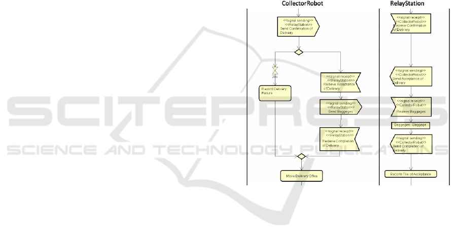
Figure 2: Nodes for interaction between different
subsystems.
Figure 2 shows an example of the interaction
between two subsystems, named Relay Station and
Collector Robot, in which Collector Robot sends a
signal to Relay Station and acts according to the
presence or absence of a response from Relay Station.
In this case, a clock event receipt action is used to
denote the condition that Collector Robot is unable to
receive a response from Relay Station within 20
seconds.
To verify that a workflow satisfies the system goal,
all relevant subsystems should interact as required
and exchange the data required for each task to be
processed. Therefore, at this stage, the relevant
interactions between all subsystems and the data
required to accomplish the above goal should be
defined in the model.
MODELSWARD 2020 - 8th International Conference on Model-Driven Engineering and Software Development
160
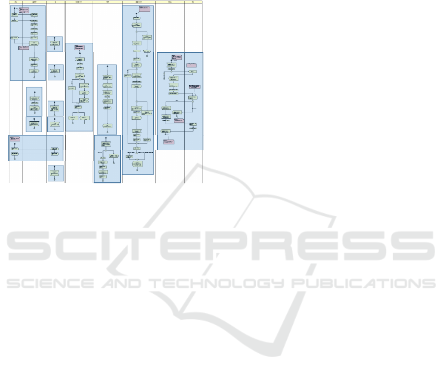
After verifying that the workflow satisfies the
system goal, we can derive a use case diagram from
the partition corresponding to the subsystem in the
workflow, as shown in Figure 3. The shaded parts
represent the use cases for each subsystem.
Figure 3: Extraction of use cases from a workflow model.
In UML, a label is written for each node in a
natural language. This has the advantage of being
easy to model for many general software engineers.
However, this acts as a double-edged sword; a model
that is easy to understand may be ambiguous or
contain inconsistencies. Moreover, an activity
diagram is a general purpose model for describing
behavior. In UML, there is no predefined set of
symbols available for defining a workflow; moreover,
we cannot describe the timing that is required to
activate multiple action flows within a workflow.
As mentioned above, expressing an action of data
passing as a symbol, as shown in Figure 2, is useful
for enhancing the readability of a model. Reviewing
the model may resolve the issue of ambiguity, but the
difficulty of resolving the issue of inconsistency
remains. Another difficulty is that if an action of the
subsystem inherently includes actions that result in
interaction with other subsystems, we must verify this
interaction by providing details of this behavior in the
activity diagram.
A workflow must be verified to determine
whether it meets the system goal. However, it is
difficult for a workflow model written in UML to be
directly verified for correctness, because the parallel
behaviors observed with multiple systems operating
concurrently cannot be simulated within UML.
Model checking is a useful and automatic verification
technique for a system featuring parallel behavior; it
exhaustively and automatically checks whether the
model meets a given specification. By mapping a
workflow in UML to some abstract model checking
behavioral model, we can verify properties such as
liveness, reachability, safety, and fairness. To resolve
these problems, we discuss how to use the model
checking tool UPPAAL in the next section.
3 A VERIFICATION METHOD OF
STATIC UML MODELS
In the verification of our model, we consider the
timing of actions involving the sending and receiving
of data within the activity diagram, and the fidelity of
the target, as the factors responsible for the
synchronization between the respective subsystems.
We also confirm that multiple systems can complete
a task without stoppage. To utilize the advantages of
the model, we propose a method of verifying the
cooperative behavior of a UML requirements analysis
model by transforming it into an UPPAAL model.
3.1 The Model Checking Tool
UPPAAL
The model checking tool UPPAAL uses temporal
logic to model the system as a network of automata
that is extended with integer variables, structured data
types, user-defined functions, and channel
synchronization. Based on these properties, a system
model and query expressions can be defined to
specify which properties are to be checked. When the
specified properties are not found to be compliant, the
tool provides counterexamples that demonstrate how
the model should be improved. The simulator helps
to detect defects caused by tracing the processes in
which the counterexamples are found to occur. The
model checking technique automatically verifies a
model by exhaustively checking all paths to search
for and detect properties that developers often
overlook.
UPPAAL has a graphical editor for editing a
model and a verifier for verifying the specified model
through query expressions using temporal logic.
Moreover, it has a simulator used to check for failures
of the model in a systematic manner. An edited model
writes output to a file in XML format. Figure 4 shows
that the UPPAAL model consists of several locations
and of transition arrows between them. A location
expresses a system state; a transition arrow indicates
several conditions: one named Guard, and one named
Update for sequential processing events that may
occur. Figure 4 shows START, LOC1, and LOC2 as
Automatic Verification of Behavior of UML Requirements Specifications using Model Checking
161
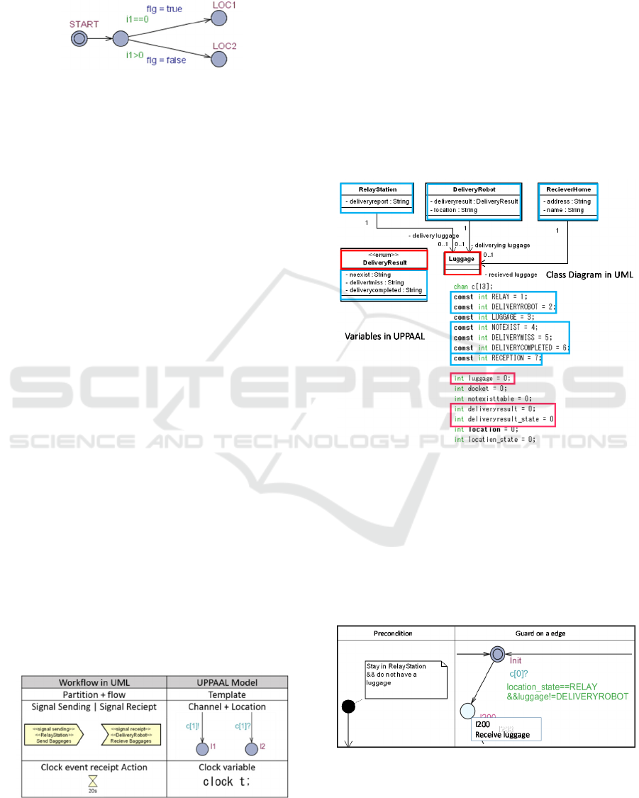
the names of each location. “i1==0” and “i1>0” are
Guard expressions, and “flg=true” and “flg=false”
represent the Update expressions.
Figure 4: Basic components of the UPPAAL model.
3.2 Model Transformation Rules
The UPPAAL model consists of multiple processes,
which are created from a template containing several
parameters. Each process is an instance subject to the
multiple system behaviors that are observed to occur
concurrently.
A workflow is a scenario that is constructed by
combining use cases to satisfy the goal of a system.
Moreover, we can see it as a state transition in which
nodes are connected by flows. Preconditions and
postconditions provide some constraints on the
combinations of use cases. In UML, preconditions,
postconditions, action node labels, and guard
conditions in the activity diagram are defined in a
restricted natural language. Here, the meaning of the
word "restricted" is that these can be defined through
components (i.e., class names or attribute names) in a
class diagram because it defines the data appearing in
a workflow. This makes it possible to identify not
only the node position but also the state as represented
by preconditions, post conditions, action node labels,
and guard conditions.
Meanwhile, the UPPAAL model is also a model
representing state transitions in which the locations
are connected by edges. States are represented by
expressions using locations and variables. We thus
define the correspondence between UML model
elements and UPPAAL model elements as shown in
Table 1. Consequently, the flow of the node in a
workflow is mapped to the flow of the location in
UPPAAL.
Table 1: Correspondence between the two type models.
By analyzing class attributes and the association
between these classes in a class diagram as shown in
Figure 5, preconditions, postconditions, action nodes
labels, and guard conditions in a workflow are
translated into expressions defined by variables
within UPPAAL. This class diagram defines data that
is referred to within the workflow. As a workflow
expresses cooperation between subsystems or users,
the class diagram includes a class corresponding to a
subsystem. A class referred by a subsystem means an
object whose state changes within a workflow during
task processing; the class expresses a variable and
each subsystem becomes this value. An enumeration
class defines constant values in the workflow.
Figure 5: Correspondence between elements in a class
diagram in UML and variables in UPPAAL.
As action node label descriptions, preconditions, and
postconditions essentially have a simple syntax such
as "object + verb," and a construct such as "object" is
defined by a component in a class diagram, an
expression in an UPPAAL model can be generated
through natural language processing. Figure 6 shows
an example of this translation.
Figure 6: An example of mapping preconditions to
expressions.
MODELSWARD 2020 - 8th International Conference on Model-Driven Engineering and Software Development
162
In this study, we verify, for a specific behavior,
the correctness of the interactions occurring between
all subsystems, by focusing on the data passing that
occurs between these subsystems. The specified
behavior of a subsystem is defined by a sequence of
actions within a workflow, in the corresponding
partition. A component in the set is transformed into
a template. Each signal sending and signal receiving
node is transformed into a location with a channel
identified by the label of the node. When a pair of
subsystems, denoted by a stereotype and an object in
the label, has the same name in a pair of signal
sending and signal receiving nodes, the same channel
is used in the transformed model.
Here, the term fidelity means that the specified
system will never experience deadlock. Thus, a query
expression used for this verification is A[](not
deadlock). Therefore, it is possible to check whether
there is a state into which any process cannot be
transitioned into, irrespective of the length of the
execution path.
Describing a system in an UPPAAL model makes
it possible to verify parallel or concurrent behavior.
However, as UPPAAL is defined by a focus on state
transitions of the system, it is not suitable for
describing workflows that focus on the required
procedures of each subsystem.
3.3 An Automatic Model
Transformation Tool
We have implemented a tool that automatically
transforms the UML model into an UPPAAL model;
the tool also makes it possible to confirm that
deadlock will never occur in the specified system
using the UPPAAL verifier. This tool is developed for
Java and the astah* API.
Figure 7: The source UML model and the transformed
UPPAAL Model.
UPPAAL has a graphical user interface in the
editor and simulator, but the transformed model
requires visual capabilities. Thus, our automatic
transformation tool can generate graphs that are easy
to visualize by positioning the same coordinates used
in the source UML model, as shown in Figure 7.
When the specified properties are not satisfied, the
tool provides counterexamples that demonstrate how
the model should be improved. The UPPAAL
simulator is useful for analyzing defects of the model.
A process of modeling and verifying the behavior
in the interactions of multiple systems is described as
follows.
1) A workflow model is defined using the UML
modelling tool astah*.
2) The automatic model transformation tool is
deployed, and the above astah* file is selected.
A tool generates an XML file to be input into the
UPPAAL tool, and a table listing the
correspondence between elements of the UML
and UPPAAL models is generated. When a
workflow includes an action corresponding to a
use case that includes a signal sending and
receiving action to/from other subsystems, the
action flow in the use case is expanded in the
UPPAAL model.
3) The UPPAAL tool is run, the generated XML
file selected, and the query expression A[](not
deadlock) is entered in the input box of the
verifier. The verifier tool exhaustively checks all
execution paths of the model.
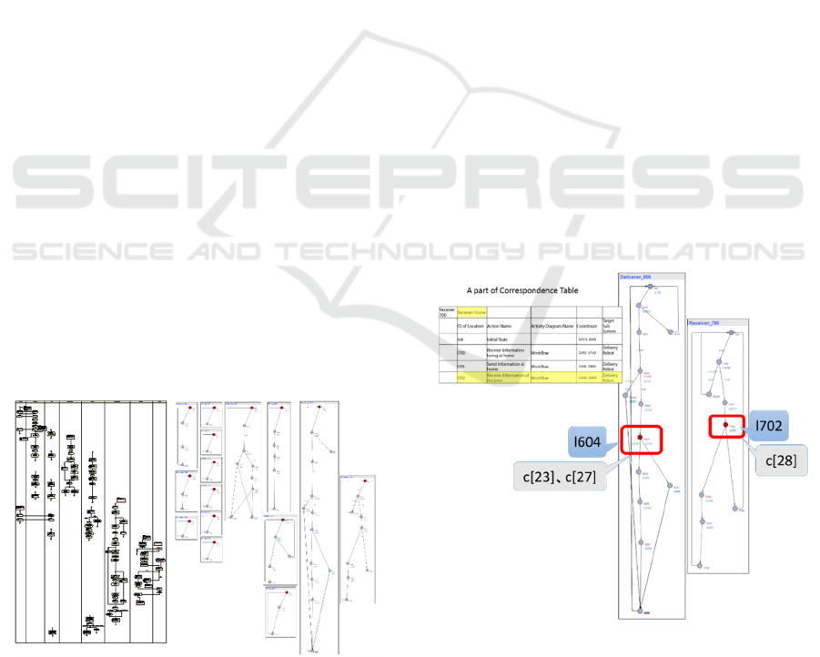
Figure 8: Finding defects through counterexamples.
4) The tool then provides the results. In the case
where the message “The property was satisfied.”
is displayed in green characters, the tool assures
that there are no problems with the model. In the
Automatic Verification of Behavior of UML Requirements Specifications using Model Checking
163
case where the message “The property was not
satisfied.” is displayed in red characters, the
simulator is then executed, and the provided
counterexamples are displayed that show how
the model should be improved. The simulator
shows issues that cause deadlock in red symbols,
as shown in Figure 8. We can see sequence
charts and the automatic model in a systematic
manner.
5) According to the correspondence table
mentioned in 2), we can examine the points that
suggest improvements in the source UML
model, as shown in Figure 8.
3.4 Case Study
We conducted an experiment to verify an automatic
luggage transfer system that is a problem-based
learning (PBL) subject in our university. In this
system, two autonomous vehicle type robots play the
roles of luggage collection and delivery under a given
set of circumstances and conditions. There are 14
requirements for delivery service, consisting of 6
subsystems and 2 users. The two robots and the relay
station are implemented using LEGO
MINDSTORMS EV3. The delivery reception office,
the recipient home, and the head office for managing
the records of luggage transfer are implemented by a
PC. Luggage transfer information between
subsystems is exchanged by communications over
Bluetooth.
The model on the left side of Figure 7 is the
workflow defined by the group of students in this
PBL experiment; on the right side is the generated
UPPAAL model. As mentioned in Section 3.3, we
verified whether multiple paths could be run in
parallel, without encountering deadlock, in the
generated model.
Here in this model, a deadlock has occurred.
Figure 8 shows a counterexample for the query
expression A[](not deadlock). Communications
between the process Deliverer_600 and the process
Receiver_700 was halted at the point indicated by the
red symbol. We can see that there is no receiver
channel for transmissions on channel c[28] and no
transmissions for reception on channels c[23] and
c[27]. As transmission and reception on a channel
correspond to signal sending and signal receiving
nodes in the UML model, synchronizations done via
channel should be defined by a pair of signal sending
and signal receiving nodes.
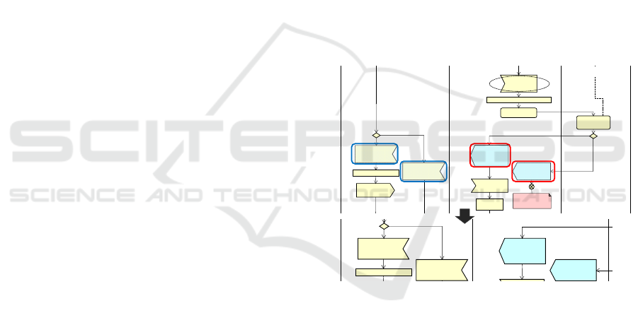
As Figure 10 shows, we can look for defects in the
UML model. First, from the correspondence table, we
find the element "Receive information of Receiver"
of the UML model corresponding to l702 and look at
the signal transmission node following it. As part of
this inspection, we confirm the correctness of data
exchange across subsystems; subsystem-specific,
actor actions, and object nodes are not transformed
into the UPPAAL model during the tool
transformation process, because they are not relevant
to the communication rules. We can thus specify this
selection through the tool’s options. Next to the red
location is the channel c[28], but the corresponding
position in the UML model describes two signal
sending nodes (i.e., nodes surrounded by red lines in
Figure 9). However, it turns out that this was
transformed into a single channel, because both have
the same label. Furthermore, it was found that the
labels of both corresponding signal receiving nodes
are incorrect; they are surrounded by the blue line in
Figure 9.
After correcting the label of one signal sending
node as shown in Figure 9, a new UPPAAL model is
generated and we can confirm that deadlock does not
occur.
Figure 9: Finding and correcting defects in the UML
workflow model.
4 DISCUSSION
A workflow includes subsystem specific actions that
are refined as use cases for the subsystem. Such use
cases sometimes require cooperation with other
subsystems; in this case, use case descriptions can be
expanded to inspect the expanded interactions
between subsystems that are observed.
UML is widely recognized as a general-purpose
modelling language. There is a problem however, in
that UML does not lend itself easily to formal
verification; UML does not have strict formal
semantics. Many studies have therefore been
<<Reciever Home>>
<<signal receipt>>
Recieve about reciever
corre ctne ss
Delievery Baggage : Baggage
<<Reciever Home>>
<<signal receipt>>
Recieve about reciever
incorrectness
<<Delivery Robot>>
<<signal sending>>
Send about reciever
correctness
[
correc
t]
<<Delivery Robot>>
<<signal sending>>
Send about reciever
incorrectness
<<Reciever H ome>>
<<signal receipt>>
Recieve about reciever
correctness
<<Reciever H ome>>
<<signal sending>>
Send Baggeges
Delievery Baggage : Baggage
<<Reciever H ome>>
<<signal receipt>>
Recieve about reciever
incorrectness
<<Delivery Robot>>
<<signal sending>>
Send about reciever
correctness
<<Delivery Robot>>
<<signal receipt>>
Recieve Baggages
Confirm reciever
information
<<Delivery Robot>>
<<signal receipt>>
Recieve reciever
information
[incorrect]
[correct]
Reciever Information : PersonalInformation
Delivery
Baggege :
Baggage
<<Delivery Robot>>
<<signal sending>>
Send about reciever
correctness
Post conditions:
・Do not recieve the
baggages.
Confirm reciever
Inform ation
Reciever Home
l702
Reciever
Delivery Robot
MODELSWARD 2020 - 8th International Conference on Model-Driven Engineering and Software Development
164

conducted that convert UML models into formal
languages that can be used for verification.
Several studies (Bose, 1999 and Jing, 2009) have
proposed methods to transform UML models into
Process or Protocol Meta-language (PROMELA) for
use with the model checking tool SPIN. However,
developers are required to directly operate the model
checking tool; a knowledge of both UML and SPIN
is thus necessary. Our approach has the advantage
that parallel behavior, which is difficult to confirm in
a static UML model, can be verified.
The assignment of accurate meanings to UML
activity diagrams by utilizing CSP has been proposed
(Xu, 2009). However, even if a model becomes
verifiable due to the strict nature in which its
description is performed, the process of determining
requirements in the requirements analysis stage may
be difficult for general developers to follow because
of its demands on strictness.
The necessity of preventing state explosion that
arises from using a model checking tool has been
discussed (Eshuis, 2004). This is an important
problem to be solved, if model checking is to be used
as a part of practical development. However, it is
necessary to consider the model transformation
method, which depends on the items that need to be
verified. In this paper, we reduce the number of nodes
by focusing on inspection items concerned only with
data exchanges performed by the signal sending and
receiving nodes of a workflow. Additionally, to
reduce the number of inspection paths, items defined
in a class diagram are transformed to variables in the
UPPAAL model; this helps to avoid the issue of
unnecessary inspection paths.
The dynamic aspects of UML class diagrams,
state machine diagrams, and collaboration diagrams
using the system description language Maude was
verified (Mokhati, 2007). These studies are aimed at
transforming UML models into formal languages and
verifying the dynamic aspects of the system. As a
starting point however, the questions of what can be
defined in in a UML model and how this can be done
is not discussed. There are functional and non-
functional requirements; non-functional requirements
have a large impact on the initial model, and the
quality of service provided by the system can change.
Therefore, as discussed in the Twin Peaks Model,
requirements specifications must be defined while
checking non-functional requirements in this stage.
We think that it is important to formalize the
requirements component in line with items that can
be verified, along with the process of requirements
analysis.
5 CONCLUSION
The initial system model is dependent on the features
of non-functional requirements, because these
features may restrict or expand the content of the
service. Therefore, the quality of the generated source
code is affected by these source models; these models
may contain concerns that are potentially ambiguous
and need to be identified within the requirements.
Initial specifications require systematic elaboration
while considering these features, as discussed in the
Twin Peaks Model. It is also important that non-
functional requirements such as hardware
architecture are verified in the early stages of
development.
To verify the dynamic aspects of requirements
specification, this paper presented the effective
combination of the modeling language UML with the
model checking tool UPPAAL, performed at an early
stage of system development. We applied this method
to a requirements analysis example involving a
multiple cooperative system. It was able to confirm
that the exchange of data performed during the
interoperation of two or more systems; in contrast,
this process of confirmation is difficult to perform
through appropriate review of UML models.
REFERENCES
Nuseibeh, B., 2001, Weaving the Software Development
Process Between Requirements and Architectures,
IEEE Computer, 34(3), pp.115-117.
OMG,” UNIFIED MODELING LANGUAGE”,
http://www.uml.org/
UPPAAL, http://www.uppaal.com/.
Jacobson, I., M. Christerson, P. Jonsson, and G. Övergaard,
1992, Object-oriented software engineering: A use case
driven approach, Addison-Wesley Publishing.
Ogata, S. and S. Matsuura, 2010, A Method of Automatic
Integration Test Case Generation from UML-based
Scenario,” WSEAS TRANSACTIONS on
INFORMATION SCIENCE and APPLICATIONS,
Issue 4, Vol.7, pp.598-607.
Aoki Y., S. Ogata, H. Okuda and S. Matsuura, 2012,
Quality Improvement of Requirements Specification
Using Model Checking Technique, Proc of ICEIS 2012,
Vol.2, pp.401-406.
astah*, http://astah.net/
Matsuura, S., S. Ogata and Y. Aoki, 2018, Goal-
Satisfaction Verification to Combination of Use Case
Component, ENASE2018, pp.343-350.
Bose, P., 1999, Automated translation of UML models of
architectures for verification and simulation using
SPIN, Proc. of the ASE, pp.102-109.
Automatic Verification of Behavior of UML Requirements Specifications using Model Checking
165

Jing, L., L. Jinhua, and Z. Fangning, 2009, Model Checking
UML Activity Diagrams with SPIN, Proc. of the CiSE
2009, pp.1-4.
Xu, D., Miao.H., and Philbert, N., 2009, Model Checking
UML Activity Diagrams in FDR+, 2009 Eighth
IEEE/ACIS ICCIS,pp.1035-1040.
Eshuis, R. and Wieringa, R., 2004, Tool Support for
Verifying UML Activity Diagrams, IEEE
TRANSACTIONS ON SOFTWARE ENGINEERING,
VOL. 30, NO. 7, pp. 437-446.
Mokhati, F., Gagnon P., and Badri M.,2007, Verifying
UML Diagrams with Model Checking: A Rewriting
Logic Based Approach, QSIC 2007, pp. 356 – 362.
MODELSWARD 2020 - 8th International Conference on Model-Driven Engineering and Software Development
166
