
Towards Interoperability of oneM2M and OPC UA
Salvatore Cavalieri
a
and Salvatore Mulè
Department of Electrical Electronic and Computer Engineering, University of Catania, Catania, Italy
Keywords: Interoperability, OPC UA, oneM2M, Industry 4.0.
Abstract: Interoperability between industrial applications is considered a cornerstone in the current fourth industry
revolution, known as Industry 4.0. Interoperability can be realised in different ways, among which by
interworking solutions between existing communication systems adopted inside Industry 4.0. Among them
there are oneM2M and OPC UA. To the best of the authors’ knowledge, literature does not present
interworking solutions between these two communication systems. For this reason, the paper proposes and
describes a novel solution to realise the interworking between OPC UA and oneM2M.
1 INTRODUCTION
Since few years, industry has been involved in a
revolution, the fourth one, which has been coined
with different names in different countries; one of the
most known is Industry 4.0. It features the application
of modern Information and Communication
Technology concepts in industrial contexts to create
more flexible and innovative products and services
leading to new business and added value models
(Liao, Deschamps, Loures and Ramos, 2017), (Xu,
Xu and Li, 2018).
Realisation of this novel vision may be achieved
only if a big effort is really put to make interoperable
the interchange of information between industrial
applications (Weyer, Schmitt, Ohmer and Gorecky,
2015). Interoperability can be realised in different
way (European Telecommunications Standards
Institute, 2017); one of the possibilities is represented
by interworking solutions between the existing
communication systems adopted inside Industry 4.0.
During the last few years, different organisations
have developed reference architectures to align
communication systems in the context of the fourth
industrial revolution. Among them, there is the
Industrial Internet Reference Architecture (IIRA) by
the Industrial Internet Consortium (IIC), (Industrial
Internet Consortium, 2017). IIRA defines several
solutions available today for getting data between
applications. In the IIRA document (Industrial
Internet Consortium, 2018), these solutions are
a
https://orcid.org/0000-0001-9077-3688
broken down into two categories: transports and
frameworks. The distinguishing difference between
them is the fact that a framework includes a capability
for maintaining and enforcing a data model that is
used by the applications participating in the
framework. The frameworks identified by IIRA are:
OPC UA (Mahnke, Leitner and Damm, 2009),
oneM2M (oneM2M TS-0001, 2019), Data
Distribution Service (DDS) (Object Management
Group, 2015) and Web Services (W3C, 2004).
On account of what said before, interoperability
among these IIRA frameworks seems very important
in the context of Industry 4.0. For this reason,
interworking solutions of this kind are starting to
appear in the current literature. The first proposal
towards this direction, is represented by a very recent
draft version of the gateway between OPC UA and
DDS, defined by (Object Management Group, 2019);
in this case, the interworking solution defines a
mapping between OPC UA data model and the data
space of the DDS system.
To the best of the authors’ knowledge, literature
presents only another interworking approach
involving IIRA frameworks; they are OPC UA and
oneM2M. Technical report (oneM2M TR-0018,
2018) introduces a very preliminary work about the
mapping from OPC UA data model towards oneM2M
but not in the opposite direction. The document only
aims to point out the main limitations of the current
version of oneM2M standard to realise this mapping
and the relevant possible solutions to enable it. It is
Cavalieri, S. and Mulè, S.
Towards Interoperability of oneM2M and OPC UA.
DOI: 10.5220/0009328007050714
In Proceedings of the 22nd International Conference on Enterprise Information Systems (ICEIS 2020) - Volume 1, pages 705-714
ISBN: 978-989-758-423-7
Copyright
c
2020 by SCITEPRESS – Science and Technology Publications, Lda. All rights reserved
705

important to point out that a real interworking
solution is not given in this document. Furthermore,
the study presented in (oneM2M TR-0018, 2018)
only deals with the interworking from OPC UA
towards oneM2M; exchange of information in the
opposite direction is not considered at all. No other
documents about interworking between OPC UA and
oneM2M are present in the current literature.
On account of what written, the paper proposes a
novel solution to realise the interworking between
OPC UA and oneM2M. Due to the presence in
literature of the technical activity about the
interworking from OPC UA to oneM2M described in
(oneM2M, 2018) (although the activity is only a
feasibility study at a very early stage), the authors
have decided to limit their contribution to the
interworking in the opposite direction, i.e. from
oneM2M to OPC UA. The approach presented will be
described in the remainder of this paper, after a brief
overview about OPC UA and oneM2M.
2 OPC UA OVERVIEW
OPC UA is an international standard, IEC 62541,
mainly based on a client/server communication
model allowing distribution to OPC UA Clients of
information maintained by an OPC UA Server
(Mahnke et al., 2009).
The set of information is maintained through OPC
UA Nodes grouped together to compose the so-called
AddressSpace. Each OPC UA Node belongs to a class
named NodeClass. Among the available classes there
are Variable and Object, created inside the
AddressSpace as instances of other OPC UA Node
Classes called VariableType and ObjectType,
respectively.
OPC UA offers many services to allow an OPC
UA Client to access the AddressSpace of OPC UA
Servers (OPCFoundation, 2017). The simplest way to
allow an OPC UA Client to explore the AddressSpace
of an OPC UA Server is using the OPC UA Browse
Service.
The OPC UA Read service is used to read one or
more attributes of Nodes. OPC UA Client invoking
the OPC UA Read Request may specify a maxAge
parameter (expressed in milliseconds). Briefly, the
maxAge parameter is used to force the OPC UA
Server to access the requested value directly from the
underlying data source, if the “age” of the current
value maintained in the AddressSpace is greater than
the maxAge. The age of the value is based on the
difference between the ServerTimestamp (i.e. the
time at which the local data has been stored in the
local AddressSpace) and the time when the Server
starts processing the request. More details about the
procedures performed by OPC UA Server to handle
maxAge parameter will be given in Section 5.3.
The Write service allows the writing of one or
more attributes of one or more Nodes. The values are
generally written to the data source; the OPC UA
Server will report if it succeeds in the write operation.
Depending on the particular implementation, the OPC
UA Server may write to an intermediate system and
the data source will be updated by using other
mechanisms external to the standard. In these cases,
the OPC UA Server should report a success code that
indicates that the writing operation on the data source
was not verified.
Subscriptions and MonitoredItems represent a
more sophisticated way to exchange data between
OPC UA Client and Server. They allow an OPC UA
Client to receive cyclic updates of OPC UA Variable
values and Node attributes. A Subscription is the
context needed to realise this cyclic exchange of
information; MonitoredItems must be created inside
a Subscription by the OPC UA Client and must be
associated to OPC UA Nodes. The
CreateSubscription and CreateMonitoredItem
Services allow an OPC UA Client to create a
subscription inside an existing Session and a
MonitoredItem inside an existing Subscription,
respectively.
MonitoredItems have several settings among
which there is the SamplingInterval which defines the
rate at which the OPC UA Server checks for changes
in the associated Node, e.g. changes of the values for
Variable Nodes and/or of the attributes for Object
Nodes. If a change is detected, each MonitoredItem
produces a particular message, called Notification,
whose content depends on the changes detected; for
example, in the case of changes of OPC UA Variable
value, the parameter contains the new value updated.
Notifications are put in a queue defined inside each
MonitoredItem. Size and queuing policy may be
defined by the OPC UA Client for each
MonitoredItem queue.
Each Subscription features a PublishingInterval,
which defines the interval at which the OPC UA
Server clears all the MonitoredItem queues contained
in the Subscription and conveys their contents (i.e.,
Notifications) into a NotificationMessage to be sent
to the OPC UA Client. Transmission of
NotificationMessages by OPC UA Server is triggered
by Publish requests and responses exchanged
between OPC UA Client and Server.
ICEIS 2020 - 22nd International Conference on Enterprise Information Systems
706
3 oneM2M OVERVIEW
oneM2M communication system provides
interoperability support for M2M (machine-to-
machine) and IoT technologies, through a platform
architecture based on three layers: Application,
Common Services and Network Services.
In the oneM2M functional architecture, the
following basic types of entities are defined for each
layer (oneM2M TS-0001, 2019). Application Entity
(AE) is defined as an entity in the Application layer
implementing a M2M application service logic.
Common Services Entity (CSE) represents an
instantiation of a set of Common Service functions.
Network Services Entity (NSE) provides
communication services from the underlying network
to the CSEs.
Communication flow between entities is
supported by the so-called reference points. Mca
enables communication between AE and CSE. Mcc
enables communication between CSEs. Mcn has been
defined for the communication flow between a CSE
and the NSE; it allows a CSE to use the supported
services provided by the NSE.
Nodes are logical entities identifiable in oneM2M
System, typically containing CSEs and/or AEs
(oneM2M TS-0001, 2019). In the following, an
overview on the main types of nodes defined in
oneM2M will be given.
Application Dedicated Node (ADN) is a node that
contains at least one AE and does not contain a CSE.
An ADN would typically be implemented on a
resource constrained device. AE contained in an
ADN is named ADN-AE.
Middle Node (MN) is a node that contains one
CSE (i.e. MN-CSE) and could contain AEs (i.e. MN-
AE). Typically, a MN would reside in an oneM2M
Gateway (which is capable to map operations on
oneM2M world into non-oneM2M world). MN
would be used to establish a logical tree structure of
oneM2M nodes containing AEs and requiring
communication services from CSE included in the
MN.
Infrastructure Node (IN) is a node that contains
one CSE (i.e. IN-CSE) and could contain AEs (i.e.
IN-AE). A IN containing a CSE is typically hosted in
the cloud to improve remote accesses.
Non-oneM2M Node (NoDN) is a node that does
not contain oneM2M entities. Such nodes represent
devices attached to the oneM2M system for
interworking purpose.
Common Services layer provides many services
(one M2M TS-0001, 2019); in the following, the
authors will focus only on these allowing
representation and management of resources
(Resource Management services). Three categories of
resources are defined; they are the Normal Resources
(which includes the complete set of data
representation), Virtual Resources (which don’t have
permanent representation, and used to trigger
processing or retrieve result) and Announced
resources (aiming to simplify resource discovery,
used to link original resource). In the following,
description of resources will focus only on the
Normal one.
Many resource types are defined in oneM2M for
the Normal resource category; each of them is made
up by set of mandatory and optional attributes and
may be the root of a resource tree of the so-called
child resources. Each attribute is uniquely
addressable and manipulated using CRUD
operations. According to the current version of the
oneM2M specifications, CRUD operations may be
realised by HTTP methods.
Among the available Normal resource types,
there is the <AE> resource, which represents
information about an Application Entity registered to
a CSE.
The concept of subscription to resource instances
in order to receive notifications about content changes
is also specified in oneM2M; it allows efficient
monitoring of resource instances and thus of the
exposed resources. In particular, the resource defined
as <subscription> contains subscription information.
It is represented as a child-resource of the subscribed-
to resource, and it contains information about the
subscriber and notification policies. Create
<subscription> request service is used to create such
resource.
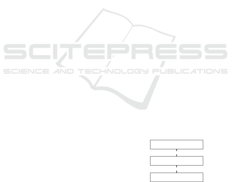
In order to enhance interworking, oneM2M uses
specialised interworking application entities called
Interworking Proxy application Entity (IPE). An IPE
is an AE that supports both oneM2M Mca reference
point as well as the non-oneM2M interface, as shown
by Figure 1 (oneM2M TS-0033, 2019).
CS E
IPE
NoDN
Mca
non oneM2M interface
Figure 1: IPE and relevant interfaces.
Definition of an IPE requires the determination of
native oneM2M services (e.g. oneM2M resource
instances) to be exposed to the non-oneM2M system.
Towards Interoperability of oneM2M and OPC UA
707
Furthermore, the dynamic management of oneM2M
services exposed in IPE must be supported; when
changes occur in oneM2M system, these changes
must be reflected in the non-oneM2M system and
vice versa.
4 INTERWORKING PROPOSAL
As said in the Introduction, this paper presents an
interoperability proposal between oneM2M and OPC
UA, based on the definition of an interworking
scheme from oneM2M to OPC UA.
The interworking solution presented in the paper
has been based on the use of the IPE defined by
(oneM2M TS-0001, 2019) and (oneM2M TS-0033,
2019). In particular, the proposal defines an IPE
architecture, called in the following OPCUA-IPE.
The design of the OPCUA-IPE is based on the
assumption made by the authors to use an OPC UA
Server to expose the resources belonging to oneM2M
system towards the OPC UA system. OPC UA
Clients may connect to the OPC UA Server offered
by OPCUA-IPE through OPC UA interfaces;
accessing the information maintained by the OPC UA
Server, means accessing to the relevant resources
present in the oneM2M system.
In the remainder of this section, an overview of
the OPCUA-IPE will be given.
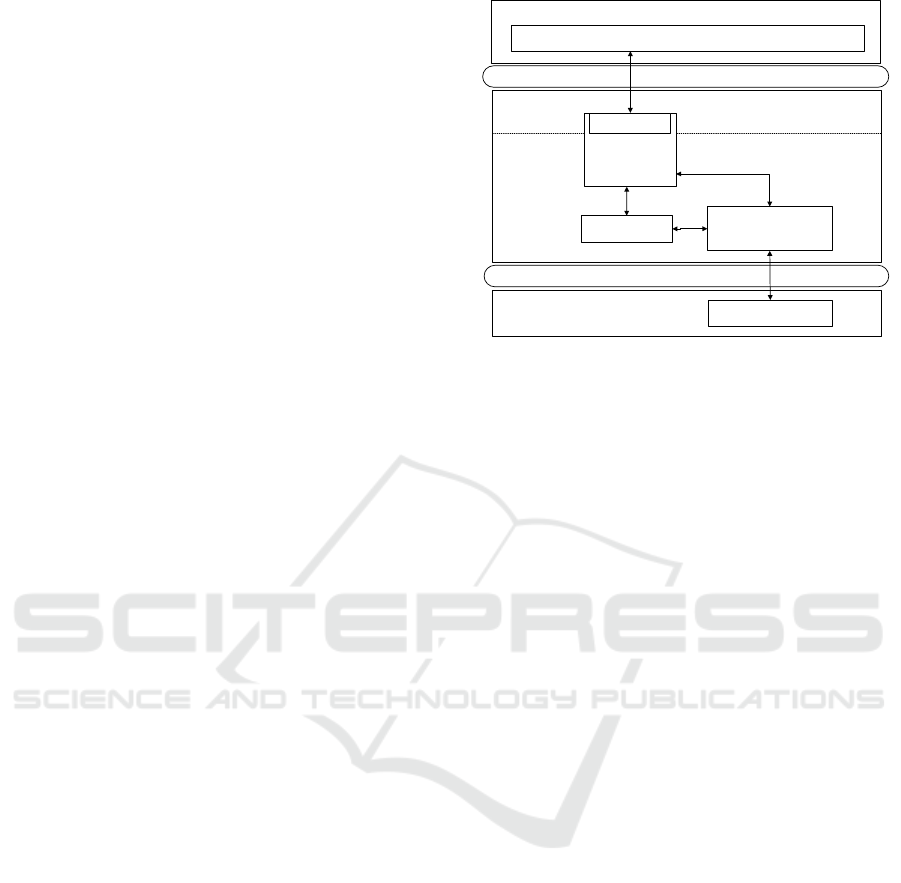
4.1 Design of OPCUA-IPE
Figure 2 shows the OPCUA-IPE proposed. It is based
on the IPE architecture shown by Figure 1. Three
main entities are present: an instance of OPC UA
Server, the Data Cache and the Interworking
Manager.
The instance of the OPC UA Server contains the
AddressSpace maintaining Nodes mapping the
oneM2M resources to be exposed towards the OPC
UA system. It has been assumed that each oneM2M
resource may be represented by a suitable OPC UA
Node inside the OPC UA AddressSpace; a mapping
procedure defined by the authors, is applied in order
the attributes of each OPC UA Node may reflect the
relevant attribute of the original oneM2M resource.
Each time a change occurs in an oneM2M resource
exposed, the same change must be reflected in the
relevant OPC UA Node inside the OPC UA Server.
In the opposite direction, each change inside the
AddressSpace must be reflected in the correspondent
oneM2M resource. Mapping between oneM2M
resources and OPC UA Nodes is fundamental in this
proposal and it will be described in subsection 4.3.
Mca
OPC UA Interfaces
CSE(s) hosting oneM2M services
oneM2M resources exposed to OPC UA
OPC UA Client
OPC UA Server
Instance
Data Cache
OPCUA- IPE
oneM2M aspects
OPC UA aspects
Interworking
Manager
oneM2M AE
Figure 2: OPCUA-IPE proposed in the paper.
The Data Cache is an optional element which, if
present, may be used to speed-up the access to
oneM2M resources by the OPC UA Server. Each time
an OPC UA Client has the need to perform
reading/writing operations on OPC UA Nodes
mapping oneM2M resources, the OPC UA Server
should access to the relevant oneM2M resource in
order to perform the relevant reading/writing
operations. These last may be speed-up if the OPC
UA Server could limit its access to the local Data
Cache, as it will be explained in the remainder of this
paper.
The Interworking Manager is the core of the
OPCUA-IPE. It communicates with the OPC UA
Server and with the optional Data Cache, if present.
It is made up by an Application Entity able to
communicate with the CSE exposing oneM2M
resources. The Interworking Manager performs
several activities. Among them, it is in charge of
triggering changes in the state of the oneM2M
resources exposed and reflecting each change
occurred into OPC UA AddressSpace of the OPC UA
Server instance, or in the Data Cache if present.
Similarly, state changes in the OPC UA Server or
Data Cache must be applied on oneM2M side.
Finally, managing the dynamic adding/deletion of
oneM2M exposed resources inside OPC UA Server
must be realised.
4.2 Overview of OPCUA-IPE Activities
The main activities performed inside the OPCUA-
IPE will be detailed in the following. The description
has been split into different subsections for a better
understanding.
ICEIS 2020 - 22nd International Conference on Enterprise Information Systems
708

4.2.1 Choice of oneM2M Resources to Be
Exposed
One of the first activity to be carried on before the
OPCUA-IPE may start its activity, is the definition of
oneM2M resources to be exposed.
oneM2M does not provide any standardised
mechanisms for the definition of resources to be
exposed by an IPE. Technical specifications
(oneM2M TS-0033, 2019) and (oneM2M TS-0024,
2019) suggest some methods to determine which
resources should be exposed: Pre-provisioning
(based on the use of a configuration file), Discovery
(driven by a user through a GUI) and On-Demand
Discovery (based on triggering exposure of resources
when state change occurs). One of these methods may
be used also for the OPCUA-IPE.
4.2.2 IPE-AE Instance Creation inside CSE
In order to actually expose the oneM2M resources
(chosen as explained before), it is necessary that the
AE inside the Interworking Manager must be
registered in the CSE hosting oneM2M services. This
is realised by the creation of a <AE> resource inside
the CSE. In the following, this resource will be called
IPE-AE. The Interworking Manager must be in
charge to perform this registration. According to
oneM2M specification a registrar CSE is the CSE
where an AE has registered. For this reason, in the
following, the CSE hosting the oneM2M services
exposed to OPC UA, will be called Registrar CSE.
According to oneM2M specification, among the
possible attributes of the <AE> resource, there is that
called labels. Technical specification (oneM2M TS-
0024, 2019) suggests the assignment of particular
key-value pairs to this attribute to better organise
interworking information. Among the suggested key-
value pairs, in this proposal the Exposed-Resource-
IDs:IDs pair has been considered; IDs represents the
list of exposed oneM2M resources.
The list of exposed resources is provided by the
Interworking Manager, according to the method
chosen to define the oneM2M resources to be
exposed. In the case of Pre-Provisioning method, the
list of resources is derived by the preconfigured file.
If Discovery method is used, the Interworking
Manager will allow the user to choose each single
resource by the local AE (e.g. using a GUI). Finally,
in the case of On-Demand Discovery, the
Interworking Manager will dynamically update the
list of resources to be exposed, according to the user’s
choice.
It is important to point out that the list of oneM2M
resources exposed must be updated also because a
resource may be removed or added. Interworking
Manager is in charge to realise this update in an
automatic fashion.
4.2.3 OPC UA Server Instance Creation
As said before, the OPC UA Server instance inside
the OPCUA-IPE exposes the oneM2M resources
chosen at the previous steps. It has been assumed that
the Interworking Manager is in charge to create the
instance of the OPC UA Server and to populate the
relevant AddressSpace with the OPC UA Nodes
mapping the oneM2M resources exposed.
This requires the existence of a mapping process
able to realise a one-to-one (or one-to-many if
needed) correspondence between each oneM2M
resource exposed and OPC UA Nodes. The authors
have already realised this mapping process; it has
been presented in (Cavalieri, Mulé, Salafia, 2020). It
is based on the definition of novel NodeClasses in
OPC UA, as the native ones are not able to represent
the oneM2M exposed resources.
XML representation of the OPC UA elements
proposed for the oneM2M-OPC UA mapping has
been released by the authors on GitHub at the address
(Cavalieri, Mulè, Salafia, 2019). As said before, this
representation can be used to populate the
AddressSpace of OPC UA Server inside the OPCUA-
IPE, in order to realise the interworking from
oneM2M towards OPC UA.
4.2.4 Monitoring and Updating Resources
This task concerns the monitoring of oneM2M
resources, and the reflection of each change occurred
on the relevant OPC UA Node maintained inside the
OPC UA Server or Data Cache. The monitoring and
updating procedure must be also done in the opposite
direction, off course; each change introduced in an
OPC UA Node representing a oneM2M resource
must be updated in this resource. This role is covered
by the Interworking Manager. More details about this
task will be given in the following.
5 DETAILS ON INTERWORKING
PROCEDURES
The previous section described the main elements
present in the OPCUA-IPE and the main activities
carried on by each of them. The aim of this section is
that to give more details about the procedures adopted
Towards Interoperability of oneM2M and OPC UA
709
inside the OPCUA-IPE in order to realise the
interworking. In particular, the entire exchange of
information between the elements present inside the
OPCUA-IPE will be clearly described, pointing out
their relationships with the service calls from OPC
UA Client and the exchange of data with the Registrar
CSE.
Among the main tasks performed by the OPCUA-
IPE, there is that called “Monitoring and updating
resource”, as seen in the subsection 4.2.4. The
procedures described for this task are very important
in order to realise a real interworking between
oneM2M and OPC UA systems, as they guarantee the
consistency of information maintained inside the
OPCUA-IPE (i.e. OPC UA Server and Data Cache)
with the respect of the relevant oneM2M resources
exposed. For this reason, this section will be focused
only on this task.
The details will be given for each of the two
architecture solutions here considered, i.e. that
featuring a direct access to oneM2M resources and
that based on the use of the Data Cache.
The information flow between the different
elements inside the OPCUA-IPE depends on the
services invoked on the OPC UA and oneM2M sides.
It is clear that not all of the services may have an
impact on this information flow, as only a subset of
them may have an actual influence on the consistency
of the information maintained inside the OPC UA
Server and Data Cache. It seems clear that these
services are limited to Read, Browse, Write,
CreateSubscription/CreateMonitoredItem, on the
OPC UA side. On the oneM2M side, the only service
which may have an impact on interworking is the
Create <subscription> request.
5.1 Direct Access to oneM2M
Resources
This scenario is based on the assumption to map OPC
UA Read, Write and Browse Requests invoked by an
OPC UA Client on an OPC UA Node mapping an
oneM2M resource, into CRUD operations
(implemented as HTTP methods) invoked on the
relevant oneM2M resource. In particular, the Read
and Browse OPC UA Services were both mapped to
Retrieve CRUD operation implemented as GET
HTTP method. Write Service was mapped to Update
CRUD operation implemented by a POST HTTP
method.
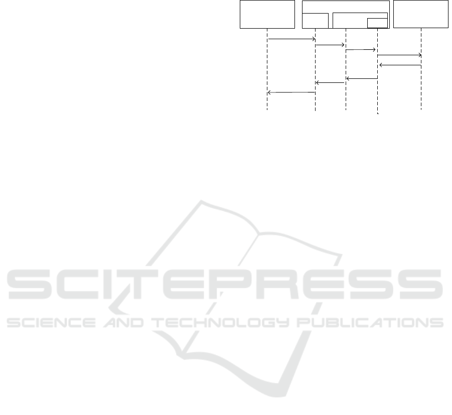
Let us consider an OPC UA Client invoking the
Read service on an OPC UA Node mapping an
oneM2M resource. Figure 3 shows the complete
procedure used in this case, pointing out the relevant
information flow.
OPC UA Client
Registrar CSE
for OPCUA-IPE
OPCUA-IPE
OPC UA
Server
Read Request
HTTP GET Request
HTTP GET Response
Read Response
getDataReq( )
getDataRes()
tr ansl ate Req( )
Interworking
Manager
AE
tr anslateRe s( )
Figure 3: Read Service.
For each Read Request received from an OPC UA
Client, the OPC UA Server will send an internal
request to the Interworking Manager (i.e.
getDataReq() in the figure); this request is aimed to
access the original oneM2M resource relevant to the
OPC UA Node specified by the client in the Read
Request. Read Request will be converted to a HTTP
GET Request, invoked by the AE local to the
Interworking Manager, as shown by Figure 3. The
same figure shows the information flow in the
opposite direction, when the HTTP GET Response is
received. The data content of this service is forwarded
to the OPC UA Server by the Interworking Manager
(through the getDataRes(), as shown in the figure).
The OPC UA Server will update the relevant OPC
UA Node involved in the previous Read Request and
will send the requested attribute values to the OPC
UA Client.
The information flow depicted in Figure 3 for the
Read Service may be used also for the Browse
Service.
Figure 4 shows the procedure applied for each
Write Request sent by an OPC UA Client. POST
method is used in this case to update the value passed
by the OPC UA Client for a specific OPC UA Node,
into the relevant oneM2M resource. The OPC UA
Server will issue an internal request (i.e.
writeDataReq()) to the Interworking Manager, which
will request the AE the transmission of a HTTP POST
Request. On the receipt of the relevant HTTP POST
Response, the Interworking Manager will confirm the
writing operation to the OPC UA Server, by the
writeDataRes(). The OPC UA Client will receive a
Write Response sent by the OCP UA Server
confirming the actual update previously requested.
Let us consider a Subscription already created
inside the OPC UA Server and let us assume that it
contains several MonitoredItems linked to OPC UA
Nodes mapping oneM2M resources. According to the
ICEIS 2020 - 22nd International Conference on Enterprise Information Systems
710
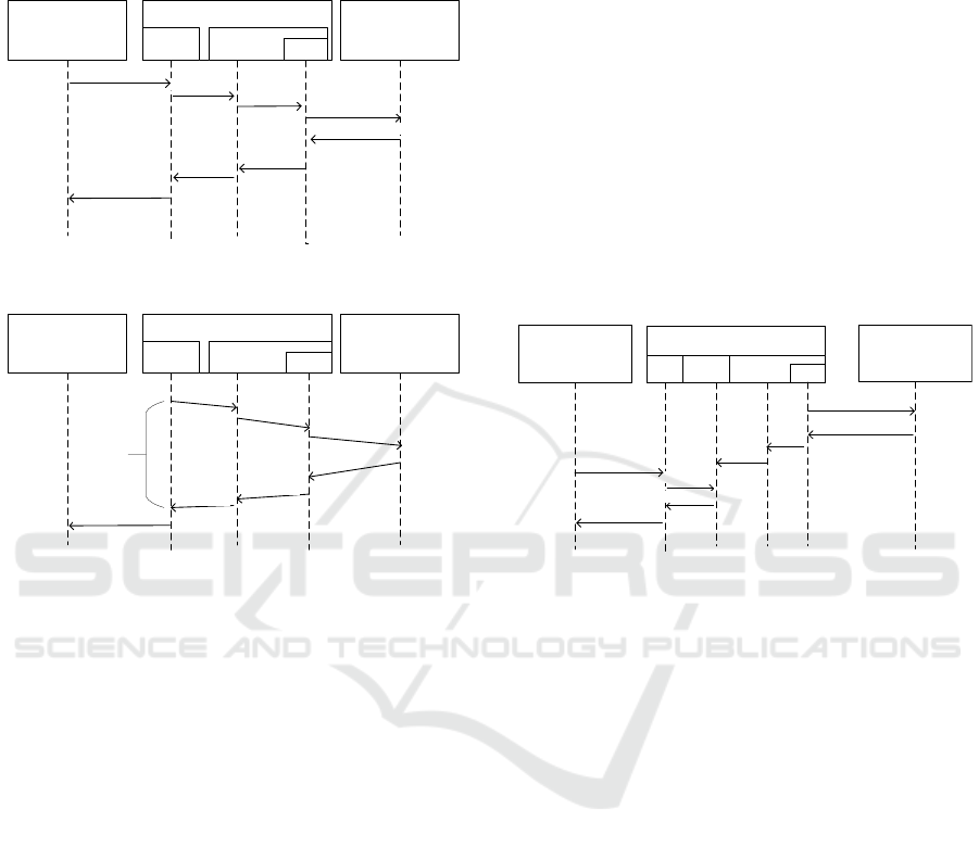
overview on OPC UA, each MonitoredItem has to
sample an attribute of an OPC UA Node each time the
SamplingInterval elapses. Figure 5 shows the
procedure adopted to perform each sampling.
OPC UA Client
Registrar CSE
for OPCUA-IPE
OPCUA-IPE
OPC UA
Server
Write Request
HTTP POST Request
HTTP POST Response
Write Response
writeDataReq()
writeDataRes()
tr ansl ate Req( )
Interworking
Manager
AE
tr anslat eRes( )
Figure 4: Write Service.
OPC UA Client
Registrar CSE
for OPCUA-IPE
OPCUA-IPE
OPC UA
Server
HTTP GET Request
HTTP GET Response
OPC UA Notifications
getDataReq()
getDataRes()
Interworking
Manager
AE
Delay
tr anslat eRe q( )
tr anslat eRe s( )
Figure 5: Subscription/MonitoreItem.
Each time the SamplingInterval elapses, a
getDataReq() is sent by the OPC UA Server to the
Interworking Manager to request the access to the
original oneM2M resource related to the OPC UA
Node linked to the MonitoredItem. As done for the
Read service, a HTTP GET request is used to access
to the oneM2M resource. Once a value is received by
a HTTP GET Response, it is sent to the
MonitoredItem to be enqueued in the relevant queue,
according to the OPC UA specifications. As said in
Section 2, OPC UA Client will receive the values
enqueued by an OPC UA Notification message, as
shown by Figure 5.
5.2 Accessing oneM2M Resources
through Data Cache
This subsection will describe the information flow
inside the OPCUA-IPE for the same services treated
above, but considering the use of the Data Cache as
depicted in Figure 2.
The main assumption made in the paper is that the
Data Cache maintains a consistent view of the
oneM2M resources exposed by the Registrar CSE.
This means that each information must be updated
each time a change in the state of the relevant
oneM2M resource exposed, occurs. In order to realise
this, the oneM2M subscription mechanism described
in Section 2 is adopted. This requires that the AE
inside the Interworking Manager subscribes to the
CSE (by Create <subscription> Request) in order to
receive notification each time a change in the
oneM2M resources occurs. Notifications sent to the
AE are generated depending on the
eventNotificationCriteria set (oneM2M TS-0001,
2019). Interworking Manager inside the OPCUA-IPE
triggers notifications received by the Registrar CSE
and makes the relevant update in the Data Cache. This
is shown by Figure 6, on the right part; as it can be
seen, for each notification received from the Registrar
CSE, the relevant change is updated inside the Data
Cache (by the update() internal service).
OPC UA Client
Registrar CSE
for OPCUA-IPE
OPCUA-IPE
OPC
Server
Data
Cache
Read Request
Create <subscription>
Requ est
notification
Read Res ponse
update()
getDataReq()
getDataRes()
Interworking
Man ag er
AE
notify()
Figure 6: Read Service using Data Cache.
In this scenario, it has been assumed that OPC UA
Server accesses to the Data Cache directly without
intermediaries. Figure 6 shows a Read Request
performed by the OPC UA Client; in this case a
getDataReq() internal service is invoked by OPC UA
Server to access the Data Cache to retrieve the last
updated value relevant to the OPC UA Node specified
in the Read Request.
The information flow depicted in Figure 6 for the
Read Service may be used also for the Browse
Service.
Considering the Write service, each time an OPC
UA Client requests changes to one or more OPC UA
Nodes, it has been assumed that the OPC UA Server
performs only an updating of information maintained
in the Data Cache. In order to guarantee data
consistency with the respect of the original oneM2M
resources, it is required that the update done in the
Data Cache must be reflected to the relevant oneM2M
resources. It has been assumed that Interworking
Manager must be in charge to guarantee that this
occurs.
On account of what said until now, procedure
relevant to the Write Request is quite different from
that seen for the Read service. Figure 7 shows this
Towards Interoperability of oneM2M and OPC UA
711
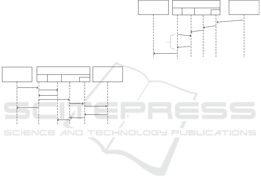
scenario. For each Write Request service, OPC UA
Server sends a writeDataReq() requiring the writing
operation into the Data Cache. It has been assumed
that the content of the writing request is temporally
stored in the Data Cache, and a writeDataRes() is sent
to the OPC UA Server, confirming this temporary
writing operation. It is important to point out that the
actual information maintained inside the Data Cache
is not updated at this moment; this will occur only
when the relevant update will be done inside the
oneM2M Registrar CSE. For this reason, the OPC
UA Server will send to the requesting OPC UA Client
a Write Response, containing a success code that
indicates that the write was not verified. As said in
Section 2, OPC UA specification clearly foresees that
in cases like this the OPC UA Client receives a Write
Response with success code not verified which has
only the aim to confirm the completion of the
previous request but does not give any confirm about
the success of the same request.
OPC UA Client
Registrar CSE
for OPCUA-IPE
Write Request
updateReq()
writeDataRes()
Not Verified
Write Response
writeDataReq()
HTTP POST
Requ est
HTTP POST
Response
update()
OPCUA-IPE
OPC
Server
Data
Cache
Interwor king
Manager
AE
tran sl ate Req()
translateRes()
Figure 7: Write Service using Data Cache.
It has been assumed that the Interworking
Manager must be notified about the changes occurred
inside the Data Cache. This notification may be
realised by the OPC UA Server as shown by the
Figure 7 (i.e. using the internal service updateReq());
it is clear that other solutions may be adopted to reach
this aim. In any case, the Interworking Manager is in
charge to request the transmission of a HTTP POST
Request, sent through its local AE, to request the
actual update of the onM2M resource. Once a HTTP
POST Response is received, the Interworking
Manager can confirm the update previously done in
the Data Cache. In this case, the information
maintained inside the Data Cache is updated with the
temporary information written at the occurrence of
the previous Write Request service, as explained
before. Figure 7 points out the complete information
flow.
About the information flow related to the
sampling operations performed by the Monitored
Items, Figure 8 shows the procedure defined by the
authors. For each MonitoredItem defined inside a
Subscription, access to the data maintained inside the
Data Cache is performed at the interval given by the
SamplingInterval defined for the MonitoredItem.
Figure 8 shows the internal service getData() used to
sample the data maintained inside the Data Cache. As
said for the Read Service, update of these data must
be realised through the oneM2M subscription
mechanism; Figure 8, like Figure 6, shows an
example of notification received from the Registrar
CSE used to update the Data Cache.
OPC UA Client
Registrar CSE
for OPCUA-IPE
OPCUA-IPE
OPC
Server
Data
Cache
notification
Notifications
update()
getData()
enqueue()
Delay
Interworking
Man ager
AE
notify()
Figure 8: Subscription/MonitoredItem using Data Cache.
5.3 Some Considerations Related to the
Performance
In the previous subsections, two set of procedures
aimed to realise interworking between oneM2M and
OPC UA have been presented; one of these is based
on the direct access to the oneM2M resources by the
OPC UA Server whilst the other one is based on the
use of a Data Cache. Both procedures are realised by
the support of the Interworking Manager. The
purpose of this section is to highlight some guidelines
about their use, i.e. when one procedure is to be
preferred to the other and vice versa. In the following,
for the sake of simplicity, the first procedure will be
called “Direct Data Access”, whilst the second one
“Use of Data Cache”.
In OPC UA a fundamental aspect is performance,
from small systems to large business systems. OPC
UA provides a wide set of services whose behaviour
may be customised acting on suitable parameters. The
choice of parameters must meet the requirements of
the system in terms of performance. For this reason,
considerations about the two procedures must take
into account an analysis of the relevant performances,
for each service considered in the previous
subsections (i.e. Read, Write and
Subscription/MonitoredItem).
OPC UA Read Request features a maxAge
parameter (expressed in milliseconds) passed by the
OPC UA Client (OPCFoundation, 2017). As said in
the OPC UA overview, this parameter is used to
direct the OPC UA Server to access the requested
ICEIS 2020 - 22nd International Conference on Enterprise Information Systems
712

value from the underlying data source, if its copy of
the data is older than that which the maxAge
specifies. OPC UA specifications requires that if the
Server does not have a value that is within the
maximum age, it shall attempt to read a new value
from the data source. Also, in the case the maxAge is
set to 0, the Server shall attempt to read a new value
from the data source. In these two cases, the
procedure called “Direct Data Access” may be
preferred to the other one.
If maxAge is set to the max Int32 value or greater,
the Server shall attempt to get a cached value. If the
Server cannot meet the requested maxAge, it returns
its “best effort” value rather than rejecting the request.
This may occur when the time it takes the Server to
process and return the new data value after it has been
accessed is greater than the specified maximum age.
In these two cases, the procedure called “Use of Data
Cache” may be used.
About Write request, no parameters have been
identified that may have a direct influence of the
choice of one of the two procedures. However, it is
important to point out some reasonings about this
service. As shown by Figures 4 and 7, in the two
scenarios “Direct Data Access” and “Use of Data
Cache”, the Server provide a Write Response to the
client, featuring a different meaning. In the “Direct
Data Access” procedure, the OPC UA Client will
receive the confirm that the requested update has been
actually done in the original system (i.e. the
oneMe2M resources). In the other scenario the
confirm is about the temporary update of the local
Data Cache; in this case, the OPC UA Client will not
receive an acknowledgement about the actual update
of the Data Cache. On the other hand, the first
procedure requires longer updating time (i.e. a longer
interval between the Write Request and the Write
Response); the other solution implies a shorter delay.
This consideration may be taken into account when
one procedure or the other one could be used, on the
basis of the kind of confirm requested by the client
and on the basis of the delay in the receiving of the
Write Response.
About MonitoredItem Services Set, choice of
some of the relevant parameters (e.g.
SamplingInterval) plays an important role in the
overall performance and has a great impact on the
choice of one of the two procedures. Setting a low
value for the SamplingInterval means requiring a
minimal latency for the Server to access the data.
Figures 5 and 8 show a parameter called Delay, used
to identify the time interval needed to the Server to
update each Monitored Item in the relevant queue. It
is clear that the duration of this parameter is different
in the two cases. According to the “Direct Data
Access” procedure, the Delay mainly depends on
HTTP Request-Response Round trip time (RTT).
Although the Restful approach doesn’t retain status,
bringing benefits in terms of RTT, the delay may
increase due to problems with the underlying
network. When the other procedure “Use of Data
Cache” is considered, it is conceivable that the Delay
is shorter as the Data Source is “close” to the Server,
not connected to a network.
On the basis of what said until now, some
guidelines about the use of the proposed procedures
may be outlined.
The advantage of “Direct Data Access” is the
simplicity of the representation and implementation.
The OPC Server maintains the actual information
contained in the Registrar CSE, thus avoiding
problems of inconsistency. The need to wait for a
response from the CSE is a disadvantage in terms of
latency, but useful when unconfirmed answers are not
accepted. Many requests from the Client can overload
the network and increase response time. The
MonitoredItem service may suffer from this
configuration if the SamplingInterval is very low.
The other procedure “Use of Data Cache”
overcomes the limits of the first one but introduces
other problems. The OPC UA Server accesses more
quickly the information within the Data Cache,
avoiding network overloading. The services called up
by the OPC UA Client are served with contained
delays. The notification mechanism allows the
OPCUA-IPE to be always updated on state changes
and to reflect them on the Data Source through
updates. These updates need to be handled quickly to
avoid inconsistency issues.
6 CONCLUSIONS
The paper has presented an interworking proposal
between oneM2M and OPC UA. The proposal is
original as no other complete contributions are
present in the current literature with the same subject.
The authors believe that interworking between these
standards is important as they are considered strategic
communication frameworks in Industry 4.0 reference
architecture. Implementation of the OPC UA
AddressSpace exposing oneM2M resources has been
released by the same authors on GitHub (Cavalieri et
al., 2019). This repository contains the XML
representation of the OPC UA Nodes proposed for the
mapping between oneM2M resources and OPC UA
Nodes. This representation can be used to populate
the AddressSpace of OPC UA Server inside the
Towards Interoperability of oneM2M and OPC UA
713

OPCUA-IPE, in order to realise the interworking
from oneM2M towards OCP UA.
ACKNOWLEDGEMENTS
This work was partially supported by the “Piano per
la Ricerca 2016/2018” University of Catania-DIEEI.
REFERENCES
Cavalieri, S., Mulè, S., Salafia, M.G., 2020. Enabling OPC
UA and oneM2M Interworking. IEEE Proceedings
ICIT 2020, 26-28 February 2020, Buenos Aires,
Argentina.
Cavalieri, S., Mulè, S., Salafia, M.G., 2019. oneM2M to
OPC UA Information Models Mapping. Repository
available at https://github.com/OPCUAUniCT/
oneM2M-to-OPCUA-Information-Models-Mapping
European Telecommunications Standards Institute, 2017.
Cross Fertilisation through Alignment, Synchronisa-
tion and Exchanges for IoT. Strategy and coordination
plan for IoT interoperability and standard approaches,
H2020 – CREATE-IoT Project. Retrieved from
https://european-iot-pilots.eu/wp-content/uploads/
2017/10/D06_01_WP06_H2020_CREATE-
IoT_Final.pdf
Industrial Internet Consortium, 2017. The Industrial
Internet of Things Volume G1: Reference Architecture
(Version 1.80), Retrieved from https://www.iiconsor
tium.org/IIC_PUB_G1_V1.80_2017-01-31.pdf
Industrial Internet Consortium, 2018. The Industrial
Internet of Things Volume G5: Connectivity
Framework (Version 1.01), Retrieved from
https://www.iiconsortium.org/pdf/IIC_PUB_G5_V1.0
1_PB_20180228.pdf
Liao, Y., Deschamps, F., Loures, E.F.R., and Ramos,
L.F.P., 2017. Past, present and future of industry 4.0 -
A systematic literature review and research agenda
proposal. International Journal of Production
Research, 55(12), 3609-3629.
Mahnke, W., Leitner, S.H. Damm, M., 2009. OPC Unified
Architecture, Springer-Verlag.
Object Management Group, 2015. DDS Portal – Data
Distribution Service. Retrieved from
https://www.omg.org/spec/DDS/1.4/PDF
Object Management Group, 2019. OPC UA/DDS Gateway.
Retrieved from https://www.omg.org/spec/DDS-
OPCUA/1.0/Beta2/PDF
oneM2M TR-0018, 2018. TR-0018-V-4.0.0: Industrial
Domain Enablement. Retrieved from http://member.
onem2m.org/Application/documentapp/downloadLate
stRevision/default.aspx?docID=29334
oneM2M TS-0001, 2019. TS-0001-V4.3.0:Functional
Architecture. Retrieved from http://member.onem2m.
org/Application/documentapp/downloadLatestRevisio
n/default.aspx?docID=31068
oneM2M TS-0033, 2019. TS-0033-V3.0.0: Interworking
Framework. Retrieved from http://member.onem2m.
org/Application/documentapp/downloadLatestRevisio
n/default.aspx?docID=29581
oneM2M TS-0024, 2019. TS-0024-V3.2.2: OCF
Interworking. Retrieved from http://member.onem2m.
org/Application/documentapp/downloadLatestRevisio
n/default.aspx?docID=29565
OPCFoundation, 2017. OPC UA Part 4: Services, Release
1.04. Retrieved from https://opcfoundation.org/
developer-tools/specifications-unified-
architecture/part-4-services/
W3C, 2004. Web Services Architecture
. Retrieved from
https://www.w3.org/TR/ws-arch/wsa.pdf
Weyer, S., Schmitt, M., Ohmer, M., Gorecky, D., 2015.
Towards industry 4.0-standardization as the crucial
challenge for highly modular, multi-vendor production
systems. IFAC-PapersOnLine, 48(3), 579-584.
Xu, L.D., Xu, E.L., Li, L., 2018. Industry 4.0: State of the
art and future trends. International Journal of
Production Research, 56(8) 2941-2962.
ICEIS 2020 - 22nd International Conference on Enterprise Information Systems
714
