
Software-defined Wireless Sensor Network: WSN Virtualization and
Network Re-orchestration
Indrajit S. Acharyya and Adnan Al-Anbuky
School of Engineering, Computer and Mathematical Sciences,
Auckland University of Technology, Auckland, New Zealand
Keywords: WSN, WSN Softwarization, IoT, WSN Virtualization, WSN Re-orchestration, Software Defined WSN.
Abstract: Flexible reorganization of complex IoT (Internet-of-Things)-based sensor networks is crucial for the
alignment of the sensor network’s operational dynamics with that of the monitored external phenomenon.
Software-Defined Networking (SDN), when supported by Cloud-level Network Virtualization (NV), offers a
prospective avenue for a flexible sensor network that can re-orchestrate as the monitored process demands.
In order to allow for seamless softwarization of the sensor network functional entities, this paper promotes
function modularization and establishment of both virtual repositories of reusable software modules as well
as requisite operational software. An architectural solution that is aligned with Industry 4.0’s ideology is
presented in this work. This along with the software-defined resources is deemed as a viable solution to re-
orchestrate the physical sensor network. By means of example simulation scenarios, this paper highlights the
utility of NV for flexible soft trialling of sensor network topological re-orchestration and highlighting the
possible network downtime associated with that operation. The outcome offers potential for the utilization of
the virtual environment and the dynamics retained within it to offer ground for pre-planning for best possible
re-orchestration scenario that comply with adaptive interaction with the dynamics of the physical
environment.
1 INTRODUCTION
Typical IoT-based sensor network organizations
entail complex architectures in provisioning the
necessary internet connectivity between the physical
wireless sensor network (WSN) and the remote cloud
server (Ezdiani et al., 2017, Ezdiani et al., 2015).
Flexible operation of such IoT-based sensor network
deployments is of critical importance as it engages
with its physical surroundings (Violettas et al., 2017,
Ndiaye et al., 2017). Network Virtualization, in
conjunction with Software-Defined Networking
(SDN), holds considerable potential to unlock the
requisite salience offered by a programmatic and
flexible IoT-based system solution (Modieginyane et
al., 2018, Ojo et al., 2016, Gupta 2018, Acharyya et
al., 2016, He et al., 2019).
The core principle behind SDN is to decouple the
control plane from the data plane to allow for
centralised configurability of the network (via
virtualizing the underlying functions and decision-
making process) (Nguyen et al., 2016, Kobo et al.,
2017, Mostafaei et al., 2018, Bera et al., 2017).
Herein, SDN controller(s) is the essential entity,
which possesses the overall (centralised) view of the
network and is responsible for both management of
the underlying functions as well as efficient routing
of data. On its merger with Network Virtualization,
the role of the SDN is that of an ‘orchestrator’ (e.g.
between ‘sliced virtual networks’) (Modieginyane et
al., 2018). A variety of proposals, employing SDN-
based approaches, have been put forth to address
issues pertaining to flexible and dynamic topological
manipulation of WSNs. (Haque et al., 2019) utilise
the concept of SDN within their proposed ‘SDSense’
architecture to devise a centralised logical controller
that could preside over the configuration of software-
embedded sensors residing in the data plane.
Equipped with topology control modules (amongst
other modules viz., routing and scheduling modules)
as well as provision for user-governed addition and
removal of logical modules, the central controller
plays an important role in influencing the
functionality and topology of the network.
Jemal et al., 2013 pursue self-adaptation within
WSN by means of conventional adaptive approach.
Acharyya, I. and Al-Anbuky, A.
Software-defined Wireless Sensor Network: WSN Virtualization and Network Re-orchestration.
DOI: 10.5220/0009194600790090
In Proceedings of the 9th International Conference on Smart Cities and Green ICT Systems (SMARTGREENS 2020), pages 79-90
ISBN: 978-989-758-418-3
Copyright
c
2020 by SCITEPRESS – Science and Technology Publications, Lda. All rights reserved
79

The paper used certain adaptive middleware control
components. His paper focuses on cluster based WSN
and does not emphasize upon the aspect of network
re-orchestration from a topological standpoint.
Results pertaining to improvement in network
performance as a result of software-defined
topological re-orchestration have not been included
within their paper. The efficacy of establishing a
singular repository catering for data storage as well as
knowledge and functional (core as well as auxiliary)
components in augmenting the flexibility of the
network is not considered. In their approach the
planning is driven via a pre-defined ruleset. Also, the
authors consider a simple case of network rupture
caused by sensor mobility and resolve it by means of
enabling it to ‘adapt’ and connect to the gateway
within range. The aspect of network downtime is not
investigated. With the emergence of technologies like
cloud-based services, software defined networks,
Industrial IoT and virtualization, a more flexible and
open approach could be facilitated for adaptively
manipulating the sensor network. This in effect allow
for open capability of accommodating knowledge
acquisition and learning with time. Here the context
of this paper is to highlight the potential here and
suggest related architecture.
Kipongo et al., 2018 incorporate a ‘Topology
Management’ within the SDN controller, enabling it
with the capability to visualize the topology of their
Software Defined Wireless Sensor Networks
(SDWSN) architecture. No evaluation of the
proposed work is presented. The authors
acknowledge the importance of developing a
topology discovery protocol that would entail
minimum latency, which led them to undertake a
survey of ‘Topology Discovery’ within the SDN
domain. Galluccio et al., 2015 put forth an SDN-
based solution for wireless sensor networks, namely
‘SDN-WISE’ wherein the ‘WISE-visor’ controller,
consisting of a ‘Topology Management’ layer, is
responsible for governance of the logics pertaining to
network management. The role of the ‘Topology
Management’ layer within this architecture is to a)
virtualize underlying network functions, b) extract the
necessary information viz., battery capacity, address,
RSSI (Received Signal Strength Indication), etc. from
the underlying devices and relay them over to the
controller(s) and c) exert control over the stack layers
denoted by the controller(s). Abdolmaleki et al. 2017
incorporate a fuzzy-based topology discover protocol
on top of the SDN-WISE solution to enhance network
efficiency via increasing network lifetime and
decreasing packet losses. In a bid to address device
and ‘network topology’ management issues in IoT-
based WSNs, Bera et al. 2018 employ the concept of
SDN to design a controller equipped with node and
network-specific rule-based management policies to
exert control over the respective packet formats. In
another research effort to enhance software-defined
control over IoT-based sensor network topologies,
Theodorou et al., 2017 put forth the ‘Coral-SDN
architecture’ wherein the centralized ‘CORAL’
controller is entrusted with responsibility to manage
network dataflow. The ‘CORAL controller’
comprises of a modular ‘Decision Making’
subsystem (consisting of certain rules and algorithms)
to allow for rule-based adaptation of network
topology and routing control functionalities. The
controller also consists of a ‘Network Modeller’
module that retains a graph-based abstracted view of
the underlying network. Information pertaining to
radio signal strength and link quality can be derived
from here.
While the above documented state of the art
presents important progress towards the WSN based
cyber-physical operation, it lacks penetration towards
number of operational drivers. These are relevant to
the dynamics of the interaction between the cyber and
physical environments when operational changes
need to be physically implemented. Here, both soft
trialling of various re-orchestration scenarios on a
virtual platform, and examination of performance
implications associated with physical WSN
downtime have, to the best of our knowledge, not
received significant attention. The latter is important
performance measure that reflect capability of the
system to cope with the real time monitoring demand
of the monitored process or phenomenon.
Similar to that embodied by the concept of SDN,
our work also involves virtualization of the
underlying data plane (physical) functions but
emphasizes upon formulation of a ‘Data and
Knowledge’ repository of the necessary WSN core
and auxiliary virtual functional modules that could
reside at the cloud (or the IT-layer) as documented in
a previous research work of ours (Acharyya et al.,
2019). It is anticipated that interactive collaboration
amongst the virtualization unit and the software
repository could offer an adequate framework for
requisite flexible soft trials.
This paper offers novel approach to the support of
the overall process of software-defined re-
orchestration and relate them to the proposed Industry
4.0-based architectural solution. Overall, the
objective of this paper is to present an architectural
solution capable of capitalizing on SDN-enabled
virtualization technology to modularly allow for the
necessary real-time interaction with the operational
SMARTGREENS 2020 - 9th International Conference on Smart Cities and Green ICT Systems
80

dynamics related to those of the prevailing service
needed for the monitored phenomenon.
The rest of the paper is organized in the following
manner. The proposed ideology of the ‘three core
modular network functions that constitute any IoT-
based sensor network is spelt out in section 2. Section
3 details the proposed Industry 4.0-based
architectural framework for IoT-based sensor
network, which allows for the necessary flexible
network re-orchestration through virtualization and
software control. Example sensor network re-
orchestration scenarios, along with certain simulation
based flexible WSN topological re-orchestration
cases, are presented in section 4. The ‘network
downtime’ associated with the re-orchestration
process is highlighted in section 5 by means of two
simulation-based examples. Finally, the conclusion
of this research work is presented in section 6.
2 FLEXIBLE WSN NETWORK
FUNCTIONAL COMPONENTS
An IoT-based sensor network organization should
have basic functionalities for wireless sensing, data
routing and Internet gateway access (Acharyya et. al.,
2019). These three key generic functions can act as
standalone functions on individual devices or
integrate as two or three functions on the same device
depending on the ability of the hardware host to
accommodate for these functions. Modern approach
in offering edge computing allow for further auxiliary
functional units coupled with these three generic
functions in support of the system computational
requirements and enhance the real time performance.
Figure 1 depicts the ‘core’ and example ‘auxiliary’
roles executed by each of the three generic functions.
As shown in figure 1, core activities associated
with ‘Leaf function’ pertain to ‘Sensing and Data-
acquisition’ functions viz., sensor selection amongst
heterogeneous sensing, and sampling rate relevant
data acquisition of each type of the required sensing
as well as maintenance of connectivity with router (or
Gateway) node via bidirectional radio messages. On
the other hand, example auxiliary activities that may
be assumed by the leaf node include edge-computing-
based data management tasks such as buffering,
queueing, compression, and digital signal processing.
Also, depending upon capabilities possessed by the
hardware employed, it may assume and execute
higher functional roles of ‘data routing’ and IoT-
enabled connectivity utilizing protocol such as
6LowPAN. This, in effect, enables the node to be
directly accessible through the internet. Core and
auxiliary functions pertaining to ‘Router node’ are
also depicted in figure 1. Herein, routing of sensed
data (obtained from the leaf nodes) over to the ‘sink’
or ‘Gateway nodes as well as acting as a ‘cluster-
head’ for a group of lower level (leaf) sensor nodes
are identified as two key core functions that could be
attributed to a router node. Its auxiliary functions may
include aggregation and processing of group of data,
undertaking the role of leaf node or that of an IoT-
enabled Gateway node, depending upon resources
encompassed by the hardware. Finally, as depicted in
figure 1, the core activities associated with the
gateway node include facilitating as a local sink for
the data generated by the network, escalating the
accumulated data to the upper level IT-layer over the
internet. The ‘Edge Computing’-based tasks viz.,
management and processing of sensed data, buffering
and/or organizing queue of sensed data, in addition to
assuming the role of a leaf node, if both necessary and
feasible, constitute its auxiliary activities.
Figure 1: Example core and auxiliary activities that can be
attributed to main functions composing an IoT-enabled
sensor network organization viz., (a) Leaf (or end device)
sensing functionality, (b) Routing functionality and (c) IoT-
based WSN Gateway functionality.
The above categorization of IoT-based sensor
network functionalities allows for scalability of the
network. For example, a single node system has all
the functions integrated in one node. The gateway
here also assumes the sensing capabilities, which is a
typical IoT device. A two-node network has both the
leaf and gateway functionalities. Further sizes should
include two or three type of core functions involved.
Typical example organizations of star, tree or multi-
Software-defined Wireless Sensor Network: WSN Virtualization and Network Re-orchestration
81
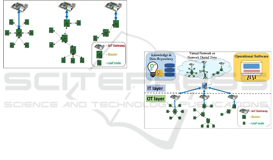
hop connectivity are shown by figure 2. They are
quite common in sensor network organizations.
Example implementation is the use of TI CC2538 as
wireless sensor and/or wireless router is quite
common as the device offers numerous capabilities of
facilitating interaction with heterogeneous sensing,
facilitating reasonable computational and storage
capability and hosting wireless low-power protocol.
The latter includes the IoT capability through the
6LowPAN. The Raspberry Pi is another typical
example for a gateway implementation. This offers
ample resources for facilitating the bridging between
the low power wireless sensor network protocol and
the internet protocol and facilitate the needs for the
transport layer.
Figure 2: Example WSN implementation scenarios core (a)
Star Connectivity, (b) Tree Connectivity and (c) Serial
Connectivity.
Cloud-based virtualization support can be gained
using operating system (OS) like Contiki. This OS
offers Cooja simulation environment. Cooja is a
Contiki-based simulator wherein the same Contiki-
OS based C codes are used for compiling and
programming the virtual Cooja nodes as that
employed for the TI CC2538 wireless sensor-cum-
transceivers. By virtue of this, the virtual Cooja
simulator mimics the physical processes of the
underlying TI CC2538-based physical sensor node or
network. Such relation between the physical network
entities and their virtual counterparts, enable services
such as remote re-orchestration and associated
performance analysis.
Defining these controls as software modules
would render them capable of undergoing dynamic
configurational manipulations. This is by switching
over from one functional role to another and/or
incorporating additional ‘IoT-WSN’-centric software
tasks, there by allowing for augmented flexibility of
the individual functions, and hence overall WSN
network. As a step to achieve this, it is deemed viable
to establish a structured ‘Data and Knowledge
Repository, which besides accommodating for
historical data as well as solution patterns, also caters
for the formulation of both ‘core’ and ‘auxiliary’
software modules that could be accessed by the SDN-
enabled virtualization environment. This aspect is
discussed later in section 3.
3 PROPOSED ARCHITECTURE
The proposed architecture for IoT-based sensor
networks is as depicted in figure 3. At the upper level
there are two major layers. These are the ‘Information
Technology’ (IT) and the ‘Operational Technology’
(OT) layers that accommodate for the virtual and
physical layers respectively. The IT-layer hosts the
‘Data and Knowledge’ repository as well as control
and virtualization management resources. This
facilitate the components for establishing and
managing the virtualized environment. It should also
allow for performing the testing of new virtual
network setting before the necessary network re-
orchestrations applied on the physical network at the
OT layer.
Figure 3: Proposed IoT-based sensor network organization.
The objective is for orchestration and testing of
the virtual network behaviour before final reflection
on the physical network. Being scalable in nature, the
‘Data and Knowledge’ repository could also
accommodate for reusable patterns that relate to
previous experiences, besides hosting the known
knowledge components. Accommodation for known
solutions associated with known events is one of the
important features. This allow the system to retain
and accumulate experiences with time. The platform
also facilitates important playground for assessing
any planned changes to the physical environment
before actual execution of the change. This may
impose real time sensitive demands especially when
it comes to applications with high degree of
dynamics.
The OT layer consists of the physical wireless
sensor network nodes deployed for the necessary
SMARTGREENS 2020 - 9th International Conference on Smart Cities and Green ICT Systems
82

sensing and monitoring purposes. Physical data
collected by the various clusters of ‘leaf nodes’ or
‘end devices’ are routed by their respective ‘router’
nodes which pass it over to their respective IoT-
enabled gateway nodes. Certain sensor-motes as the
TI CC2538 employed by us (and as previously
alluded to in section 2) could be software-
reconfigured to execute multi-functional tasks. For
example, upon incorporation and activation of the
respective software component, they could execute
dual functionalities of both router and leaf node, as
required. When functioning as a leaf node, the TI
CC2538 can acquire heterogeneous sensor data viz.,
temperature of external surroundings, radio signal
strength, etc. Node-operational parameters pertaining
to physical layer (e.g. sensor selection, rate of
sampling of the heterogeneous data, etc.), MAC layer
(e.g. implementation of communication protocol viz.,
TDMA, CSMA, etc.) can be dictated through
software control.
The ability to flexibly switch to a different
functional role when required is an important feature
to realize the vision of a software defined and flexible
IoT sensor network organization that can be
orchestrated through software control. As mentioned
earlier, any IoT-based software-defined sensor
network organization is composed of three key
functional modules viz., Leaf function, Router
function and the IoT Gateway function, that could be
either switched, merged, disassembled or tweaked by
means of software control. Advancements made in
field of SoC technology render certain wireless-
microcontroller sensor-transceiver devices to be
capable of accommodating for and executing more
than one of the core functionalities at a time. Such
hardware sensor-cum- could be pre-configured or
loaded with one or of the three functions with the help
of the related software.
Equipped with protocol conversion capabilities as
well as computational, IoT-enabled gateway such as
the Raspberry Pi facilitates the necessary bridging of
protocols. It could cater for ‘Edge Computing’ i.e. the
requisite data processing and computation operations
(viz., data compression, data buffering, queueing [1,
2], etc.) prior to escalating the sensed data (obtained
from the router nodes) to the IT-layer over the
internet. The IT layer could either be accessed by a
single gateway that relates to all other cluster heads
or by multiple gateways (governing their respective
clusters) simultaneously. The ability of nodes
switching functions through software allows for
numerous topological scenarios and hence offer
flexibility for the network to maneuver with the
situation.
The IT layer is composed of three main
components viz., ‘Data and Knowledge Repository’,
‘Operational Software’ as well as the ‘Virtual
Nework’.
The ‘Data and Knowledge Repository’ is
responsible for storage and management of historical
sensed data retrieved from the OT layer and in
particular those related to important events that are
associated with the virtualization of important
processes. Its inherent knowledge components
contribute towards formulation of core and auxiliary
network functions that are meant to be accessed by
the virtualization unit. Herein, historical data is
deemed valuable for testing new virtual organization
on the various possible process behaviour before real-
life implementation on the physical network (OT
layer). Finally, retaining historical solution patterns
as system past experiences is another important role
associated with the ‘Data and Knowledge Repository’
unit.
The ‘Operational Software’ related to the key
operating tools for the development of codes relevant
to the network functions. It also facilitates the
development of possible training of software
components or network organization for handling a
given event. Contiki for example is important part of
this block in generating the wireless node executable
code and managing the Cooja simulator. Data
processing and analytics software tool could also
have important role here that supports the function of
the network virtualization. Dynamic monitoring of
the change in RSSI over time may for example, reveal
that a given node within the network is heading
towards dis-connectivity of the current associated
data path. This, in turn may indicate the need for re-
orchestrating the network’s topology in order to avoid
any subsequent issues. Similar example to analytical
software like Matlab could offer the wide range of
processing and soft computing capabilities.
The virtualization unit reflects the behaviour of
the underlying physical network. It represents the
mirror image of the physical network from both the
topological organization as well as functional
operational software for each node within the
network. The history data represent the network
performance and the extent to which it maintains the
required flow of data through the network and into the
sink. Another important and challenging aspect of
virtualization is that of the representation of the
physical environment where the physical network is
located. This has an important impact on the received
radio signal strength and is very difficult to be
mimicked precisely. The availability of machine
intelligence and learning within the cloud will play an
Software-defined Wireless Sensor Network: WSN Virtualization and Network Re-orchestration
83

important role here. One may initially approximate
through modelling or characterization of the physical
behaviour and then teach the system with more
accurate behaviour with time.
The following section offers example processes
within WSN that are virtualized in the context of
network topology and embedded software. The three
network functions are represented within the software
with an ability to get dynamically replaced as per the
outcome of the re-orchestration process.
4 EXAMPLE NETWORK RE-
ORCHESTRATION
SCENARIOS
4.1 Simple Network Manipulation
Consider the following example wherein two
different Contiki-generated, virtual ‘software
functional modules’ are interchangeably
implemented onto the same virtual network element
to realize different WSN functionalities and thus,
completely alter the network behaviour. This example
has been performed within the virtual resource of the
Cooja simulator available within Contiki. Herein, the
‘broadcast_open’ function presented within the
Contiki-based software ‘C’ code was altered in a
minor way to realize both the necessary functional
modules, and thus, influence the communication
protocol.
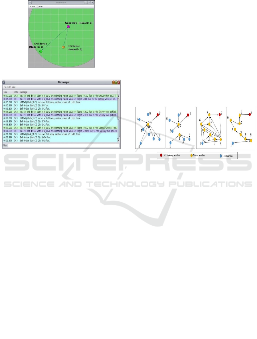
As shown in figure 4a, virtual Cooja node, Node
ID: 1 has been configured to behave as an end device
by programming as ‘end device’ (core) virtual
software functional module. Similarly, Node ID: 2
and Node ID: 3 acts as ‘router’ and ‘gateway’ devices
since they have been configured with ‘router’ and
‘gateway’ functional software modules respectively.
It is important to note that since the intermediate
Node ID: 2 is configured to behave as a router, the
network behaves as a ‘multi-hop network’. Such
multi-hop network connectivity facilitates dataflow
from the end-device (Node ID: 1) to the gateway
(Node ID: 3) via the router (Node ID: 2). Thus, the
sensed dataflow in this case, emanates from the ‘end-
device’ function to the ‘router’ function, and finally
to the ‘gateway’ function. The mote output window
screenshot obtained from Cooja wherein random light
data generated by the end device reaches the gateway
via the router node is as shown in figure 4b.
4(a)
4(b)
Figure 4: (a) Virtual representation of a simple multi-hop
network; (b) Mote output window screenshot depicting
multi-hop network behaviour.
Upon implementation of a separate virtual
software ‘functional module’ i.e. the ‘leaf node’
‘functional module’ on the same virtual Cooja node
(Node ID: 2), it ceases to be a router and acts an end
device. Without the router node, the same virtual
network now behaves as a ‘star network’ as can be
seen from figures 5a and 5b. A separate virtual
‘functional module’ is employed for the gateway in
order to re-orient the network to follow a TDMA-
based scheme, as opposed to the CSMA-based
protocol implemented earlier.
This star network connectivity facilitates polling-
based data flow i.e. from the end devices (Node_ID:
1 and Node: ID 2) to the gateway (Node ID: 3) is as
shown in figure 5a. Thus, for providing star network
service, the direction of the sensed dataflow in this
case involves constant sequential switching between
‘end-device 1 virtual functional module’ to ‘gateway’
virtual functional module and ‘end-device 2 virtual
functional module’ to ‘gateway’ virtual functional
module. The ‘mote output’ window screenshot
illustrating the polling-based data flow within the
star-topology based network is shown in figure 5b.
Thus, the above example aptly demonstrates that the
network can be orchestrated to switch from case I to
case II and vice-versa via implementation of the two
different functional modules. This could be useful
action to support (for example) reconnecting a mobile
SMARTGREENS 2020 - 9th International Conference on Smart Cities and Green ICT Systems
84
node to the network when it becomes out of the line
of sight with the Gateway.
5(a)
5(b)
Figure 5: (a) Star implementation of the multi-hop network
(shown in Fig. 4); (b) Mote output window screenshot
depicting multi-hop network behaviour.
Herein, the role of software-defined re-
orchestration in reformulating the functional
behaviour of node 2 (originally a router function) to
that of a ‘leaf function’ is depicted. This example,
albeit simplistic, attempts to convey that such
incremental re-orchestrations taking place at the
individual node level are instrumental in altering the
topological orientation and thereby the flow of data
within the network. This also demonstrate the
software defined approach in isolating the data from
the control. Here, while the network offers the data
path, the functions of the node are change through the
software to alter the path. Multiple similar
incremental actions may take place for a more
complex network in re-orchestrating the topology of
the overall network. The following section supported
by figure 6 offers illustrations here.
Owing to the numerous flexible parameters
available for software-reconfiguration within the
different layers of the Contiki-stack, our IoT-WSN
can possess a broad range of software functional
modules that can be exploited to extract more
complex network behaviour in catering for a wide
range of service requirements.
4.2 Scenarios for Network
Re-orchestration
Different sensing-based applications necessitate
dynamic changes in software-defined node-function.
This creates an avenue for re-orchestrating the current
network topology. Irrespective of such topological
variations, the three functions of ‘leaf node’, ‘router
node’ and ‘IoT gateway node’ are indispensable with
respect to execution of the mandatory tasks of
‘sensing and data’ acquisition, data routing and data
transportation to the Cloud respectively. Figure 6
illustrates example topological variations of a
stationary IoT-based sensor network that may be
subjected to software-defined re-orchestration.
(a) (b) (c) (d)
Figure 6: Certain possible topological formations that an
IoT-based sensor network can adapt to owing to software-
defined re-orchestration: (a) Star Topology; (b) Tree
Topology, (c) Mesh Topology and (d) Multi-hop Topology
respectively.
For example, software-defined reformulation of
Node 4 from leaf node to a router node could enable
the network to re-orchestrate its topological
orientation from a ‘star’-based network depicted in
figure 6a to a tree-based network shown in figure 6b.
Through similar software-defined re-orchestration,
mesh and multi-hop-based topological frameworks
could be realised, as shown in figures 6c and 6d
respectively.
To gauge the change in network performance
derived through software-defined topological re-
orchestration, consider the following experimental
case. Initially, the 8-node network is assumed to
operate under a multi-hop topological framework, as
depicted in figure 6d. Figure 6a, on the other hand,
depicts the same network re-orchestrated to operate
within a star topological framework.
The sampling rate of data being sensed by the end
devices is incremented (in steps of five samples per
second from one sample per second to 20 samples per
Software-defined Wireless Sensor Network: WSN Virtualization and Network Re-orchestration
85

second) for both network topologies to observe the
implications, as depicted in Table 1. The ‘packets
lost’ parameter is used in this experiment for the
performance evaluation purposes.
Table 1: The impact of increasing sampling rates on the
packet loss incurred by a network of 8 nodes for different
scenarios.
Sampling rate
PPS (i.e.
‘Packets per
second’)
Packets lost
PPS
Multi-hop
Packets lost
PPS
Star-CSMA
Packets
lost PPS
Star-
TDMA
1 0 0 0
5 3 0 0
10 5 0 0
15 8 4 0
20 10 0 0
Upon re-orchestrating the same network to a star
topological framework, it was observed that no
packet losses are incurred when the network is
operated on TDMA protocol (wherein each node
transmits its data during its own particular/distinct
time slot). When increasing the sampling rate to 20
PPS, the multiple-hop topology reflects gradual
increase in packet loss. The star network under the
CSMA protocol started losing 4 PPS at the 20 PPS
rate. Meanwhile, the star network under the TDMA
protocol persist on passing all the packets without
loss.
Thus, it could be inferred that whilst operating in
service conditions demanding higher sampling rates,
star-based topological frameworks fare better than
multi-hop networks in terms of mitigating the overall
packet losses incurred by the system. Also, by
introducing the functional changes using software
defined network function approach, ‘multi-hop’-
based topological networks could resort to star-based
topological framework via software-defined re-
orchestration to restrict the number of packets lost.
This example signifies the importance of
embedding network behavioural knowledge within
the virtual network in catering for foreseeing
performance analyses prior to actual re-orchestration
execution at the OT layer.
5 NETWORK DOWNTIME
DURING
RE-ORCHESTRATION
Implementation of the outcome onto the real-life
physical network may temporarily entail partial or
complete service disruption. However, it is viable to
ascertain this through experimentation. The entire
duration of the network service disruption i.e. from
the first instance of breakdown of service up until the
complete resumption of the normal dataflow and
service post-reorchestration, is referred to as ‘network
downtime’. It is necessary to investigate this issue
through an example scenario so as to determine the
extent upon which a given software-defined
reorchestration processes affect network ‘uptime’.
We deem it viable to split the re-orchestration
process across three phases viz., ‘Data analysis and
event identification phase’, ‘Re-Orchestration
Planning phase’ and lastly ‘Re-Orchestration
Execution phase’. These are briefly touched upon in
the following paragraph but are discussed in detail in
the subsequent parts of the paper.
Dynamic monitoring of network data at the cloud-
level with the help of virtualization may help in
revealing any important event that could potentially
disrupt network operation (either partially or in
complete). For example, events such as a mobile
router node moves away from the connectivity chain
or reaching low battery energy level may indicate that
it needs to be replaced with another router node in
order to sustain the flow of data for the dependent
chain of nodes. Such events are continuously
monitored during the on-going ‘Data Analysis and
Event Identification’ phase by means of a knowledge
component present within the ‘Data and Knowledge
Repository’ hosted by the cloud. Upon detection or
identification of any such event necessitating network
re-orchestration, an alarm is triggered within this
phase to initiate the next phase i.e. ‘Re-orchestration
Planning Phase’.
The ‘Re-orchestration Planning Phase’ firstly
involves proactive accumulation of the essential
pieces of information from the OT layer (that also
influences virtual network) as required for triggering
of the re-orchestration process. Based on analysis of
these collected data, replacement router selection
process takes place. Successful identification of
replacement router set the stage for the physical re-
orchestration of the physical network at the OT layer.
Progression of any re-orchestration process in this
sequence ensures confinement of any downtime
experienced by the network to the last i.e. ‘Re-
orchestration Execution Phase’ alone.
With respect to the considerations stated above,
consider the following example of a cloud-monitored
network that is required to undergo re-orchestration.
Herein, a physical network that requires election of a
suitable cluster-head for a group of leaf nodes owing
to a special condition causing the existing cluster-
head or router to start moving out of reach of the
SMARTGREENS 2020 - 9th International Conference on Smart Cities and Green ICT Systems
86

gateway. The virtual network for this scenario is
depicted in figure 8 wherein, a mobile router node (i.e.
node 5) which is due to depart, acts as a cluster-head
for four mobile end devices i.e. nodes 1, 2, 3 and 4
and relays the sensed data so accumulated to a
Gateway represented by node 6. The four connected
devices are acting as leaf nodes. Some of these leaf
nodes can assume router function. For the sake of
simplicity, it is assumed that leaf nodes can only
communicate with the gateway though a router even
if they are within the communication range of each
other. However, a virtualization environment, being
unbounded by the physical communicational
limitations of the real world in consideration could
provision for such direct communication between the
leaf nodes and the gateway (and vice versa), if
required.
Figure 8: Simulation of network consisting of a (departing)
mobile router and four end devices within Cooja.
As ‘part of the on-going monitoring activity
(during the ‘Data Analysis and Event Identification’
phase) within the Cloud knowledge repository, a
given knowledge component continuously monitors
the radio signal strength (RSSI) between the router
node 5 and the gateway node 6. By means of watching
the history data of corresponding RSSI values
between the router and the gateway. As it recognizes
the pattern of the router departure, it raises a trigger
to kick start the ’Re-orchestration Planning phase’
phase.
In the ‘Re-orchestration Planning phase’, another
known knowledge component works on the
identification of the potential nodes that could replace
the current router. In this example, we have assumed
that the three nodes (1, 2 & 3) can assume router
function. Meanwhile, node 4 can only be a leaf
function and hence will be eliminated from the
competition for the router role (see figure 9). The
appropriate selection of the replacement router
among nodes 1, 2 and 4 follow the execution of a
given fitness model. The model requires the
measurement of three parameters. These are strength
of the elected node to reach all the relevant leaf nodes
using the RSSI reading, strength of the elected node
to connect to the gateway using the RSSI readings and
the elected node backup battery energy level.
Equal weightage has been assumed for each of
these three parameters for this example. This,
however, could change on a case-by-case basis or
through long term learning process. As alluded to
earlier, a software knowledge component takes the
responsibility of computing and comparing the
‘normalized’ weight values for each of the participant
end devices and identify the replacement router. The
mathematical expression pertaining to the fitness
model i.e. normalized weight i.e. ‘W
N
’ (for each
participant end device) is as follows:
W
N
= [m
i
×RSSI
AVG_EDs
] + [m
i+1
×RSSI
ED-G
] +
[m
i+2
×B
ED
],
where,
m
i
, m
i+1
, m
i+2
represent the weights associated with
each of these three factors,
‘RSSI
AVG
_
EDs
’ represent the average radio signal
strength of a participant end device with respect to all
the other relevant end devices within the cluster,
‘RSSI
ED-G
’ represent the radio signal strength of a
participant end device with respect to the Gateway
and
‘B
ED
’ pertains to existing battery level of a participant
end device.
The participant end device with superior fitness
value will be elected as the replacement router. This
in turn facilitates the decision for actual physical re-
orchestration. The ‘execution’ phase involves several
sequential transactions of message exchange amongst
the nodes to attain their ‘re-orchestrated’ status within
the final state of the network.
Figure 9 below provides an abstracted
representation of the requisite communication
messages exchanged amongst the constituent nodes
across the three phases, for the execution of the
necessary election process.
Herein, during the on-going ‘Data Analysis and
Event Identification’ phase, the Gateway node 6
regularly transmits message ‘M
G-R
’ to the router node
5 to determine its RSSI value with respect to it (at a
set transmission rate). The router node, in turn,
responds with the message ‘M
R-G
’ to the Gateway
node, along with its battery level value. This data is
sent to the cloud for storing the trend. It will also be
monitored at the cloud by the relevant knowledge
component associated with the ‘Re-orchestration
Planning’ phase.
Software-defined Wireless Sensor Network: WSN Virtualization and Network Re-orchestration
87
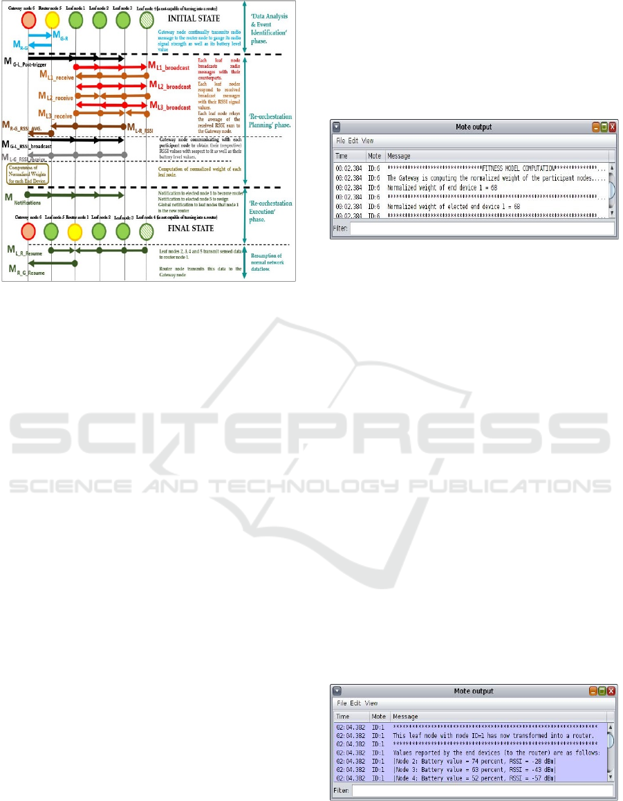
Figure 9: Abstracted representation of the exchange of
communication messages across the three different phases
to elect a suitable clusterhead from the constituent end
devices to replace the departing clusterhead.
During the ‘Re-orchestration Planning’ phase, the
gateway node (being capable of directly
communicating with the all the leaf nodes,)
broadcasts message ‘M
G-L
_
Post-trigger
’ to the leaf nodes
capable of turning into routers (nodes 1, 2 and 4 in
this case) directing them to transform to the role of a
router. These ‘leaf-turned router’ nodes i.e. node 1, 2
and 3 then broadcast radio messages ‘M
L1
_
Broadcast
’,
‘M
L2
_
Broadcast
’ and ‘M
L3
_
Broadcast
’ respectively to the
other leaf nodes (i.e. all the three participant leaf
nodes as well as the lone, non-participant, router-
incapable leaf node 4) to obtain their RSSI values
with respect to each other. Upon reception of these
broadcast messages, the other listening leaf nodes
respond with their respective RSSI signal values,
denoted by messages ‘M
L1
_
receive
’, ‘M
L2
_
receive
’ and
‘M
L3
_
receive
’. Through message ‘M
L
_
R
_
RSSI
’, each
participant leaf node relays the average of the
received RSSI signal values over to the router node,
which in turn relays the combined information over
to the Gateway node as denoted by message
‘M
R
_
G
_
RSSI_AVG
’. The Gateway node then transmits
radio messages ‘M
G
_
L
_
RSSI
_
broadcast
’ to leaf nodes 1, 2
and 3, in order to determine their radio signal strength
with itself as well as acquire their battery level values.
The leaf nodes respond with message
‘M
L
_
G
_
RSSI
_
receive
’ to the gateway node.
Upon reception of the requisite parameters from
all the participant nodes, the Cloud based dedicated
knowledge component executes the ‘planning’
process wherein the normalized weight values for
each of the constituent participant end devices are
computed and compared. The participant end device
with the most superior normalized weight will be
notified of its new role as a cluster head for the
remaining end devices. Figure 11 depicts the mote
output screenshot pertaining to the election outcome
processed at the IT-layer.
Figure 10: Screenshot of the mote output window within
Cooja depicting messages pertaining to the election
outcome.
This is followed by the final stage of the re-
orchestration process i.e. the ‘Re-orchestration
Execution phase’. This proceed with implementing
the above outcomes derived through the ‘planning
process’ onto the actual physical or ‘OT’ layer
components. Herein, a number of requisite sequential
messages, represented by ‘MNotifications’ get executed
involving the Gateway notifying the elected node of
its new role as a ‘router node’, then notifying the
departing router to resign its ‘router’ role and switch
over to the role a ‘leaf’ node, then notifying all the
leaf nodes about the new router i.e. node 1 and finally
the resumption of the dataflow within the network i.e.
gathering of all the end devices’ sensed data by the
newly elected router (denoted by message
‘M
L
_
R
_
Resume
’, upon traversal up to the approximate
position of the previously existing router within the
range of the gateway) and relaying it over to the
Gateway node, denoted by message ‘M
R
_
G
_
Resume
’.
Figure 11 depicts the instant at which the
successful candidate (i.e. leaf node with node ID 1)
switches over to the role of a router and commences
the act of accumulating data from its leaf nodes.
Figure 11: Screenshot of the mote output window within
Cooja depicting messages pertaining to the election
outcome.
SMARTGREENS 2020 - 9th International Conference on Smart Cities and Green ICT Systems
88

As alluded to earlier, the ‘end-to-end’ downtime
is calculated from the instant of time at which normal
service delivery is interrupted up to the instant of time
at which its normal network dataflow is restored. In
our work, the network downtime incurred takes place
from the instant router node 5 has been notified to
become a leaf node until resumption of data flow of
all leaf nodes through node 1 (as a replacement
clusterhead). The instant of time wherein the normal
dataflow service within the network is completely
restored. Upon figuring out the number of messages
getting executed within this phase from the above
account, it is found that the network experiences a
downtime of the order of ‘six’ communication
messages for this particular case of network re-
orchestration. Results such as above are only relative.
Since the bulk of the re-orchestration process takes
place within the virtual environment and that the
motive of this exercise was to merely gauge the
relative downtime incurred as a result of the network
re-orchestration process, the Contiki simulator has
been relied upon and employed entirely to draw
tentative evaluation results. It is duly realized actual
downtime incurred can only be determined through
physical experimentation and forms part of the future
work. At this stage, virtualization is based on real life
data. Further reflection to more involved test will be
consider in future work. Also, in order to obtain a
more accurate network downtime value, practicalities
associated with real-world communication process
viz., the exact protocol being employed, persisting
conditions of communication, etc. need to be factored
in.
This example reflects the viability of the
virtualization platform (operating in conjunction with
the knowledge software components within the IT-
layer) in working out a suitable re-orchestration’s
scenario during the first two phases before decision
for re-orchestration execution phase takes place.
However, although the bulk of the computation could
take place at the cloud, the knowledge software
components (responsible for the desired
computations) could also reside at the ‘edge devices’
viz., Gateway, router nodes, etc. Herein, it is
worthwhile to state that this research work solely
focusses on the extent of downtime incurred as result
of the network re-orchestration process whereas the
future work will revolve around analysis of impact of
the network parameters such as sampling rate,
protocol employed, number of nodes, number of
hops, topology, etc. on the re-orchestration latency.
However, the aspect of data loss too (as a result of the
network re-orchestration process) is an interesting
research proposition that could be pursues as part of
the future work.
6 CONCLUSIONS
This research work attempts at addressing the aspect
of software-defined functional and topological re-
orchestration of sensor networks through
modularization and virtualization of the WSN
functions within an architectural organisation based
on the Industry 4.0-based ideology. Downtime
suffered by the network as a result of the re-
orchestration largely depends on the structural
arrangement i.e. topological orientation, density of
nodes, number of hops, number of messages to be
exchanged amongst the various constituent nodes (as
per the re-orchestration strategy obtained from the
‘Re-orchestration Planning’ phase), etc. While
majority of WSN systems have the ability for
absorbing this down-time without any significant
impact, high dynamic applications involving mobile
sensor nodes could be quite critical towards such
down-time. Further work will involve determination
of the actual downtime incurred during the ‘Re-
orchestration phase’ using the real-life hardware
nodes. Furthermore, analysis of impact of the network
parameters such as sampling rate, protocol employed,
number of nodes, number of hops, topology, etc. on
the re-orchestration latency will also be pursued.
The paper has emphasized upon the significant
role of WSN virtualization and software repository of
knowledge components in offering the necessary
environment for monitoring, and if necessary, re-
orchestrating the dynamics of the physical network.
This introduction should stimulate the research in this
novel and important area of WSN.
REFERENCES
Ezdiani, S., Acharyya, I. S., Sivakumar, S., & Al-Anbuky,
A. (2017). Wireless Sensor Network Softwarization:
Towards WSN Adaptive QoS. IEEE Internet of Things
Journal, 4(5), 1517–1527. doi:
10.1109/jiot.2017.2740423
Ezdiani, S., Acharyya, I. S., Sivakumar, S., & Al-Anbuky,
A. (2015). An IoT Environment for WSN Adaptive
QoS. 2015 IEEE International Conference on Data
Science and Data Intensive Systems. 586-593 doi:
10.1109/dsdis.2015.28
Violettas, G., Theodorou, T., Petridou, S., Tsioukas, A., &
Mamatas, L. (2017). Demo abstract: An
experimentation facility enabling flexible network
control for the Internet of Things. 2017 IEEE
Conference on Computer Communications Workshops
(INFOCOM WKSHPS). 992-993 doi:
10.1109/infcomw.2017.8116526
Software-defined Wireless Sensor Network: WSN Virtualization and Network Re-orchestration
89

Ndiaye, M., Hancke, G., & Abu-Mahfouz, A. (2017).
Software Defined Networking for Improved Wireless
Sensor Network Management: A
Survey. Sensors, 17(5), 1031. doi: 10.3390/s17051031
Modieginyane, K. M., Malekian, R., & Letswamotse, B. B.
(2018). Flexible network management and application
service adaptability in software defined wireless sensor
networks. Journal of Ambient Intelligence and
Humanized Computing, 10(4), 1621–1630. doi:
10.1007/s12652-018-0766-7
Ojo, M., Adami, D., & Giordano, S. (2016). A SDN-IoT
Architecture with NFV Implementation. 2016 IEEE
Globecom Workshops (GC Wkshps), 1-6. doi:
10.1109/GLOCOMW.2016.7848825
Gupta, G. P. Software-Defined Networking Paradigm in
Wireless Sensor Networks. Advances in Systems
Analysis, Software Engineering, and High-
Performance Computing Innovations in Software-
Defined Networking and Network Functions
Virtualization, 254–267. doi: 10.4018/978-1-5225-
3640-6.ch012
Acharyya, I. S., & Al-Anbuky, A. (2016). Towards wireless
sensor network softwarization. 2016 IEEE NetSoft
Conference and Workshops (NetSoft). 378-383.
doi: 10.1109/NETSOFT.2016.7502470
He, M., Alba, A. M., Basta, A., Blenk, A., & Kellerer, W.
(2019). Flexibility in Softwarized Networks:
Classifications and Research Challenges. IEEE
Communications Surveys & Tutorials, 21(3), 2600–
2636. doi: 10.1109/comst.2019.2892806
Nguyen, T. M. C., Hoang, D. B., & Chaczko, Z. (2016).
Can SDN Technology Be Transported to Software-
Defined WSN/IoT? 2016 IEEE International
Conference on Internet of Things (IThings) and IEEE
Green Computing and Communications (GreenCom)
and IEEE Cyber, Physical and Social Computing
(CPSCom) and IEEE Smart Data (SmartData)Chengdu.
16-19 December; 234-239. doi: 10.1109/iThings-
GreenCom-CPSCom-SmartData.2016.63
Kobo, H. I., Abu-Mahfouz, A. M., & Hancke, G. P. (2017).
A Survey on Software-Defined Wireless Sensor
Networks: Challenges and Design Requirements. IEEE
Access, 5, 1872–1899. doi:
10.1109/access.2017.2666200
Mostafaei, H., & Menth, M. (2018). Software-defined
wireless sensor networks: A survey. Journal of
Network and Computer Applications, 119, 42–56. doi:
10.1016/j.jnca.2018.06.016
Bera, S., Misra, S., & Vasilakos, A. V. (2017). Software-
Defined Networking for Internet of Things: A
Survey. IEEE Internet of Things Journal, 4(6), 1994–
2008. doi: 10.1109/jiot.2017.2746186
Haque, I., Nurujjaman, M., Harms, J., & Abu-Ghazaleh, N.
(2019). SDSense: An Agile and Flexible SDN-Based
Framework for Wireless Sensor Networks. IEEE
Transactions on Vehicular Technology, 68(2), 1866–
1876. doi: 10.1109/tvt.2018.2888622
Jemal, A., & Halima, R. B. (2013). A QoS-driven Self-
Adaptive Architecture for Wireless Sensor
Networks. 2013 Workshops on Enabling Technologies:
Infrastructure for Collaborative Enterprises,
Hammamet, Tunisia, 125–130. doi:
10.1109/wetice.2013.74.
Kipongo, J., Olwal, T. O., & Abu-Mahfouz, A. M. (2018).
Topology Discovery Protocol for Software Defined
Wireless Sensor Network: Solutions and Open
Issues. 2018 IEEE 27th International Symposium on
Industrial Electronics (ISIE), 1282–1287. doi:
10.1109/isie.2018.8433653
Galluccio, L., Milardo, S., Morabito, G., & Palazzo, S.
(2015). SDN-WISE: Design, prototyping and
experimentation of a stateful SDN solution for WIreless
SEnsor networks. 2015 IEEE Conference on Computer
Communications (INFOCOM), 513–521. doi:
10.1109/infocom.2015.7218418
Abdolmaleki, N., Ahmadi, M., Malazi, H. T., & Milardo, S.
(2017). Fuzzy topology discovery protocol for SDN-
based wireless sensor networks. Simulation Modelling
Practice and Theory, 79, 54–68. doi:
10.1016/j.simpat.2017.09.004
Bera, S., Misra, S., Roy, S. K., & Obaidat, M. S. (2018).
Soft-WSN: Software-Defined WSN Management
System for IoT Applications. IEEE Systems
Journal, 12(3), 2074–2081. doi:
10.1109/jsyst.2016.2615761
Theodorou, T., & Mamatas, L. (2017). Software defined
topology control strategies for the Internet of
Things. 2017 IEEE Conference on Network Function
Virtualization and Software Defined Networks (NFV-
SDN), 236–241. doi: 10.1109/nfv-sdn.2017.8169884.
Acharyya, I. S., Al-Anbuky, A., & Sivaramakrishnan, S.
(2019). Software-Defined Sensor Networks: Towards
Flexible Architecture Supported by
Virtualization. 2019 Global IoT Summit (GIoTS),
Aarhus, Denmark, 2019, 17-21 June, 1–4. doi:
10.1109/giots.2019.8766429.
SMARTGREENS 2020 - 9th International Conference on Smart Cities and Green ICT Systems
90
