
Visual Languages for Supporting Big Data Analytics Development
Hourieh Khalajzadeh
1a
, Andrew J. Simmons
2b
, Mohamed Abdelrazek
3c
, John Grundy
1d
,
John Hosking
4e
and Qiang He
5f
1
Faculty of Information Technology, Monash University, Australia
2
Applied Artificial Intelligence Institute (A²I²), Deakin University, Australia
3
School of Information Technology, Deakin University, Australia
4
Faculty of Science, University of Auckland, New Zealand
5
School of Software and Electrical Engineering, Swinburne University of Technology, Australia
j.hosking@auckland.ac.nz, qhe@swin.edu.au
Keywords: Big Data Analytics, Big Data Modeling, Big Data Toolkits, Domain Specific Visual Languages, End-user
Tools.
Abstract: We present BiDaML (Big Data Analytics Modeling Languages), an integrated suite of visual languages and
supporting tool to help end-users with the engineering of big data analytics solutions. BiDaML, our visual
notations suite, comprises six diagrammatic notations: brainstorming diagram, process diagram, technique
diagrams, data diagrams, output diagrams and deployment diagram. BiDaML tool provides a platform for
efficiently producing BiDaML visual models and facilitating their design, creation, code generation and
integration with other tools. To demonstrate the utility of BiDaML, we illustrate our approach with a real-
world example of traffic data analysis. We evaluate BiDaML using two types of evaluations, the physics of
notations and a cognitive walkthrough with several target end-users e.g. data scientists and software engineers.
1 INTRODUCTION
Using big data analytics to improve decision-making
has become a highly active research and practice area
(Landset, 2015; Portugal, 2016). Gartner’s technical
professional advice (Sapp, 2017) recommends six
stages for machine learning (ML) applications:
classifying the problem, acquiring data, processing
data, modeling the problem, validation and execution,
and finally deployment. Traditionally, advanced ML
knowledge and experience of complex data science
toolsets were required for data analytics applications.
Emerging analytics approaches seek to automate
many of these steps in model building and its
application, making ML technology more accessible
to those who lack deep quantitative analysis and tool
building skills (Rollins, 2015).
a
https://orcid.org/0000-0001-9958-0102
b
https://orcid.org/0000-0001-8402-2853
c
https://orcid.org/0000-0003-3812-9785
d
https://orcid.org/0000-0003-4928-7076
e
https://orcid.org/0000-0002-4776-3828
f
https://orcid.org/0000-0002-2607-4556
Recently, a number of data analytics and ML tools
have become popular, providing packaged data
sourcing, integration, analysis and visualization
toolkits oriented towards end-users. Many of these
tools do not require programming language
knowledge and are based on simple drag-and-drop
interfaces. However, they mostly focus on the ML
algorithms and sometimes one-click deployment, but
lack domain knowledge and business problem
capturing, modeling, traceability to the solution and
validation of the solution against the problem. They
also lack an explanation of the model from an end-
user perspective.
To address this, data analytics and ML steps need
to be more tightly connected to the control and
management of business and requirements
engineering processes. However, the primary focus of
most current big data analytics tools and technologies
Khalajzadeh, H., Simmons, A., Abdelrazek, M., Grundy, J., Hosking, J. and He, Q.
Visual Languages for Supporting Big Data Analytics Development.
DOI: 10.5220/0009192900150026
In Proceedings of the 15th International Conference on Evaluation of Novel Approaches to Software Engineering (ENASE 2020), pages 15-26
ISBN: 978-989-758-421-3
Copyright
c
2020 by SCITEPRESS – Science and Technology Publications, Lda. All rights reserved
15
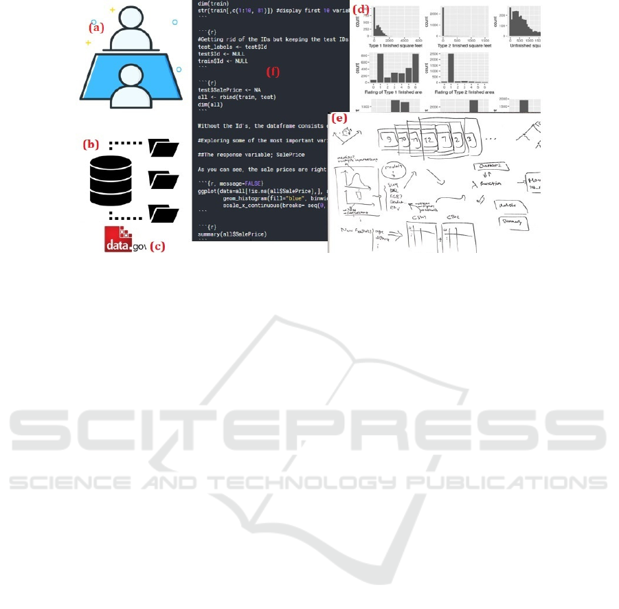
Figure 1: How data scientists currently design their big data analytics solutions.
is on storage, processing, and particularly the data
analysis and ML tasks.
Current data analytics tools rarely focus on the
improvement of end-to-end processes (Aalst, 2015).
To address this issue, better integration of data
science, data technology and process science is
needed (Aalst, 2015). Data science approaches tend
to be process agonistic whereas process science
approaches tend to be model-driven without
considering the evidence hidden in the data. Bringing
scalable process mining analytics to big data toolkits,
while enabling them to be easily tailored to
accommodate domain-specific requirements, is
required (Aalst, 2015). Tools filling these gaps would
be useful for end-users like data scientists, for the
discovery and exploration phase, to be able to model
the problem, extract insights/patterns, and develop
predictive and clustering models if it is feasible
before they need to involve software engineers.
We present our novel approach to addressing this
problem - Big Data Analytics Modeling Languages
(BiDaML) - a set of domain specific visual languages
(DSVLs) at different levels of abstraction (extended
from Khalajzadeh, 2019a), to capture and refine
requirements and specify different parts of the data
analytics process. Through these DSVLs, we aim to
make data analytics design more accessible to end-
users and facilitate dialogues with expert data
scientists and software engineers. BiDaML provides
better tool support and collaboration between
different users while improving the speed of
implementing data analytics solutions.
The rest of the paper is organized as follows. In
Section 2, the background and motivation of this
research are described with a real-world example of
traffic data analysis. Our approach is discussed in
Section 3 and evaluated in Section 4. A
comprehensive comparison to related work is
presented in Section 5. Finally, we draw conclusions
and discuss key future directions in Section 6.
2 MOTIVATING EXAMPLE
We discuss key data analytics steps and the different
types of communication needed between users in a
data analytics project. A real traffic data analysis
example integrating data from diverse data sources
including VicRoads’ SCATS traffic system (Sydney
Coordinated Adaptive Traffic System, an intelligent
transport system used to manage traffic signals in the
state of Victoria, Australia as well as other
states/cities) (VicRoads, 2018) is then demonstrated
to reflect the issues and some key challenges in the
process of data analytics.
2.1 Data Analytics Process Steps
The key steps that data scientists take to design their
solutions are illustrated in Figure 1. Business owners,
business analysts, data analysts and data scientists
need to have (a) several rounds of meetings and
interviews with domain experts and users; (b) acquire
datasets from different resources; (c) get access to
government information; (d) integrate all data items
with different format, analyze and visualize them; (e)
communicate with each other to discuss the analyses;
and (f) finally use different tools to design their
approaches and develop their models. However, there
is no unified language that allows to facilitate the
communication among domain experts, business
ENASE 2020 - 15th International Conference on Evaluation of Novel Approaches to Software Engineering
16

owner/analysts and software engineers and they need
to wait until their models are usable and deployable.
In this section, we will show an example of the traffic
data analysis to discuss some of the problems they
face during the solution design process.
2.2 Example: Traffic Data Analysis
For this real-world large project there was a need to
formally capture detailed requirements for a new
traffic data platform that would ingest a real-time
stream of traffic data received from VicRoads (the
Victorian road transport authority), integrate this with
other transport data sources, and support modeling
and visualization of the transport network at a state-
wide level. There were some issues arising in the
initiation of the project. The project leader and traffic
modeling experts identified the need for a big data
platform; however, without a background in software
engineering or familiarity with modern data science
tools, they were unable to determine whether the big
data technology stack offered by the software
outsourcing company was likely to meet their needs.
Moreover, the software outsourcing company lacked
understanding of the domain and thus did not
understand what tasks were required of them.
To overcome the communication difficulties, a
meeting was arranged between the project leader, the
traffic modeling expert, a data engineer/visualization
designer, the project team from the software
outsourcing company, and the eResearch high
performance computing services team. However, the
lack of a common language meant that
communication could only take place at a high-level
rather than at the level of detail necessary to initiate
direct technical action. The software outsourcing
company produced a plan for software they intended
to deploy; however, no plan existed for who would
monitor and maintain the software and systems after
deployment, such as responding to faults in real-time
data ingestion or adding support for new types of
data. To justify the cost and time investment into the
project, the project leader wanted to be able to reuse
the platform for related projects, such as a smart city.
However, it was unclear whether the work invested
into the design of the transport data platform could be
reused in other projects. Moreover, the software
outsourcing company lacked deep understanding of
the datasets and intended use of the platform, thus
were unable to begin work on the project. It was also
unclear who would maintain the computing
infrastructure, monitor data quality, and integrate new
data sources after the initial phase of the project.
We worked with transport researchers and used
BiDaML and toolset to specify the intended software
solution workflow. We performed in-depth
interviews with the project leader and traffic
modeling expert, then used BiDaML tool to
document the entire data analytics workflow
including data ingestion, transport modeling and
simulation, and result visualization. This allowed us
to assist in the formation of an alternative software
solution that made better use of the systems and
services already available. As BiDaML forces the
user to consider all phases of the project, the
modeling process helped reveal gaps in planning that
required attention. We will use the examples of the
diagrams we created throughout this paper.
2.3 Key Challenges
As illustrated, there is no trace back to the business
needs/requirements that triggered the project.
Furthermore, communicating and reusing existing big
data analytics information and models is shown to be
a challenge for many companies new to data
analytics. Users need to be able to collaborate with
each other through different views and aspects of the
problem and possible solutions. Current practices and
tools do not cover most activities of data analytics
design, especially the critical business requirements.
Most current tools focus on low-level data analytics
process design, coding and basic visualization of
results and they mostly assume data is in a form
amenable to processing. In reality, most data items
are in different formats and not clean or integrated,
and great effort is needed to source the data, integrate,
harmonize, pre-process and cleanse it. Only a few off-
the-shelf ML tools offer the ability for the data
science expert to embed new code and expand
algorithms and provide visualizations for their needs.
Data processing and ML tasks are only a small
component in the building blocks necessary to build
real-world deployable data analytics systems
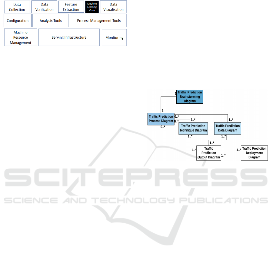
(Sculley, 2015). Figure 2 illustrates these tasks cover
a small part of data and ML operations and
deployment of models. Business and management
modeling tools usually do not support many key data
analytics steps including data pre-processing and ML
steps. There is a need to capture the high-level goals
and requirements for different users such as domain
expert, business analyst, data analyst, data scientist,
software engineer, and end-users and relate them to
low level diagrams and capture details such as
different tasks for different users, requirements,
objectives, etc. Finally, most of the tools covering ML
steps require data science and programming
knowledge to embed code and change features based
Visual Languages for Supporting Big Data Analytics Development
17
on the user requirements.
Figure 2: Data analytics steps (adapted from Sculley, 2015).
3 OUR APPROACH
Many current big data analytics tools, such as Azure
ML Studio, Amazon AWS ML and Google Cloud
ML, provide only low-level data science solution
design, despite many other steps being involved in
solution development (Khalajzadeh, 2019).
Therefore, a high-level presentation of the steps to
capture, represent, and communicate the business
requirements analysis and design, data pre-
processing, high-level data analysis process, solution
deployment and data visualization is required.
3.1 BiDaML Visual Language
We present BiDaML, a set of domain-specific visual
languages using six diagram types at different levels
of abstraction to support key aspects of big data
analytics:
- Brainstorming diagram provides an overview
of a data analytics project and all the tasks and sub-
tasks that are involved in designing the solution at a
very high level;
- Process diagram specifies the data analytics
processes/steps including key details related to the
participants (individuals and organizations),
operations, and data items in a data analytics project
capturing details from a high-level to a lower-level;
- Technique diagrams show the step by step
procedures, processes and techniques for each sub-
task in the brainstorming and process diagrams at a
low level of abstraction;
- Data diagrams document the data and artifacts
that are produced in each of the above diagrams in a
low level, i.e. technical AI based layer;
- Output diagrams define in detail the outputs
associated with different tasks e.g. output
information, reports, results, visualizations,
outcomes, etc.
- Deployment diagram depicts the run-time
configuration, i.e. the system hardware, the software
installed on it, and the middleware connecting
different machines to each other.
Figure 3 shows how our diagrams are connected
to each other from a high level to a low level. A
brainstorming diagram is defined for every data
analytics project. Then, at a lower level to include
more details and involve the participants, we use a
process diagram. Every operation in a process
diagram can be further extended by technique and
data diagrams, and then, the technique and data
diagrams are connected to a result output diagram.
Finally, the deployment diagram, defined for every
data analytics problem, models deployment related
details at a low level.
Figure 3: BiDaML diagrams overview for traffic data
analysis example.
3.1.1 Brainstorming Diagram
A data analytics brainstorming diagram’s scope
covers the entirety of a data analytics project
expressed at a high-level. There are no rules as to how
abstractly or explicitly a context is expanded. The
diagram overviews a data analytics project in terms
of the specific problem it is associated with, and the
task and subtasks to solve the specific problem. It
supports interactive brainstorming to identify key
aspects of a data analytics project such as its
requirements implications, analytical methodologies
and specific tasks.
Figure 4 (a) shows the visual notation used. It
comprises an icon representing the data analytics
problem, tasks which the problem is associated with,
a hierarchy of sub-tasks for each task, and finally the
specific information about sub-systems used or
produced.
We group the building blocks of an AI-powered
system into four groups: Domain and business-related
activities (BusinessOps); data-related activities
(DataOps); artificial intelligence and ML-related
activities (AIOps); and development and deployment
activities (DevOps). The BusinessOps covers domain
ENASE 2020 - 15th International Conference on Evaluation of Novel Approaches to Software Engineering
18
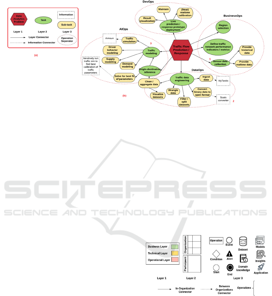
Figure 4: a) Brainstorming diagram notational elements and b) an example for the traffic data analysis problem.
and business knowledge and requirement gathering,
modeling and analysis. The DataOps includes data
collection/ingestion, data validation, cleansing,
wrangling, filtering, union, merge, etc. AIOps covers
feature engineering and model selection, model
training and tuning. Finally, DevOps covers model
integration and deployment, monitoring and serving
infrastructure. Figure 4 (b) depicts a high-level
brainstorming diagram for traffic data analysis
example. From this figure we can see that:
1) Sensor data collection will be done in both
historical and realtime formats;
2) SCATS converter is used to convert binary data to
an open format; and
3) Traffic modeling consists of traffic simulation,
driver behavior modeling, demand modeling, and
supply modeling.
3.1.2 Process Diagram
The key business processes in a data analytics
application are shown in a process diagram, whose
basic notation is shown in Figure 5. We adapt the
Business Process Modeling Notation (BPMN)
(OMG, 2011) to specify big data analytics processes
at several levels of abstraction. Process diagrams
support business process management, for both
technical users such as data analysts, data scientists,
and software engineers as well as non-technical users
such as domain experts, business users and
customers, by providing a notation that is intuitive to
business users, yet able to represent complex process
semantics.
In this diagram type, we use different “pools” for
different organizations and different “swim lanes” for
the people involved in the process within the same
organization. Different layers are also defined based
on different tasks such as business-related tasks
(BusinessOps), technical (DataOps and AIOps), and
operational tasks (DevOps and application-based
tasks). Data and artifacts produced and used in each
step can be shown as icons specific to the source and
type of data. Preparation of data items or different
events trigger other events and redirect the process to
the other users in the same or different pool.
Particular detailed activities or tasks performed by
different users and the order of them are represented
using rectangles and arrows. Diamonds show
different decision points that can adjust the path based
on conditions and double circles show unexpected
events that can change the process at any step.
Figure 5: Process diagram notational elements.
A high-level process diagram for our traffic data
analysis example is shown in Figure 6. In this, 1)
project starts when VicRoads, as the data provider,
provides historical data. 2) Domain knowledge is
shared with the software outstanding company to
provide the project’s cost estimate. 3) Technical lead
develops web-based interface. 4) eResearch services
provides big data storage/archival using MyTardis (A
large scale (research) data management/archival sys-
Visual Languages for Supporting Big Data Analytics Development
19
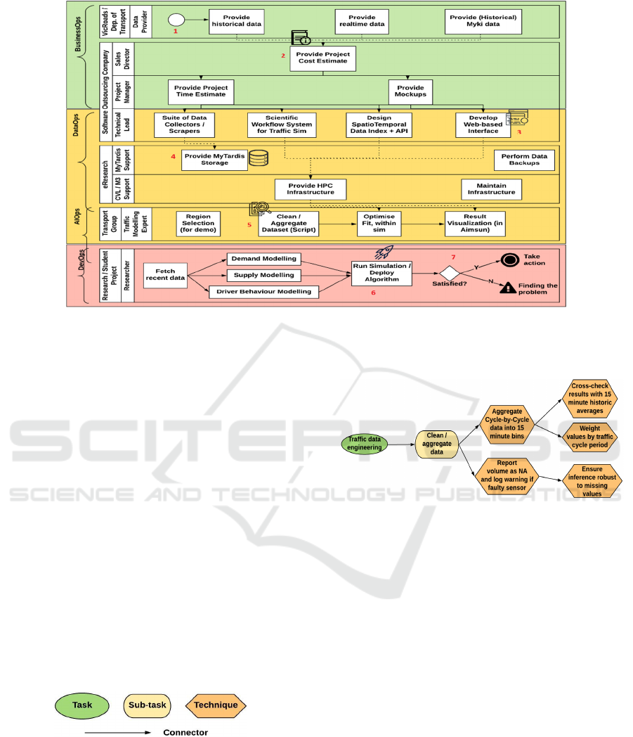
Figure 6: A process diagram example for the traffic data analysis problem.
tem developed by eResearch). 5) The extracted
insights are shared with the transport group in order
to clean and aggregate the dataset. 6) The researchers
run simulations and deploy algorithms, and finally 7)
if the final deployed models are satisfactory, then
further action to progress the project will be taken,
otherwise the problem needs to be found and
resolved. In this case, an alert needs to be triggered
and an issue tracking ticket assigned to the
responsible participant to improve the process and
consequently the outcome.
3.1.3 Technique Diagram
Data analytics technique diagrams extend the
brainstorming diagram to low-level detail specific to
different big data analytics tasks and sub-tasks. For
every sub-task, the process is broken down into the
specific stages and the technique used to solve a
specific sub-task specified. Figure 7 shows the
technique diagram notation.
Figure 7: Technique diagram notational elements.
In Figure 8, “Aggregate cycle-by-cycle data into
15 minutes bins” and “Report volumes as NA and log
warning if faulty sensor” are used as the
methods/techniques to clean/aggregate data, and then
the sub-techniques to solve challenges implementing
each of the methods are further specified. We can
create such diagrams for every task and sub-task in
brainstorming and process diagrams.
Figure 8: A technique diagram example for the traffic data
analysis problem.
3.1.4 Data Diagram
To document the data and artifacts consumed and
produced in different phases described by each of the
above diagrams, one or more low-level data
diagrams are created, using the notations shown in
Figure 9 (a). Data diagrams support the design of data
and artifacts collection processes. They represent the
structured and semi-structured data items involved in
the data analytics project in different steps. A high-
level data diagram can be represented by connecting
the low-level diagrams for different BusinessOps,
DataOps, AIOps, and DevOps.
A data diagram for our traffic analysis problem is
shown in Figure 9 (b). Here, data and artifacts related
to all tasks and sub-tasks in brainstorming and
process diagrams are connected to different data
entities. In this case, different data items, features,
outliers, the algorithms used, parameters related to
these algorithms, model created based on different
ENASE 2020 - 15th International Conference on Evaluation of Novel Approaches to Software Engineering
20
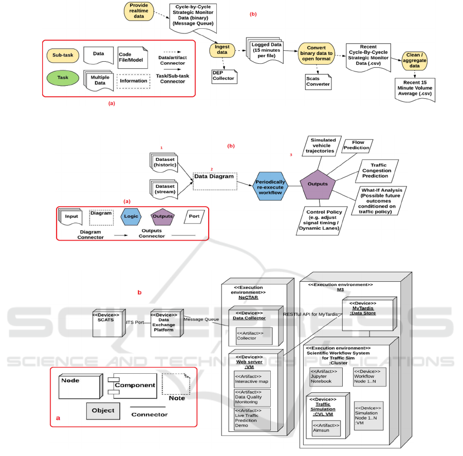
Figure 9: a) Data diagram notational elements and b) an example created for the traffic data analysis problem.
Figure 10: a) Output diagram notational elements and b) an example created for the traffic data analysis problem.
Figure 11: a) Deployment diagram notational elements and b) an example for the traffic data analysis problem.
algorithms, and the evaluation metrics used for the
model are captured for the AIOps entity. Data and
artifacts produced for other data entities such as
DataOps, DevOps, etc can be detailed and depicted
with other data diagrams.
3.1.5 Output Diagram
Output diagrams specify an individual technique in
more detail. This diagram type, shown in Figure 10
(a), reuses and merges the technique diagram and data
diagrams and adds information on the technique
(logic entity) and the data produced by it (as output
ports).
Figure 10 (b) shows an application in our traffic
data analysis example. Here we see (1) datasets used,
(2) part of the data diagram relating to the test for the
sampled data set and (3) a data analytics output
diagram defining the expected outputs from the
technique and data diagrams used for test and its
output. From this, we can see the outputs and reports
that can be extracted using current techniques and
data items, such as simulated vehicle trajectories,
flow prediction, traffic congestion prediction, etc.
3.1.6 Deployment Diagram
Since the deployment part follows the same rules as
Visual Languages for Supporting Big Data Analytics Development
21
the deployment process in software development, we
have adapted the deployment diagram from the
Unified Modeling Language (UML) (Ambler, 2004).
Our extended UML deployment diagram notation is
shown in Figure 11 (a).
In a deployment diagram, three-dimensional
boxes, known as nodes, represent the basic elements
of the software or hardware. Rectangles indicate the
objects in the system and the objects could be
contained within the nodes to represent the software
artifacts that are deployed and the components that
run on those nodes. Lines from one node to another
node specify the relationships between elements.
Figure 11 (b) shows an example deployment diagram
for our traffic data analysis problem, e.g. interactive
map, data quality monitoring, and live traffic
prediction demo are deployed on the web server, that
is in turn deployed within the NeCTAR environment
(an OpenStack-based cloud computing environment)
(NeCTAR, 2019).
3.2 BiDaML Support Tool
We have developed an integrated design environment
for creating BiDaML diagrams. The tool support aims
to provide a platform for efficiently producing
BiDaML visual models and to facilitate their creation,
display, editing, storage, code generation and
integration with other tools. We have used MetaEdit+
Workbench (MetaCase, n.d.) to implement our tool.
Using MetaEdit+, we have created the objects and
relationships defined as the notational elements for all
the diagrams, different rules on how to connect the
objects using the relationships, and how to define low
level sub-graphs for the high level diagrams.
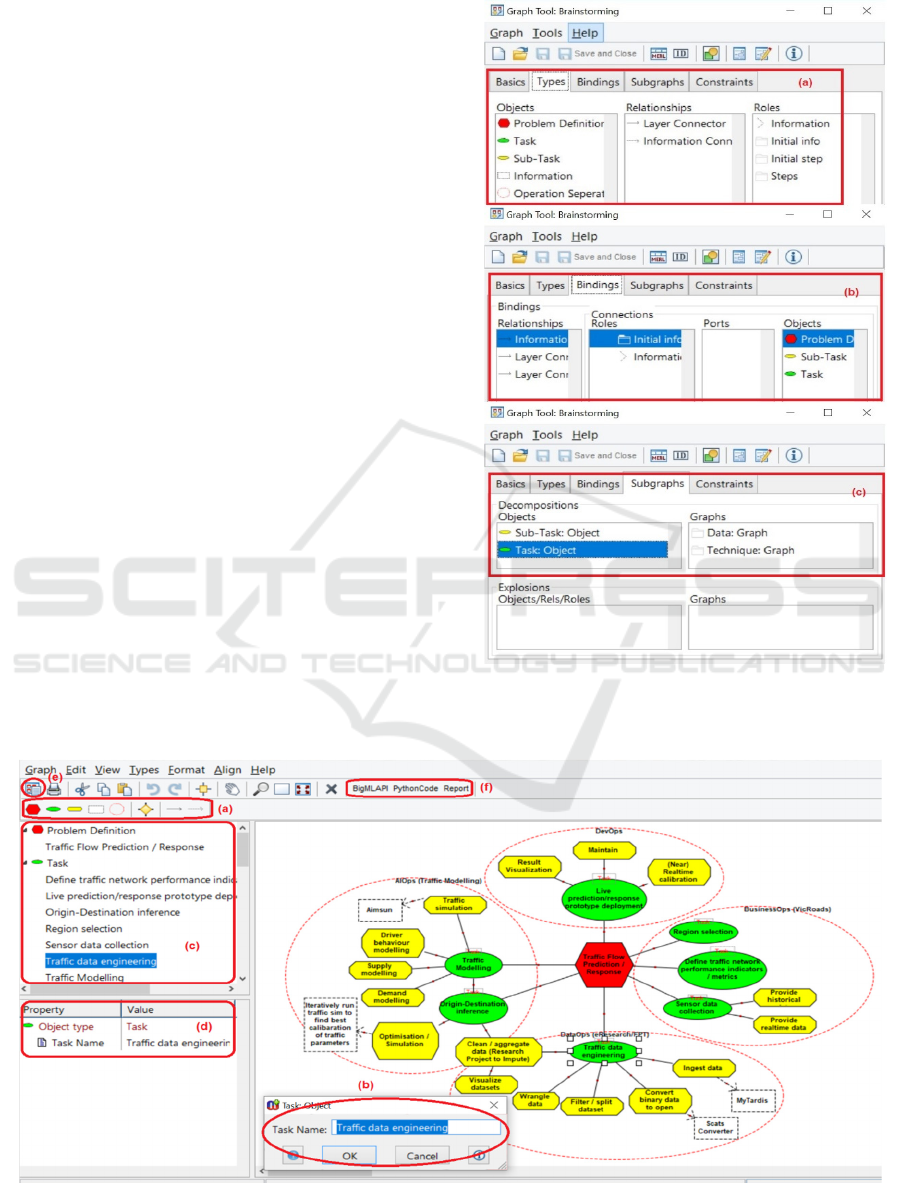
Figure 12: Defining brainstorming notational elements in
MetaEdit+.
Figure 13: An example of BiDaML tool for creating brainstorming diagram for the traffic data analysis problem.
ENASE 2020 - 15th International Conference on Evaluation of Novel Approaches to Software Engineering
22
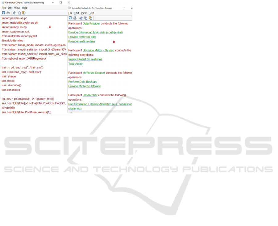
Figure 12 shows (a) how the objects, relationships,
and roles are defined, (b) how the rules for connecting
objects through relationships are defined, (c) how the
sub-graphs are connected to different objects of a
graph, for a brainstorming diagram. We have defined
these for all other diagrams.
Figure 14: A snippet of the a) python code generated from
the brainstorming diagram, and b) report generated from the
process diagram.
Figure 13 shows our tool used to create the
brainstorming diagram for our traffic analysis
example. Here, users (a) choose the notations of
objects/relationships and (b) modify the properties of
the object/relationship. Notations added to the
diagram are all listed (c) and details are shown by
clicking on the notations (d). Users can click on any
of the objects and create a sub-graph i.e., data,
technique, and output diagram for them. Finally, once
completed, (e) code generation features can be
embedded and modified and (f) and finally Python
code, BigML API recommendations and reports can
be generated for our traffic data analysis example in
this designed brainstorming diagram. Figure 14 (a) is
a snippet of the Python code generated from the
brainstorming diagram and Figure 14 (b) shows the
report generated from the process diagram.
4 EVALUATION
We have evaluated the usability and suitability of our
visual languages and tool suite in two ways (results
originally reported in Khalajzadeh, 2019a). The first
was an extensive physics of notations evaluation
(Moody, 2009). This was a useful end-user
perspective evaluation without having to involve a
large-scale usability trial. To understand how easy
BiDaML diagrams are to learn and use, we also
conducted a cognitive walkthrough using several
target domain expert end-users, including data
scientists and software engineers, as test subjects.
4.1 Physics of Notations Evaluation
Semiotic clarity specifies that a diagram should not
have symbol redundancy, overload, excess and
deficit. All our visual symbols in BiDaML have 1:1
correspondence to their referred concepts. Perceptual
discriminability is primarily determined by the visual
distance between symbols. All our symbols in
BiDaML use different shapes as their main visual
variable, plus redundant coding such as color and/or
textual annotation. Semantic transparency identifies
the extent to which the meaning of a symbol should
be inferred from its appearance. In BiDaML, icons
are used to represent visual symbols and minimize the
use of abstract geometrical shapes. Complexity
management restricts a diagram to have as few visual
elements as possible to reduce its diagrammatic
complexity. We used hierarchical views in BiDaML
for representation and as our future work, we will add
the feature for users to hide visual construct details
for complex diagrams. Cognitive integration
identifies that the information from separate diagrams
should be assembled into a coherent mental
representation of a system; and it should be as simple
as possible to navigate between diagrams. All the
diagrams in BiDaML have a hierarchical tree-based
structure relationship as shown in Figure 3.
Visual expressiveness defines a range of visual
variables to be used, resulting in a perceptually
enriched representation that exploits multiple visual
communication channels and maximizes
computational offloading. Various visual variables,
such as shape, color, orientation, texture, etc are used
in designing BiDaML visual symbols. Dual coding
means that textual encoding should also be used, as it
is most effective when used in a supporting role. In
BiDaML, all visual symbols have a textual
annotation. Graphic economy discusses that the
number of different visual symbols should be
cognitively manageable. As few visual symbols as
possible are used in BiDaML. Cognitive fit means
that the diagram needs to have different visual
dialects for different tasks or users. All the symbols
in BiDaML are usable for different users and tasks.
However, in the future, we will provide different
views for different users in our BiDaML support tool,
and users will be able to navigate between views
based on their requirements.
Visual Languages for Supporting Big Data Analytics Development
23
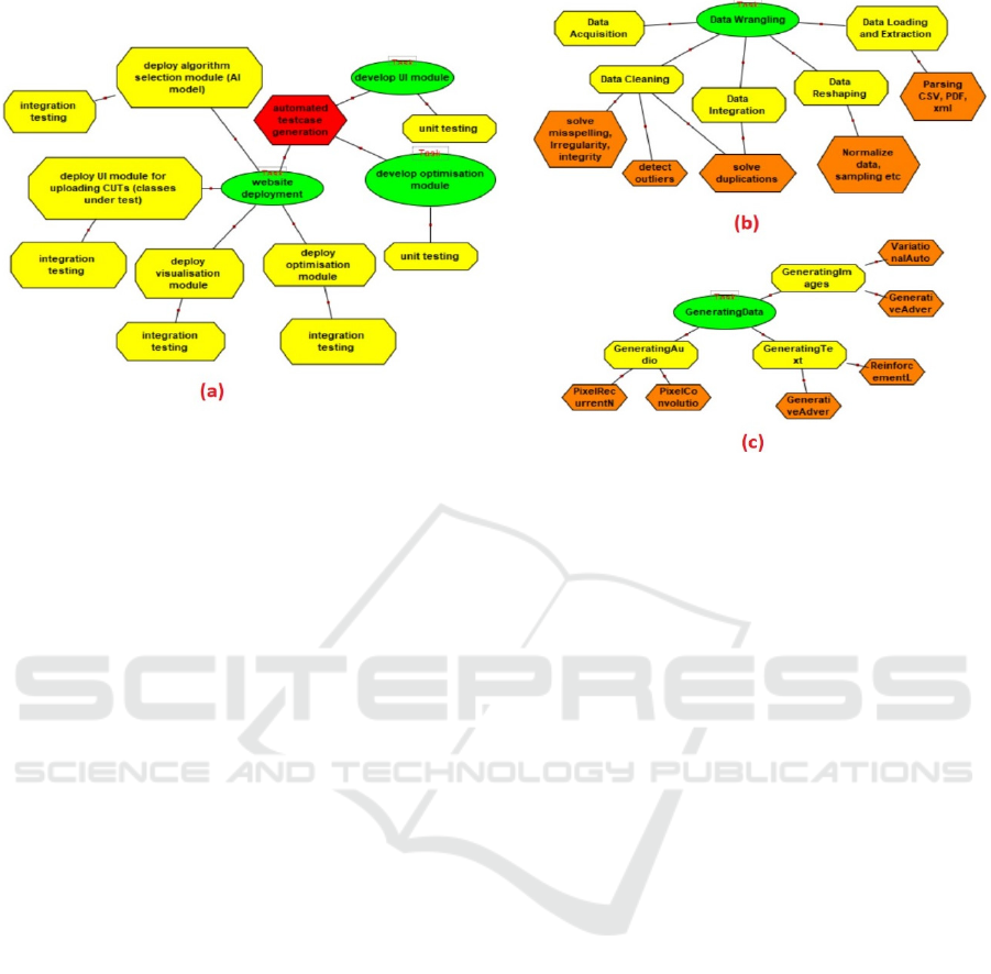
Figure 15: Example brainstorming and technique diagrams from our evaluators.
4.2 Cognitive Walkthrough
We asked 3 data scientists and 2 software engineers
(all experienced in big data analytics) to carry out a
task-based end-user evaluation of BiDaML. The
objective was to assess how easy it is to learn to use
the visual models and how efficiently it can solve the
diagram complexity problem. BiDaML diagrams
were briefly introduced to the participants who were
then asked to perform three predefined modeling
tasks. The first was to design BusinessOps, DataOps,
AIOps, or DevOps part of a brainstorming diagram
for a data analytics problem of their choice from
scratch. In the second, the subject was given a process
diagram and asked to explain it, comment on the
information represented and provide suggestions to
improve it. The third involved subjects designing a
technique diagram related to a specific task of the data
analytics problem they chose for the first part of the
evaluation. Figure 15 shows (a) devOps part of one of
the brainstorming diagrams and (b and c) two of the
technique diagrams that the data scientists/software
engineers drew to help explain their current work
tasks of (a) automated testcase generation (b) data
wrangling and (c) data augmentation.
Overall, users’ feedback indicated that BiDaML
is very straightforward to use and understand. Users
felt they could easily communicate with other team
members and managers and present their ideas,
techniques, expected outcomes and progress in a
common language during the project before the final
solution. They liked how different layers and
operations are differentiated. Moreover, they could
capture and understand business requirements and
expectations and make agreements on requirements,
outcomes, and results through the project. These
could then be linked clearly to lower-level data,
technique and output diagrams. Using this feedback
we have made some minor changes to our diagrams
such as the shape and order of some notations, and the
relationships between different objects.
However, several limitations and potential
improvements have also been identified in our
evaluations. Some users prefer to see technique and
data diagrams components altogether in a single
diagram, while some others prefer to have these
separate. Moreover, in the process diagram, some
users prefer to only see the operations related to their
tasks and directly related tasks. Finally, one of the
users wanted to differentiate between
tasks/operations that are done by humans versus a
tool. In future tool updates, we will provide different
views for different users and will allow users to
hide/unhide different components of the diagrams
based on their preference. Moreover, in our future
code generation plan, we will separate different tasks
based on whether they are conducted by humans or
tools. We will run a larger user evaluation with
business and domain expert end-users. The future
user study will be conducted in a more structured
manner, and the feedback will be collected
anonymously. Moreover, in order to evaluate the
usability of the current interface for new users of the
BiDaML tool, the participants will be given more
independent tasks. Finally, BiDaML will be
compared with the existing solutions, such as UML.
ENASE 2020 - 15th International Conference on Evaluation of Novel Approaches to Software Engineering
24

5 RELATED WORK
There are many data analytics tools available, such as
Azure ML Studio, Amazon AWS ML, Google Cloud
ML, and BigMl as reviewed in Khalajzadeh, 2019b.
However, these tools only cover a few phases of
DataOps, AIOps, and DevOps and none cover
business problem description, requirements analysis
and design. Moreover, since most end-users have
limited technical data science and programming
knowledge, they usually struggle using these tools.
Some DSVLs have been developed for supporting
enterprise service modeling and generation using
end-user friendly metaphors. An integrated visual
notation for business process modeling is presented
and developed in (Li, 2014) using a novel tree-based
overlay structure that effectively mitigates
complexity problems. MaramaAIC (Kamalrudin,
2017) provides end-to-end support between
requirements engineers and their clients for the
validation and improvement of the requirements
inconsistencies. SDLTool (Kim, 2015) provides
statistician end-users with a visual language
environment for complex statistical survey
design/implementation. These tools provide
environments supporting end-users in different
domains. However, they do not support data analytics
processes, techniques, data and requirements, and do
not target end-users for such applications.
Scientific workflows are widely recognized as
useful models to describe, manage, and share
complex scientific analyses and tools have been
designed and developed for designing, reusing, and
sharing such workflows. Kepler (Ludäscher, 2005)
and Taverna (Wolstencroft, 2013) are Java-based
open source software systems for designing,
executing, reusing, evolving, archiving, and sharing
scientific workflows to help scientists, analysts, and
computer programmers. VisTrails (Callahan, 2006) is
a Python/Qt-based open-source scientific workflow
and provenance management system supporting
simulation, data exploration and visualization. It can
be combined with existing systems and libraries as
well as your own packages/modules. Finally,
Workspace (Cleary, 2015), built on the Qt toolkit, is
a powerful, cross-platform scientific workflow
framework enabling collaboration and software reuse
and streamlining delivery of software for commercial
and research purposes. Users can easily create,
collaborate and reproduce scientific workflows,
develop custom user interfaces for different
customers, write their own specialized plug-ins, and
scale their computation using Workspace’s
remote/parallel task scheduling engine. Different
projects can be built on top of these drag and drop
based graphical tools and these tools are used in a
variety of applications and domains. However, they
only offer a limited number of data analysis steps and
no data analytics and ML capabilities and libraries.
Finally, some software tools implement
algorithms specific to a given graphical model such
as Infer.NET (Minka, 2010). This approach for
implementing data analytics techniques is called a
model-based approach to ML (Bishop, 2012). An
initial conceptualization of a domain specific
modeling language supporting code generation from
visual representations of probabilistic models for big
data analytics is presented in (Breuker, 2014) by
extending the analysis of the Infer.NET. However, it
is in very early stages and does not cover many of the
data analytics steps in real-world problems.
6 CONCLUSIONS
We have described a set of visual notations for
specifying data analytics project software
requirements and solutions. Our DSVLs, namely
BiDaML, are aimed at providing a similar modeling
framework for data analytics solution design as UML
does for software requirements and design. It is
comprised of six high- and low-level diagrammatic
types. These diagrams represent both data- and
technique-oriented components of a data analytics
solution design. A physics of notations analysis and a
cognitive walkthrough with several end-users were
undertaken to evaluate the usability of BiDaML. We
have also used our diagrams to model several
complex big data analytics problems.
Our future work includes providing multiple
view/elision support for large diagrams in our
BiDaML modeling tool. In addition, we see
considerable scope for providing back end integration
with other data analytics tools, such as Azure ML
Studio. Our tool can be used at an abstract level
during requirements analysis and design, and then
connected to existing software tools that operate at a
low level. Therefore, our DSVLs can be used to
design, implement and control a data analytics
solution. Our tool will support modeling and code
generation, together with collaborative work support
in the future. Since big data analysis has the same
steps, the code generation feature of our tool will
provide a set of templates for handling different
classes of systems in data analytics projects. These
will be leveraged to integrate our BiDaML tool with
other data analytics packages.
Visual Languages for Supporting Big Data Analytics Development
25

ACKNOWLEDGMENTS
Support from ARC Discovery Project DP170101932
and ARC Laureate Program FL190100035 is
gratefully acknowledged. We would also like to
acknowledge Prof. Hai L. Vu and Dr. Nam H. Hoang
from the Monash Institute of Transport Studies for
their collaboration, and thank the VicRoads
(Department of Transport, Victoria) for sharing the
transport data.
REFERENCES
Aalst, W. v. d., & Damiani, E. (2015). Processes Meet Big
Data: Connecting Data Science with Process Science.
IEEE Transactions on Services Computing, 8(6), 810-
819.
Ambler, S. (2004). The Object Primer: Agile Model-Driven
Development With Uml 2.0 3rd Edition: Cambridge
University Press
Bishop, C. M. (2012). Model-based Machine Learning.
Philosophical Transactions of the Royal Society A,
Mathematical, Physical and Engineering Sciences,
371(1984).
Breuker, D. (2014). Towards Model-Driven Engineering
for Big Data Analytics – An Exploratory Analysis of
Domain-Specific Languages for Machine Learning.
Paper presented at the 47th Hawaii International
Conference on System Science.
Callahan, S. P., Freire, J., Santos, E., Scheidegger, C. E.,
Silva, C. T., & Vo, H. T. (2006). VisTrails:
Visualization Meets Data Management. Paper
presented at the ACM SIGMOD international
conference on Management of data.
Cleary, P. W., Thomas, D., Bolger, M., Hetherton, L.,
Rucinski, C., & Watkins, D. (2015). Using Workspace
to Automate Workflow Processes for Modelling and
Simulation in Engineering. Paper presented at the 21st
International Congress on Modelling and Simulation.
https://research.csiro.au/workspace/
Kamalrudin, M., Hosking, J., & Grundy, J. (2017).
MaramaAIC: Tool Support for Consistency
Management and Validation of Requirements.
Automated Software Engineering, 24(1), 1-45.
Khalajzadeh, H., Abdelrazek, M., Grundy, J., Hosking, J.,
& He, Q. (2019a). BiDaML: A Suite of Visual
Languages for Supporting End-user Data Analytics.
Paper presented at the IEEE Big Data Congress, Milan,
Italy.
Khalajzadeh, H., Abdelrazek, M., Grundy, J., Hosking, J.,
& He, Q. (2019b). Survey and Analysis of Current End-
user Data Analytics Tool Support. IEEE Transactions
on Big Data, 5. doi:10.1109/TBDATA.2019.2921774
Kim, C. H., Grundy, J., & Hosking, J. (2015). A Suite of
Visual Languages for Model-Driven Development of
Statistical Surveys and Services. Journal of Visual
Languages and Computing, 26(C), 99-125.
Landset, S., Khoshgoftaar, T. M., Richter, A. N., &
Hasanin, T. (2015). A Survey of Open Source Tools for
Machine Learning with Big Data in the Hadoop
Ecosystem. Journal of Big Data, 2(24).
doi:https://doi.org/10.1186/s40537-015-0032-1
Li, L., Grundy, J., & Hosking, J. (2014). A Visual Language
and Environment for Enterprise System Modelling and
Automation. Journal of Visual Languages &
Computing, 25(4), 253-277.
Ludäscher, B., Altintas, I., Berkley, C., Higgins, D., Jaeger,
E., Jones, M., Zhao, Y. (2005). Scientific Workflow
Management and the Kepler System. Concurrency and
Computation: Practice and Experience, 18(10), 1039-
1065. doi:https://doi.org/10.1002/cpe.994
MetaEdit+ Domain-Specific Modeling tools – MetaCase.
Retrieved from https://www.metacase.com/
products.html
Minka, T., Winn, J., Guiver, J., & Knowles, D. (2010). Infer
.NET 2.4, 2010. Microsoft Research Cambridge.
Moody, D. (2009). The “Physics” of Notations: Toward a
Scientific Basis for Constructing Visual Notations in
Software Engineering. IEEE Transactions on Software
Engineering, 35(6), 756-779.
doi:https://doi.org/10.1109/TSE.2009.67
NeCTAR. (2019). ARDC’s Nectar Research Cloud.
Retrieved from https://nectar.org.au/cloudpage/
OMG. (2011). Business Process Model And Notation
(BPMN). Retrieved from https://www.omg.org/
spec/BPMN/2.0/
Portugal, I., Alencar, P., & Cowan, D. (2016). A
Preliminary Survey on Domain-Specific Languages for
Machine Learning in Big Data. Paper presented at the
IEEE International Conference on Software Science,
Technology and Engineering (SWSTE), Beer-Sheva,
Israel.
Rollins, J. B. (2015). Foundational Methodology for Data
Science. Retrieved from IBM Analytics:
Sapp, C. E. (2017). Preparing and Architecting for
Machine Learning. Retrieved from Gartner Technical
Professional Advice:
Sculley, D., Holt, G., Golovin, D., Davydov, E., Phillips,
T., Ebner, D., . . . Dennison, D. (2015). Hidden
Technical Debt in Machine Learning Systems. Paper
presented at the 28th International Conference on
Neural Information Processing Systems (NIPS),
Montreal, Canada.
VicRoads. (2018). SCATS. Retrieved from
https://www.vicroads.vic.gov.au/traffic-and-road-
use/traffic-management/traffic-signals/scats
Wolstencroft, K., Haines, R., Fellows, D., Williams, A.,
Withers, D., Owen, S., Goble, C. (2013). The Taverna
workflow suite: designing and executing workflows of
Web Services on the desktop, web or in the cloud.
Nucleic acids research, 41(1), 557-561.
ENASE 2020 - 15th International Conference on Evaluation of Novel Approaches to Software Engineering
26
