
Single-shot Acquisition of Cylindrical Mesostructure Normals using
Diffuse Illumination
Inseung Hwang, Daniel S. Jeon and Min H. Kim
KAIST School of Computing, South Korea
Keywords:
Cylindrical Mesostructure, Surface Normals, Diffuse Illumination.
Abstract:
Capturing high-quality surface normals is critical to acquire the surface geometry of mesostructures, such as
hair and metal wires with high resolution. Existing image-based acquisition methods have assumed a specific
type of surface reflectance. The shape-from-shading approach, a.k.a. photometric stereo, makes use of the
shading information by a point light, assuming that surfaces are perfectly diffuse. The shape-from-specularity
approach captures specular reflection densely, assuming that surfaces are overly smooth. These existing meth-
ods often fail, however, due to the difference between the presumed and the actual reflectance of real-world
objects. Also, these existing methods require multiple images with different light vectors. In this work, we
present a single-shot normal acquisition method, designed especially for cylindrical mesostructures on a near-
flat geometry. We leverage diffuse illumination to eliminate the reflectance assumption. We then propose a
local shape-from-intensity approach combined with local orientation detection. We conducted several experi-
ments with synthetic and real objects. Quantitative and qualitative results validate that our method can capture
surface normals of cylindrical mesostructures with high accuracy.
1 INTRODUCTION
Capturing the surface geometry of mesoscale objects,
such as textiles, brush hair, and metal wires, is de-
manding, and is often limited by the optical resolving
power of 3D scanning systems; i.e., the spatial res-
olution of many 3D scanning systems is limited by
the spatial resolution of the active illumination mod-
ule. To overcome the limitation of 3D scanning res-
olution, a hybrid approach that combines the low-
resolution geometry and the high-resolution surface
normals has been proposed and commonly used (Ne-
hab et al., 2005). For instance, we can obtain high-
frequency geometric details as surface normals us-
ing a high-resolution camera. These normals are then
transferred into low-frequency 3D geometry through
the backprojection of the normals, yielding a high-
resolution 3D model.
To this end, capturing high-quality surface nor-
mals is critical to achieving high-resolution 3D scan-
ning. Existing image-based acquisition methods rely
on some assumptions. More specifically, they assume
that the target object has a specific type of surface re-
flectance. For instance, the shape-from-shading ap-
proach, a.k.a. photometric stereo imaging (Wood-
ham, 1980), estimates surface normals by means of
the shading information. It captures multiple images
with a point light of known positions and decomposes
shading to light vectors and surface normals by as-
suming that the surface reflectance is perfectly dif-
fuse. Another popular approach is the shape-from-
specularity approach that captures specular reflections
very densely (Sanderson et al., 1988; Oren and Nayar,
1997). The surface normals are then estimated by de-
composing the specular reflections into the half-way
vectors and surface normals, assuming that surfaces
are overly smooth. However, these existing methods
to capture surface normals often fail due to the dif-
ference between the presumed and the actual surface
reflectance of real-world objects.
In this work, we present a single-shot normal ac-
quisition method that can capture high-quality surface
geometry of mesostructures. In particular, we target
cylindrical mesostructures on a flat geometry, such as
threads, brush hair, wires, etc. We first built an ex-
perimental setup for diffuse illumination, where 156
lights illuminate the target object. The diffuse illu-
mination setup removes the long-employed assump-
tion on the type of surface reflectance in our method.
We then propose a novel, local shape-from-intensity
method, combined with local orientation detection to
enhance robustness against noise. We derive the re-
Hwang, I., Jeon, D. and Kim, M.
Single-shot Acquisition of Cylindrical Mesostructure Normals using Diffuse Illumination.
DOI: 10.5220/0009181205610568
In Proceedings of the 15th International Joint Conference on Computer Vision, Imaging and Computer Graphics Theory and Applications (VISIGRAPP 2020) - Volume 4: VISAPP, pages
561-568
ISBN: 978-989-758-402-2; ISSN: 2184-4321
Copyright
c
2022 by SCITEPRESS – Science and Technology Publications, Lda. All rights reserved
561

lation between the unit variance of the input image
and the local height under diffuse illumination by for-
mulating a cylindrical model for orientation cues. Fi-
nally, we calculate normals from the orientation cues
through the local orientations of cylindrical shapes.
Our method does not assume any specific surface
reflectance and can robustly capture surface normals
of any diffuse and specular surfaces of various ob-
jects. The input of our method is a single-shot image
under diffuse illumination. This allows us to capture
normals efficiently.
2 RELATED WORK
Photometric Stereo. The shading information con-
tains incident light direction and surface normals. It
has been used to estimate surface normals by formu-
lating a linear equation of the cosine law, so-called
photometric stereo (Woodham, 1980). However, this
method is valid only with perfect diffuse reflectance.
Specular reflection often breaks the cosine law.
Several advanced photometric stereo methods
have been proposed to overcome the limitation by
specular reflection. Barsky and Petrou use four
images to perform photometric stereo (Barsky and
Petrou, 2003). Mallick et al. extract the pure dif-
fuse component in the color space, which is perpen-
dicular to incident light color (Mallick et al., 2005).
Ma et al. separate diffuse and specular reflection us-
ing the different polarization properties of both re-
flections (Ma et al., 2007). However, their method
has limitations as perfect diffuse specular separation
is impossible.
Shape from Specularity. Instead of relying on
shading information, many shape-from-specularity
methods have been proposed to capture surface nor-
mals. Chen et al. exploit specular highlights from
densely captured images in different illumination
(Chen et al., 2006). In their method, if a pixel is
a specular highlight, then the surface normal of the
point is calculated from light and view vectors. How-
ever, this method requires a set of many input images
with a condition that the entire surfaces should show
specular highlights more than one time. Specular re-
flection is supposed to be observed in a narrower an-
gle range than diffuse reflection; therefore, the meth-
ods that exploit specular reflection require many input
images.
Shape Acquisition from a Single Image. There
have been several attempts to obtain shape from a sin-
gle image using strong assumptions. Langer et al. pro-
posed the so-called dark-means-deep model (Langer
and B
¨
ulthoff, 2000). Dong et al. obtain spatial varying
reflectance properties and a normal map from a sin-
gle image using user interaction (Dong et al., 2011).
Barron et al. calculate shape, reflectance, and illumi-
nation from a single image (Barron and Malik, 2015).
However, the shape calculation of these methods as-
sumes that specific reflection cases to solve a severely
ill-posed problem. Recently, the methods to calcu-
late SVBRDF from a single image have been devel-
oped (Aittala et al., 2016; Li et al., 2017; Deschaintre
et al., 2018; Li et al., 2018). They exploit deep learn-
ing techniques. Existing single-shot normal acquisi-
tion methods require strong prior information, such as
user interaction, diffuse surface, or training data. In
contrast, our method requires only a single shot un-
der uniform illumination, measuring surface normals
directly without any prior or inference.
3 CAPTURING CYLINDRICAL
MESOSTRUCTURES
Overview. Our method employs a single image
taken under diffuse illumination as input. We then
standardize the input image with local mean and vari-
ance to make the input illumination-invariant. Next,
we detect the radius of the cylindrical shapes of
mesostructures using the scale-invariant Laplacian
detector. Futhermore, we detect the per-pixel orien-
tation of local geometry in the screen space. Lastly,
we compute surface normals using the cross product
after projecting image gradients to the local orienta-
tion. Figure 1 provides an overview.
Input
image
Intensity
standard.
Radius
detection
Normal
estimation
Orientation
detection
Output
normals
Figure 1: Normal estimation pipeline of our algorithm. We
calculate normal orientation using the Gabor filter and a
unit-variance intensity map from intensity statistics. The
final normal output comes from combining orientation and
a unit-variance intensity map.
3.1 Cylindric Image Formation
The target objects of our method are a set of cylin-
drical mesostructures that spread on a nearly flat
plane. In our research scope, we ignore the property
of surface colors, assuming that the surface albedo
is monochromatic. Our main objective is to cap-
ture high-frequency surface normals of cylindrical
mesostructures from an intensity image taken under
diffuse illumination.
VISAPP 2020 - 15th International Conference on Computer Vision Theory and Applications
562
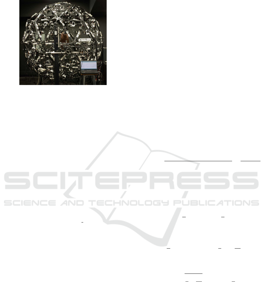
Figure 2: The light-stage system that we built to capture
the input image. The light stage consists of uniformly dis-
tributed 156 LED lights.
Input. Our method takes a single intensity image
as input. The image is taken under diffuse illumina-
tion, implemented by building a light stage. The light
stage includes 156 LED lights, which are uniformly
distributed over the sphere. Figure 2 presents our cap-
ture system. We then take a monochromatic intensity
image as input.
Image Formation Model. We first begin with the
traditional formulation of a cylinder shape (Glencross
et al., 2008). Suppose a cylinder of radius R exists
along the vertical y-axis. The height of the cylinder
comes out along the z-axis on the right-hand basis,
assuming an orthographic camera model. It can be
parameterized by the x-coordinates as follows:
h(x) =
R
2
−x
2
1
2
. (1)
The basic image formulation of our method fol-
lows the existing methods of the shape-from-intensity
approaches (Glencross et al., 2008; Beeler et al.,
2010). They assume that the locally lower points,
such as pores or wrinkles, are darker, and higher
points are lighter on the human face. Local heights
correspond to the high-pass filtered image in their
method. However, the high-pass filtered values are
intensity-variant; i.e., the heights estimated in the
bright region will be elongated relative to those es-
timated in the dark region. To achieve intensity-
invariant estimation, we propose a local adaptation
method of image intensity.
Under diffuse illumination, the image intensity
can be determined by the local height of the point.
Since a cylinder is symmetric, the points on the half
side of the cylinder have their correspondences in the
opposite side. Also, any points on the same latitude
level are assumed to have the same level of illumi-
nation. For half of the cylinder, the height increases
monotonically for each level of pixel positions. The
relation of the set of points that have the same inten-
sity to the height level is a bijective function. Now the
domain of the intensity function can change from the
position to the height:
I (x) = f (h (x)) , (2)
where I is the intensity of the position x, h is the height
of the position x, and f (·) is the unknown mapping
function from height to intensity (see Section 4.2 for
validation).
Since we use the linear camera signals without ap-
plying gamma correction, we assume that the above
mapping function f is linear as follows:
I (x) = c
1
·h(x) + c
0
, (3)
where c
0
and c
1
are unknown constants. The con-
stants c
0
and c
1
include all information of image for-
mation, such as surface albedo, incident light inten-
sity, camera exposure, linear camera response func-
tion, etc. To eliminate the constants c
0
and c
1
, we
standardize the image intensity as unit variance, a.k.a.
the z-score value, using a function z(·):
z(I (x)) =
(c
1
·h(x) + c
0
) −(c
1
·µ + c
0
)
c
1
·σ
=
h(x) −µ
σ
,
(4)
where µ is the mean of height h and σ is the stan-
dard deviation of height h. With the assumption of
cylindrical shapes of objects, the height function is
symmetric and thus the mean and variance can be cal-
culated for only a half period as follows:
µ =
1
R
Z
R
0
h(x)dx =
π
4
R. (5)
This integral can be solved as an area of a quarter of
a circle. The variance is
σ
2
=
1
R
Z
R
0
h(x)
2
dx −µ
2
=
2
3
R
2
−
π
2
16
R
2
. (6)
Finally, the height function of the z-score of image
and the cylinder radius can be written as follows:
h(x) =
r
2
3
−
π
2
16
Rz(I (x)) +
π
4
R. (7)
3.2 Estimating Mesostructures
Intensity Standardization. As mentioned earlier,
z-score maps can be converted to height maps using
Equation (7). However, the simple and global for-
mulation does not hold in a real scene; for instance,
the real-world object might not be a perfect plane and
might not be perfectly parallel to the sensor space due
to its shape geometry. In addition, even our experi-
mental setup is not perfect diffuse illumination due to
the sparsity of the lights.
Single-shot Acquisition of Cylindrical Mesostructure Normals using Diffuse Illumination
563

To mitigate these issues, we use the local z-score
map. First, the mean calculation in Equation (4) is
replaced with the Gaussian-weighted local mean µ
l
:
µ
l
(x, y) = (G
σ
∗I) (x, y) , (8)
where G is the Gaussian kernel, σ is the standard devi-
ation of the Gaussian kernel, and ∗ is the convolution
operator. Similarly, the local standard deviation σ
l
is
σ
l
(x, y) =
q
(G
σ
∗I
2
)(x, y) −((G
σ
∗I) (x, y))
2
. (9)
The local unit-variance value can then be expressed
as
˜
I (x, y) =
I (x, y) −µ
l
(x, y)
σ
l
(x, y)
. (10)
The local unit-variance value is invariant to low-
frequency change of local intensity and irregular light
conditions. The smaller sigma makes the local unit-
variance more independent of local illumination dif-
ference, but an overly small value can lose local statis-
tics. We select a sigma level that has a larger value
than the diameters of the cylindric objects in the im-
age.
Radius Detection. The radius of the cylinder is re-
quired to calculate the height map from the local
unit-variance map. Assuming that the same cylindric
shapes exist in the scene, only a radius value in the
screen coordinates is required to calculate the surface
normal. We obtain the radius of the cylinder from
the blob size using the Laplacian of Gaussian (LoG)
blob detection (Lindeberg, 1998) based on the hills
and valleys model of (Langer and B
¨
ulthoff, 2000). A
hill means a high area in the cylinder, which is a bright
area in the image. Valleys are the opposite of hills.
The LoG blob detection algorithm detects both areas,
and thus we use both blob scale results.
In detail, we apply the LoG blob detection first to
the local unit-variance map. Owing to the maximum
response of the LoG operation, the blob size is multi-
plied by
√
2. The detected position and blob size can-
not be used directly as the numbers of blobs in hills
and valley are different. A blob is identified as either
a hill or a valley by the z-score of the blob position
in the local unit-variance map. If the z-score is larger
than a threshold, the blob is in the hill. Otherwise, the
blob is in the valley.
Orientation Detection. In our cylinder model, the
gradient of the image is perpendicular to the cylinder
orientation (the height axis of the cylinder). However,
the gradient is not perfectly perpendicular to the ori-
entation in the real scene. The derivation operation
to calculate gradients is sensitive to noise in nature.
Since we are targeting small-scale objects of a small
radius, our method is very sensitive to noise in gradi-
ents. To mitigate the noise problem, we exploit direc-
tional derivatives using the cylinder orientation from
the larger-scale operation.
We first employ the Gabor filter to find the orienta-
tion of the cylinders. The Gabor filter has been com-
monly used in the orientation estimation of objects
with a small cylindrical geometry, such as hair (Paris
et al., 2004; Jakob et al., 2009; Nam et al., 2019). We
estimate the orientations of cylinders by detecting the
maximum amplitude of the Gabor filter.
θ
∗
(x, y) = argmax
θ
|
(F
θ
∗I) (x, y)
|
, (11)
where F
θ
is the Gabor filter that is tilted at the θ angle
from the x-axis and θ
∗
is the calculated orientation
map.
We compute the orientation map by convolving
the input image with predefined angle candidates in a
certain angle resolution. We apply the Gabor filters of
different angles in 5-degree intervals. We then apply a
median filter of 3×3 to suppress noise. However, the
angle values have a period; the median filter cannot
be used directly. Therefore, we first apply the median
filters to three different angle ranges as follows:
m
n
(x, y) = mod
median
(s,t)∈S
xy
(θ
∗
n
(s, t)), π
, (12)
where m
n
is the median filter result where the range
shifted
nπ
3
radians, n is 0, 1 or 2, S
xy
is a 3×3 window
of the median filter, and the shifted angle values as
θ
∗
n
(x, y) = mod
θ
∗
(x, y) −
nπ
3
, π
+
nπ
3
. (13)
We obtain the cosine value of the angle difference
to derive the angle pair with high confidence that has
the smallest difference:
C
i j
(x, y) = cos (m
i
(x, y) −m
j
(x, y)). (14)
where i 6= j.
We choose the pair that has the largest absolute
cosine value, not the signed cosine value, as the di-
rection, and the opposite direction is the same for the
cylinder orientation:
(i
∗
(x, y), j
∗
(x, y)) = argmax
i. j
C
i j
(x, y)
s.t. i 6= j.
(15)
We use the mean angle of the pair of the median
value. When the mean angle is calculated, the direc-
tion and the opposite direction yield different values.
We compute the mean angle that has a smaller differ-
ence with the median value.
θ
i j
(x, y) =
(
m
i
(x,y)+m
j
(x,y)
2
if C
i j
(x, y) ≥ 0
m
i
(x,y)+m
j
(x,y)+π
2
otherwise
(16)
VISAPP 2020 - 15th International Conference on Computer Vision Theory and Applications
564

Orientation
x
y
ˆ
d
,
xy
hh
ˆ
d
h d
ˆ
Figure 3: The image gradients are projected to the direction
perpendicular to the cylinder orientation, suppressing noise
in the calculated gradients.
Finally, the median angle estimated by the Gabor filter
is given as follows:
θ
med
(x, y) = θ
i
∗
(x,y), j
∗
(x,y)
(x, y). (17)
Normal Estimation. The final step is to calculate
normals from the unit-variance intensity map and the
orientation map. First, we obtain the local height map
from the local z-score map.
h(x, y) =
r
2
3
−
π
2
16
R
˜
I (x, y) (18)
The coefficients of the local z-score values are inher-
ited from Equation (7). The constant term in Equa-
tion (7) is not necessary as we use the derivation of
the local height map to compute the normal map.
Next, we obtain the directional derivatives that are
perpendicular to the cylinder orientations. We calcu-
late partial derivatives of the x - and y-axis using the
Sobel filter:
h
x
(x, y) =
∂h(x, y)
∂x
, h
y
(x, y) =
∂h(x, y)
∂y
. (19)
The gradients are then projected to the lines that are
perpendicular to the cylinder orientations by the dot
product:
h
d
(x, y) =
h
x
(x, y)
h
y
(x, y)
·
ˆ
d(x, y), (20)
where
ˆ
d(x, y) =
sinθ
∗
(x, y) −cos θ
∗
(x, y)
T
is the
direction that is perpendicular to the cylinder orienta-
tion, and θ
∗
is the angle of the cylinder orientation
from the x-axis. The projection mechanism is de-
picted in Figure 3.
Finally, we obtain the surface normals from the
cylinder directions and the derivatives. The tangent
vector
ˆ
t of the normal vector is
ˆ
t(x, y) =
t(x, y)
k
t(x, y)
k
, (21)
where
t(x, y) =
sinθ
∗
(x, y) −cos θ
∗
(x, y) h
d
(x, y)
T
.
(22)
And its bitangent vector
ˆ
b is
ˆ
b(x, y) =
cosθ
∗
(x, y) sin θ
∗
(x, y) 0
T
. (23)
The bitangent vector is the orientation that makes the
normal orientation to the camera placement. Finally,
the normal map
ˆ
n can be calculated as follows:
ˆ
n(x, y) =
ˆ
t(x, y) ×
ˆ
b(x, y). (24)
4 RESULTS
In this section, we validate our normal estimation
algorithm by providing quantitative and qualitative
analyses of experiment results with synthetic ground
truth and real data. We implemented our algorithm in
MATLAB without code optimization and computed
in Intel i7-7700K CPU and 32GB memory. For an
image with a resolution of 256×256, our algorithm
took approximately 0.63 seconds in total.
4.1 Evaluation on Real Data
Experimental Details. For real scene experiments,
we built a light stage with 156 LED lights uniformly
distributed over the sphere to capture an object. The
LED lights (CXA1512-0000-000N00N20E1) have a
flux of 1650lm, a power 12.6W, and a correlated color
temperature of 6500K. The lights are located at the
edge and vertex of the subdivision of an icosahedron.
The diameter of a sphere is 2.6m. We use a machine-
vision camera (GS3-U3-123S6C-C) with a resolution
of 4096×3000 and a pixel pitch size of 3.45µm. To
achieve the orthographic camera assumption of our
image formation, we employ a lens with a focal length
of 35mm and crop the 256×256 center region of the
captured image, of which the field of view is 1.45
◦
.
Qualitative Comparison. We compared our re-
sults with four existing methods: photometric stereo,
mesostructure from specularity (Chen et al., 2006),
and two deep learning-based single image normal ac-
quisition methods (Ye et al., 2018; Deschaintre et al.,
2018). For photometric stereo and mesostructure
from specularity, we captured 60 images with differ-
ent light positions and calibrated them using a mirror
sphere. As Deschaintre’s method requires a captured
image under a flashlight, we captured an image with
a single light. We experimented with various surfaces
for our model. They include diffuse surfaces (flower
Single-shot Acquisition of Cylindrical Mesostructure Normals using Diffuse Illumination
565
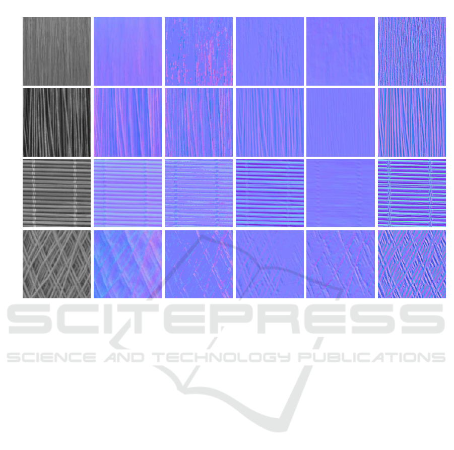
Input Photometric stereo Chen et al. Ye et al. Deschaintre et al. Ours
Paint brush
Flower wire
Bamboo mat
Skein
Figure 4: We compare the results of our normal estimation method with other existing methods. Other methods fail to estimate
thin cylindrical structures of surfaces.
wire, bamboo mat), thin speucular structures (brush),
and complex structures (skein).
Figure 4 shows the captured images and recon-
structed normal maps. Photometric stereo measures
the overall normal map well but fails in capturing
high-frequency surface orientation. Deep learning-
based methods show low-quality normal map results
for thin cylindrical structures. These methods re-
quire a single input image with specular reflection
under a point light. For transparent surfaces and
thin cylindrical shapes, these methods fail to capture
high-frequency details because specular reflection oc-
curs in arbitrary directions by refraction and occlu-
sion. This phenomenon reduces the surface orienta-
tion cues of the light direction. Compared with other
existing methods, our method shows the best quality,
achieving fine-level details of surface orientations of
mesostructures.
4.2 Quantitative Evaluation with
Simulation
Here we validate our cylinder model by comparing
the ground truth normals and reconstructed normals
from synthetic images. We rendered an array of cylin-
ders in a uniform illumination using the Mitsuba ren-
derer. The GGX microfacet distribution (Walter et al.,
2007) was used for a specular reflectance model. All
cylinders have the same radius and reflection param-
eters, including albedo and specular roughness, by
changing α parameter of the GGX model. We eval-
uate our algorithm with various roughness to validate
the performance of our algorithm.
Figures 5(a) and (b) present rendered synthetic in-
put images and the ground truth normal maps of the
same geometry. Figures 5(c) and (d) show the nor-
mal maps yielded by our method and the angle differ-
ence between our results and the ground-truth normal
maps. Almost every position over the mesostructures
presents smaller differences than 20 degrees. How-
ever, we found that there are large angle differences
in the deepest points in the valley. These points are
not differentiable and thus the finite differences lead
to suboptimal results.
Figure 5(e) shows the relation between the
ground-truth height and the unit variance intensity
values. It shows that the height and the unit-variance
intensity have a linear relation for a wide range of
roughness. When the surface is a mirror, the sur-
face makes only two values that are the high inten-
sity from the specular reflection and the low intensity
VISAPP 2020 - 15th International Conference on Computer Vision Theory and Applications
566
(a) Input
(d) Angle difference map (e) Height-intensity relation
(b) Ground-truth normal map
(c) Estimated normal map
0 0.5 1
Height
-4
-3
-2
-1
0
1
2
Unit-variance intensity
Synthetic image
Our model
0°
10°
20°
30°
40°
50°
0 0.5 1
-4
-3
-2
-1
0
1
2
Height
Unit-variance intensity
Synthetic image
Our model
0 0.5 1
-4
-3
-2
-1
0
1
2
Height
Unit-variance intensity
Synthetic image
Our model
4.0=α
6.0=α
8.0=α
0°
10°
20°
30°
40°
50°
0°
10°
20°
30°
40°
50°
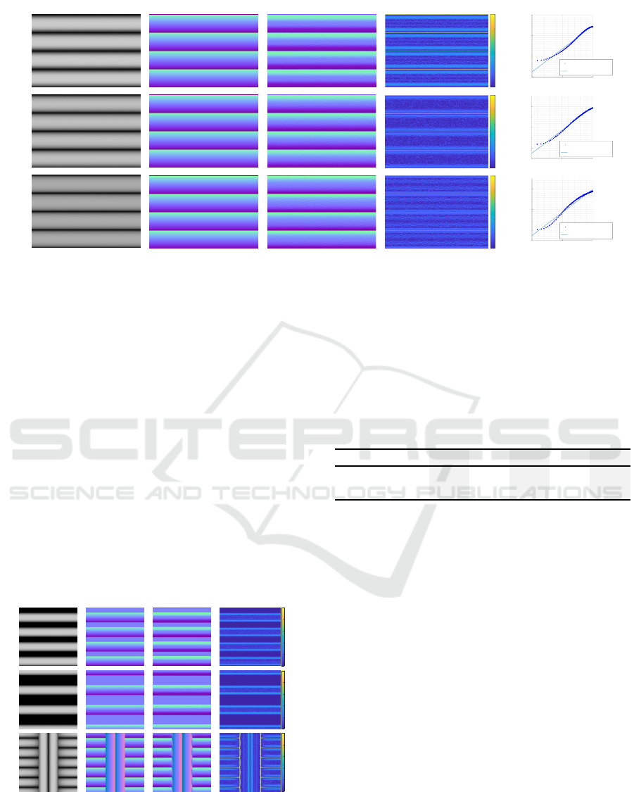
Figure 5: Quantitative evaluation with the synthetic ground-truth dataset. (a) Input image of cylinders (without gaps) rendered
with the Mitsuba renderer. (b) Ground-truth normals of the same geometry (c) Estimated normals. (d) The angle difference
between our results and the ground truth. (e) The comparison between the intensities and the estimated height levels.
from the occlusion around cylinders. If the surface
becomes rougher, the relation of the height and the
unit-variance intensity become closer to the linear re-
lation. However, the intensity of the top of the cylin-
der is weaker than near points where the surface is dif-
fuse because the top of the cylinder does not have in-
terreflection. Table 1 shows the average angle differ-
ence in each image. The average angle difference is
smaller than 15 degrees in the tested roughness range.
The average differences decrease when the roughness
becomes larger, but they increase again when the sur-
face is highly diffuse. Figure 6 includes the results
for different alignment of cylinders, such as varying
on the inter-cylinder distance and crossing. All cylin-
ders have the fixed roughness (α=0.4). The intervals
among cylinders are set to half of a cylinder and a
cylinder. The background shown in the intervals is
(a) Input (d) Angle difference(b) GT normal (c) Estimated normal
0°
10°
20°
30°
40°
50°
Interval: RInterval: 2RCrossing
0°
10°
20°
30°
40°
50°
0°
10°
20°
30°
40°
50°
Figure 6: Quantitative evaluation with the synthetic ground-
truth dataset which have inter-cylinder distance and cross-
ing. The intervals among cylinders are set to half of a cylin-
der and a cylinder. (a) Input image. (b) Ground-truth nor-
mals. (c) Estimated normals. (d) The angle difference be-
tween our results and the ground truth.
set to the infinite distance, yielding no value of ren-
dering. Therefore, we exclude the values at the infi-
nite distance from the calculation. The results of the
inter-cylinder gap and crossing also show small dif-
ferences, compared with the ground truth.
Table 1: Average angle errors of our method with different
surface roughness parameters.
Roughness (α)
0.4 0.5 0.6 0.7 0.8
Mean error (deg)
10.64 9.49 8.57 8.26 8.91
Std. dev (deg)
8.49 8.23 7.88 7.51 7.15
5 LIMITATIONS
Our method is not free from limitations. First, our
method presents a suboptimal performance in captur-
ing normals for highly specular objects such as a mir-
ror or highly diffuse objects. As shown in our syn-
thetic experiments, the perfect mirror surfaces present
only two intensity levels: light existing and light oc-
cluded. For perfect diffuse surfaces, the interreflec-
tion becomes larger where the height is smaller, while
our relation conversion is valid on the top of cylin-
ders. This breaks our assumption. These surfaces of
extreme reflectances require a roughness estimation
or interreflection calculation. Second, the processing
of string crossing areas of our method could be devel-
oped further. If the texture has many cross-sections,
the ambiguity in detecting surface orientations might
become severely ill-posed when applying for the Ga-
bor filter. Third, diffuse illumination is hard to ac-
quire. We used a large light stage to obtain diffuse
illumination. Single-shot acquisition of cylindrical
Single-shot Acquisition of Cylindrical Mesostructure Normals using Diffuse Illumination
567

mesostructure normals with a point light or without
any light condition are possible areas of future work.
6 CONCLUSIONS
We have presented a normal map acquisition method
primarily designed for mesoscale cylindric objects us-
ing a single input image. We have discovered that
mesoscale geometry can provide local intensity statis-
tics to solve practical issues in the existing shape-
from-intensity approach. We showed that the rela-
tion of the local height and unit-variance intensity un-
der diffuse illumination of the light stage. We cal-
culated the normal maps from the local unit-variance
values and the detected cylindric orientations from
a single image. We validated that our method con-
sistently outperforms existing methods for capturing
high-frequency details of the surface orientation of
both specular and diffuse objects in the real world.
ACKNOWLEDGEMENTS
Min H. Kim acknowledges Korea NRF grants
(2019R1A2C3007229, 2013M3A6A6073718) and
Cross-Ministry Giga KOREA Project (GK17P0200).
REFERENCES
Aittala, M., Aila, T., and Lehtinen, J. (2016). Reflectance
modeling by neural texture synthesis. ACM Trans.
Graph., 35(4):65.
Barron, J. T. and Malik, J. (2015). Shape, illumination, and
reflectance from shading. IEEE TPAMI, 37(8):1670–
1687.
Barsky, S. and Petrou, M. (2003). The 4-source photometric
stereo technique for three-dimensional surfaces in the
presence of highlights and shadows. IEEE TPAMI,
25(10):1239–1252.
Beeler, T., Bickel, B., Beardsley, P., Sumner, B., and Gross,
M. (2010). High-quality single-shot capture of facial
geometry. In ACM Trans. Graph., volume 29, page 40.
Chen, T., Goesele, M., and Seidel, H.-P. (2006). Mesostruc-
ture from specularity. In Proc. IEEE CVPR 2006, vol-
ume 2, pages 1825–1832.
Deschaintre, V., Aittala, M., Durand, F., Drettakis, G., and
Bousseau, A. (2018). Single-image svbrdf capture
with a rendering-aware deep network. ACM Trans.
Graph., 37(4):128.
Dong, Y., Tong, X., Pellacini, F., and Guo, B. (2011). App-
gen: interactive material modeling from a single im-
age. In ACM Trans. Graph., volume 30, page 146.
Glencross, M., Ward, G. J., Melendez, F., Jay, C., Liu, J.,
and Hubbold, R. (2008). A perceptually validated
model for surface depth hallucination. In ACM Trans.
Graph., volume 27, page 59.
Jakob, W., Moon, J. T., and Marschner, S. (2009). Capturing
hair assemblies fiber by fiber. In ACM Transactions on
Graphics (TOG), volume 28, page 164. ACM.
Langer, M. S. and B
¨
ulthoff, H. H. (2000). Depth discrimina-
tion from shading under diffuse lighting. Perception,
29(6):649–660.
Li, X., Dong, Y., Peers, P., and Tong, X. (2017). Model-
ing surface appearance from a single photograph using
self-augmented convolutional neural networks. ACM
Trans. Graph., 36(4):45.
Li, Z., Xu, Z., Ramamoorthi, R., Sunkavalli, K., and Chan-
draker, M. (2018). Learning to reconstruct shape
and spatially-varying reflectance from a single image.
ACM Trans. Graph., page 269.
Lindeberg, T. (1998). Feature detection with automatic
scale selection. IJCV, 30(2):79–116.
Ma, W.-C., Hawkins, T., Peers, P., Chabert, C.-F., Weiss,
M., and Debevec, P. (2007). Rapid acquisition of spec-
ular and diffuse normal maps from polarized spherical
gradient illumination. In Eurographics, page 183.
Mallick, S. P., Zickler, T. E., Kriegman, D. J., and Bel-
humeur, P. N. (2005). Beyond lambert: Reconstruct-
ing specular surfaces using color. In Proc. IEEE
CVPR 2005, volume 2, pages 619–626. Ieee.
Nam, G., Wu, C., Kim, M. H., and Sheikh, Y. (2019).
Strand-accurate multi-view hair capture. In Proc.
IEEE CVPR 2019, pages 155–164.
Nehab, D., Rusinkiewicz, S., Davis, J., and Ramamoorthi,
R. (2005). Efficiently combining positions and nor-
mals for precise 3d geometry. ACM Trans. Graph.,
24(3):536–543.
Oren, M. and Nayar, S. K. (1997). A theory of specular
surface geometry. IJCV, 24(2):105–124.
Paris, S., Brice
˜
no, H. M., and Sillion, F. X. (2004). Cap-
ture of hair geometry from multiple images. In ACM
Trans. Graph., volume 23, pages 712–719. ACM.
Sanderson, A. C., Weiss, L. E., and Nayar, S. K. (1988).
Structured highlight inspection of specular surfaces.
IEEE TPAMI, 10(1):44–55.
Walter, B., Marschner, S. R., Li, H., and Torrance, K. E.
(2007). Microfacet models for refraction through
rough surfaces. In Eurographics, pages 195–206.
Woodham, R. J. (1980). Photometric method for determin-
ing surface orientation from multiple images. Optical
engineering, 19(1):191139.
Ye, W., Li, X., Dong, Y., Peers, P., and Tong, X. (2018).
Single image surface appearance modeling with self-
augmented cnns and inexact supervision. In Computer
Graphics Forum, volume 37, pages 201–211.
VISAPP 2020 - 15th International Conference on Computer Vision Theory and Applications
568
