
Towards Automatic CAD Modeling from 3D Scan Sketch based
Representation
Abd El Rahman Shabayek
1
, Djamila Aouada
1
, Kseniya Cherenkova
1,2
and Gleb Gusev
2
1
CVI
2
, Interdisciplinary Centre for Security, Reliability, and Trust, University of Luxembourg, Luxembourg
2
Artec 3D, Luxembourg
Keywords:
Scan2CAD, Sketch based Modeling, Automated Modeling.
Abstract:
This paper proposes a novel approach to convert a 3D scan to its CAD counterpart. The objective is to extract
intermediate sketch planes that well represent the input scan and are close enough to the original design intent.
These sketches can then be easily converted into CAD models automatically due to their faithful representa-
tion of the input geometry. One objective is to avoid incorporating user/company dependent content in the
CAD reconstruction process. The intermediate representation shall be directly supported in any CAD envi-
ronment to boost the designer’s work without the need of supplementary (model conversion, automatic feature
recognition) steps. Nowadays, it is common to digitize an object and reconstruct its geometric primitives.
However, this reconstruction contains only geometry. In literature, the final goal might be met by recovering
the modeling tree itself, by means of automatic feature recognition, and converting to the proper format of a
specific CAD software package. However, the constructed tree and its conversion introduce issues in the re-
construction process. The definition of an exact modeling tree, and the production of a meaningful final CAD
model are rather hard to obtain. This imposes a rather inefficient working method, thereby heavily impacting
the designer’s modeling skills.
1 INTRODUCTION
Converting an input 3D scan to a Computer Aided
Design (CAD) model involves extracting enough in-
formation to reproduce that scan. It can be applied
to any scanned object like manufactured, chemical or
biological products. There are various reasons to re-
verse engineer a scan such as developing interfaces
for system interoperability, developing stricter secu-
rity protocols, fixing product flaws, reducing costs,
etc. There is no single process to reverse a scan to
its original CAD (Barh and Azevedo, 2018).
Existing methods tend to tackle the scan to CAD
conversion problem from a primitive fitting point of
view (Kaiser et al., 2019; Buonamici and Carfagni,
2016). This approach is a natural consequence of the
designers’ community common practice in design-
ing their products where basic geometric primitives
(such as planes, spheres, cylinders and cones) are at
the heart of it. These methods can be classified into
constrained primitive fitting (Kaiser et al., 2019; Patil
et al., 2017; Kov
´
acs et al., 2015) and learning-based
primitive fitting (Li et al., 2019; Ranftl and Koltun,
2018; Brachmann et al., 2017). There are also recent
learning-based approaches that look for the similarity
between scans and CADs to finally retrieve the appro-
priate CAD model (Dahnert et al., 2019; Avetisyan
et al., 2019) or look for specific feature or repetition
patterns (Gauthier et al., 2019).
The constrained fitting approaches have to deal
with complexities of geometrical constraints, correct
boundary representations and accurate parametriza-
tion. Besides that, free-form surfaces are not well
addressed or constrained (Kaiser et al., 2019) while
for learning-based approaches, the basic assumption
is the existence of a large database of scans and/or
CADs which is not always available.
This paper addresses the problem from a different
point of view; the scan can be converted to a set of
one or more reference sketches that originate a CAD
model. This point of view is closer to the design
intent of an object modeled in terms of its 2D pro-
file(s). This paper targets objects rather than com-
plete scenes. The core idea is to have an interme-
diate standard representation which 1) preserves (to
some extent) the design intent and 2) is understood
by any CAD modeling software without any conver-
sion requirement. This paper proposes an efficient
392
Shabayek, A., Aouada, D., Cherenkova, K. and Gusev, G.
Towards Automatic CAD Modeling from 3D Scan Sketch based Representation.
DOI: 10.5220/0009174903920398
In Proceedings of the 15th International Joint Conference on Computer Vision, Imaging and Computer Graphics Theory and Applications (VISIGRAPP 2020) - Volume 1: GRAPP, pages
392-398
ISBN: 978-989-758-402-2; ISSN: 2184-4321
Copyright
c
2022 by SCITEPRESS – Science and Technology Publications, Lda. All rights reserved

approach to extract reference sketches that enable au-
tomating the modeling process. The work is further
validated by demonstrating a semi automated conver-
sion process from an input 3D scan to its CAD model.
Although the current work assumes a possible hu-
man intervention to decide on the selected modeling
sketches, it is foreseen to fully automate this step.
This paper is organised as follows; Section 2
presents the existing literature. Section 3 explains the
proposed approach. The validation of the automated
modeling experiments and their discussion are given
in Section 4. Finally, the work is concluded in Sec-
tion 5.
2 RELATED WORK
In the literature, there are numerous methods avail-
able that propose different solutions to convert from
an input scan to a CAD model. Although there are
many successful attempts, they are still limited to a
certain category of objects or are practically difficult
to be implemented in a general sense. These existing
methods can be classified into: 1) learning-based ap-
proaches that either try to directly retrieve the most
relevant CAD model from a database or learn the
best fitting parameters of the object’s geometric prim-
itives, 2) constrained fitting based approaches that
aim to segment the input scan and find the most ap-
propriate geometrical primitive that fits it in a dedi-
cated optimization framework, and 3) hybrid methods
that learn to classify segments in order to apply con-
strained primitive fitting on them.
2.1 Learning-based Approaches
learning-based approaches aim to learn the similarity
between a set of CAD models and their corresponding
scans. This learning enables to retrieve the closest
available CAD model to the input scan and fit the best
geometric primitive(s) to the input scan or recognize
geometric patterns that enable model reconstruction.
The main limitation is that possibly a large number of
both scans and their corresponding CAD models shall
be available for any new application domain.
(Dahnert et al., 2019) proposed to learn a joint em-
bedding space of 3D scans and their CAD objects ge-
ometry. The work assumes that semantically similar
objects shall be neighbours in the embedding space
even if there is a clear difference in their geomet-
ric characteristics. The learned space is then used
to retrieve the closest CAD model to the input scan.
(Avetisyan et al., 2019) assumed that there is a prede-
fined set of clean CAD models that can be aligned to
a noisy input scan. Using a 3D Convolutional Neu-
ral Network, they predict a heatmap that links be-
tween the scan and the closest CAD model. Using
this heatmap, the 9 DoF CAD pose is estimated to be
aligned to the scan.
Primitive fitting from a learning perspective can
be viewed as model prediction by regressing the pa-
rameters using a neural network. However, the re-
gression loss based on measuring the parameter dif-
ference does not represent the real fitting error. Such
erroneous loss can seriously limit prediction accu-
racy. (Brachmann et al., 2017) faced that by in-
tegrating a Random sample consensus (RANSAC)
pipeline (Schnabel et al., 2007) into a deep neu-
ral network where differentiable routine replaces the
hypothesis selection step in RANSAC. (Ranftl and
Koltun, 2018) also introduced a deep learning net-
work for model fitting to predict inlier weights while
(Li et al., 2019) extended (Ranftl and Koltun, 2018)
to predict weights representing point membership for
multiple primitive models. Only cuboids are pre-
dicted in (Tulsiani et al., 2017; Zou et al., 2017),
hence, the proposed methods can only act as a rough
abstraction of the input scan. A more general method
called Constructive Solid Geometry Network (CS-
GNet) (Sharma et al., 2018) is able to predict more
types of primitives but with less accuracy due to limi-
tation in their parameter space classification (Li et al.,
2019). Moreover, it is computational expensive as a
Constructive Solid Geometry (CSG) model shall be
rendered to get visual feedback for each training iter-
ation. These primitive fitting methods are limited in
accuracy with a restricted number of supported prim-
itive types.
Rule-based learning methods (Gauthier et al.,
2019) focus on the recognition of two geometric fea-
tures and their repetition patterns: counterboared and
countersunk holes which require recognition of par-
allelism and concentricity relations. The recgonition
rules are defined based on geometrical relations be-
tween primitives. The objective is to ease the model
reconstruction process given these patterns.
2.2 Constrained Fitting Approaches
In the core of scan to CAD conversion comes the
primitive fitting step in most existing literature. The
abstraction of 3D shapes by simple parametrization
enables geometry simplification while keeping ac-
ceptable representation of the input scan. However,
this simplification has consequences on both perfor-
mance and the ability to perform high level tasks.
For a more comprehensive review, see (Kaiser et al.,
2019).
Towards Automatic CAD Modeling from 3D Scan Sketch based Representation
393

Constrained fitting enforces dimensions and/or
geometric constraints between input features during
the fitting process (Werghi et al., 1999; Benk
¨
o et al.,
2002; Kov
´
acs et al., 2015; Kaiser et al., 2019). This
approach is meant to restore as mush design intent as
possible that possibly models the target object. There
are constrained fitting methods which are very spe-
cific to their domains like (Patil et al., 2017). They
modify the existing Hough transform to automatically
detect cylinder parameters in point clouds where a
cylinder’s radius is estimated using a circle fitting al-
gorithm. However, there are more general and popu-
lar primitive detection approaches which are based on
RANSAC (Fischler and Bolles, 1981) such as (Schn-
abel et al., 2007; Chum and Matas, 2005; Li et al.,
2011; Kang and Li, 2015; Wu et al., 2018; Du et al.,
2018). (Li et al., 2011) refines the extracted primitives
by (Schnabel et al., 2007) by optimizing the relations
between them. (Wu et al., 2018) and (Du et al., 2018)
introduced a method to reverse a CSG model from
an input scan. The performance of these RANSAC-
based methods mainly depends on careful parameter
tuning for each shape category and the availability of
points normals. The need for careful parametriza-
tion is limiting as minor errors due to noisy input
scans may lead to over/under segmentation. This
careful control requirement may block the scale up of
RANSAC-based methods to diverse shapes as it needs
to be repeated for each of them.
2.3 Hybrid Partial Learning and Fitting
Approaches
Hybrid approaches are very common in reverse
engineering of mechanical parts (Buonamici and
Carfagni, 2016). A typical framework (V
´
arady et al.,
1997; Werghi et al., 1999; Benk
¨
o et al., 2002; Buon-
amici and Carfagni, 2016) would 1) generate a mesh
from a point cloud, 2) pre-process the input scan, 3)
segment the scan, 4) classify its regions to be linked
to geometric features or primitives, 5) fit geometric
primitives, 6) post-process (e.g merging into a solid
model and filleting). The learning aspect is region
based where the objective is to map the region to a
known geometric primitive to further continue with
the fitting process. The fitting step can be accom-
plished by any existing method (Kaiser et al., 2019).
(Jia, 2017) fits multiple parametric models to an in-
put point cloud. The assumption is that there is a pri-
ori knowledge of the correspondences between points
and the geometric primitives. After associating the
points with any component, the model parameters are
searched in a minimization step. If there is no a pri-
ori knowlege of the correspondences, an initialization
Figure 1: Proposed approach to extract reference sketch
planes from an input 3D scan.
and classification algorithm is applied. Once the ini-
tial configuration is close enough to the point cloud,
the technique provides very satisfactory results. How-
ever, it fails when the initial configuration parameters
are far from the point cloud.
There are also hybrid approaches introduced for
specific domains of use. (Yi et al., 2017) decomposes
a large scale LiDAR data point cloud or urban build-
ing into individual ones. Each building is further par-
titioned into a set of consecutive blocks. The prim-
itive elements in the block contours are extracted by
employing spectral residual clustering. Constrained
fitting is then applied on the extracted primitives to
get an accurate contour. Finally, a union operation is
applied on a set of extrusion operations that generated
each block.
3 SKETCH BASED MODEL
RECONSTRUCTION
In the literature, the modeling tree automatically re-
trieved by different software tools rarely corresponds
to the real procedure used by the designer which
makes it very difficult to modify. The proposed ap-
proach in this work has a different perspective on the
conversion process and requirements. It takes a 3D
mesh as an input. If the input is a 3D point cloud, it
can be meshed using any standard algorithm (Berger
et al., 2017). Afterwards, the principle axes of the
input object are extracted using principle component
analysis (Botsch et al., 2011). Then, the sketch planes
parallel to each of the principle axes are also extracted
by means of mesh slicing (Botsch et al., 2011). One
of the principle axes shall be selected to extract the
sketch planes across it (Botsch et al., 2011). By de-
fault, the main axis is used for this purpose. Finally,
the extracted principle axes and sketch planes are rep-
resented as polylines and saved in ASCII format. The
proposed approach is depicted in Figure 1 and de-
scribed in Algorithm 1.
The perspective of this work is that the CAD re-
GRAPP 2020 - 15th International Conference on Computer Graphics Theory and Applications
394
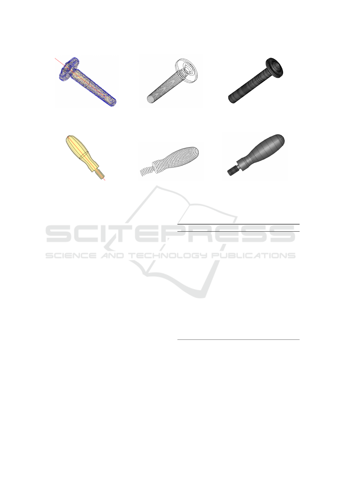
(a) Input point cloud (blue), re-
constructed mesh (yellow), principal
axis (red) and principal 3D profiles
(black).
(b) Principal 3D profiles (cross sec-
tions) extracted along the principal
axis.
(c) Output 3D model using SA-
LOME.
(d) Input mesh (yellow), principal
axis (red) and principal 3D profiles
(black).
(e) Principal 3D profiles (cross sec-
tions) extracted along the principal
axis.
(f) Output 3D model using SALOME.
Figure 2: Top row: from a 3D point cloud of a screw to 3D CAD model. Bottom row: from a 3D mesh of door handle to a
3D CAD model.
construction shall avoid incorporating user/company
dependent content. Hence, given an input 3D scan
(point cloud or mesh), the algorithm extracts ref-
erence sketch planes required to produce a feature-
based CAD model (i.e. a model produced by apply-
ing a sequence of operations like revolution, extrusion
and sweep). The need for constrained fitting is re-
laxed, hence providing explicit geometric constraints
is relaxed too. The geometric constrains are gener-
ally related to a set of predefined parameters that de-
fine generated surfaces. Such solutions make heavy
assumptions on the knowledge of each segmented re-
gion/part thanks to the classification step of the input
segments.
The proposed algorithm is general enough to pro-
vide 2D/3D contours and the main direction axes re-
quired for standard modeling operations (CAD fea-
tures) that together provide a meaningful design in-
tent bases for the designer to further create the
model. This representation (main axis and mean-
ingful 2D/3D profiles) in essence covers basic geo-
metric primitives (planes, spheres, cylinders, cones
and cuboids) as they can be directly generated us-
ing a rotation/directional extracted axis and a generat-
ing polyline (an extracted 2D/3D profile). Moreover,
many free-form shapes can be well reconstructed by
applying standard CAD modeling operations like rev-
olution, extrusion and sweep using a 2D/3D profile
and a rotational/directional axis or path.
Algorithm 1: Sketch planes extraction algorithm.
1. Input: 3D mesh (if a point cloud then recon-
struct a surface mesh using any standard algo-
rithm (Berger et al., 2017))
2. Extract the principle axes of the input object us-
ing principle component analysis (Botsch et al.,
2011)
3. Extract the sketch planes parallel to each of
the principle axes by means of mesh slic-
ing (Botsch et al., 2011)
4. Extract the sketch planes across a selected prin-
ciple axis (the main axis by default) by means
of mesh slicing
5. Save extracted principle axes and sketch planes
represented as polylines
The benefits of the proposed approach can be
seen in: a) being able to handle complete objects or
segmented parts rather than being applicable to seg-
mented regions only as in constrained primitive fit-
ting based approaches, b) no need for a large number
of prior scans and their CAD models as in learning-
based approaches c) having no obligation to have a
priori knowledge about the input scan, hence, not
forcing certain geometric constraints, d) geometric
constraints are implicitly imposed thanks to the sketch
extraction process which is done either parallel (as
Towards Automatic CAD Modeling from 3D Scan Sketch based Representation
395
in 1 - 3) or perpendicular (as in 1 - 4) to the princi-
ple axes and e) sketches representation as polylines in
ASCII format is supported by any CAD engine. The
proposed approach is validated by (semi) automating
the modeling process applied to the extracted inter-
mediate representation as explained in Algorithm 2 in
Section 4.
4 AUTOMATED MODELING AND
DISCUSSION
The proposed sketch extraction approach to create an
intermediate representation is tested on PartNet (Mo
et al., 2019), TraceParts (TraceParts S.A.S., 2019) and
implemented using Trimesh (Trimesh, 2019) and vtk-
plotter (Musy et al., 2019). It is validated by writing
generic automation Python scripts in SALOME 9.3.0
CAD modeling platform (Ribes and Caremoli, 2007)
to construct the corresponding CAD models of the in-
put scans given the intermediate representation only.
Figure 2a and Figure 2d show an input 3D point
cloud and a mesh respectively with the principal axis
and 3D principal profiles overlaid on them. The au-
tomatically extracted cross sections are shown in Fig-
ure 2b and Figure 2e and the automatically produced
models are shown in Figure 2c and Figure 2f. A more
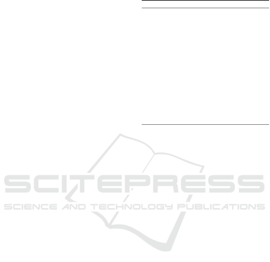
complex input mesh (a Faucet) is shown in Figure 3a
and its extracted principal profiles in Figure 3b, its
extracted cross sections through principal axes in Fig-
ure 3c and the semi-automatically produced model in
Figure 3d.
The automated CAD modeling scripts load the
ASCII files and produce revolution and generalized
sweep surfaces. Please note that automated extrusion
scripts can be easily similarly produced. These scripts
scan the input files for the principle axes, the principle
sketches and the sketches extracted across the main
principle axis. The (semi) automated modeling pro-
cess is explained in Algorithm 2.
The proposed modeling algorithm covers 1) rev-
olutions which are very common and fully rep-
resent the objects in many cases, 2) generalized
sweep through directed cross sections (along an auto-
generated path) which can reproduce the output of
one or more extrusion, revolution and sweep opera-
tions. It is straightforward to write a similar script
dedicated to extrusion. Given the output of the auto-
mated modeling script, the designer may intervene to
check the produced models and keep the most rele-
vant one(s) for further modification.
The sketch based representation would enable a
broader representation of objects which are not di-
rectly interpreted as geometric primitives. It supports
Algorithm 2: Automated modeling algorithm.
1. load the ASCII formatted files in the CAD en-
vironment
2. Apply revolutions corresponding to the princi-
pal profiles around their parallel axes in Algo-
rithm 1 - 3
3. Apply a generalized sweep on the sketch planes
extracted through the (default) main principal
axis in Algorithm 1 - 4
4. The sweep path is automatically constructed by
computing the 3D path through the 3D sketches
5. The designer may interactively:
(a) keep the generated features of interest
(b) change the default principal axes for revolu-
tion and sweeping
the generalization of the CAD modeling process elim-
inating the complexity of detecting geometric prim-
itives and computing their intersections to construct
accurate boundary representation.
The main limitation is that the current approach
is not fully automatic in some cases where the de-
signer may interfere to reject one or more extracted
features like the model shown in Figure 3d. The
top part is generated by an automated generalized
sweep while the bottom part is generated with auto-
mated revolutions. Another limitation is that fine de-
tails are not considered in this work yet. The out-
put shown of a revolved input screw in Figure 2c
has its internal head hole circular rather than being
shaped with sharp internal edges as its original form
in Figure 2a. Although the model automatically gen-
erated in Figure 2f faithfully represent its input mesh
in Figure 2d, the automatically generated cross sec-
tions in the lower part do not fit well the handle thread.
It needs more dense sections extracted, however the
dense versus sparse sections extraction needs to be
fully automated. Currently, an equidistant number of
sections is extracted relative to the input scan height.
Future work, will consider fully automating cross sec-
tions density, sketches filtering and mixed modeling
to decide on the most relevant operation given the in-
put sketches and axes.
5 CONCLUSIONS
This paper proposes a novel approach to convert an
input 3D scan to a CAD model. The core idea is to
extract reference sketches which act as an interme-
diate representation between the input scan and the
GRAPP 2020 - 15th International Conference on Computer Graphics Theory and Applications
396
(a) Input 3D mesh. (b) Principal 3D profiles (sketch planes).
(c) Principal 3D profiles (cross sections) extracted along
the principal axis.
(d) Output 3D model using SALOME.
Figure 3: Complex Faucet example: from 3D mesh to 3D CAD model.
final model. They keep, to certain extent, the orig-
inal design intent. This eases the designer interac-
tion with the automatically generated models wher-
ever required. The automation of the modeling step
is straight forward using these sketches. The bene-
fits of the proposed approach can be seen in relax-
ing the need to extract specific geometric primitives
which remove the complexity of carefully designing
well constrained optimization problems. There is no
need to have a priori knowledge of every single seg-
mented region or provide a large database of scans
and CADs for learning. The proposed approach im-
plicitly imposes geometric constraints like parallelism
on subsequent extracted sections and perpendicularity
constraints between the sweep axis and base sketch
plane(s). The intermediate sketches are saved in
ASCII format which naturally supports any available
CAD software packages. The proposed method is val-
idated by automating the modeling process for simple
and complex objects.
REFERENCES
Avetisyan, A., Dahnert, M., Dai, A., Savva, M., Chang,
A. X., and Nießner, M. (2019). Scan2cad: Learning
CAD model alignment in RGB-D scans. In IEEE Con-
ference on Computer Vision and Pattern Recognition,
CVPR, USA, June 16-20, pages 2614–2623.
Barh, D. and Azevedo, V. (2018). Chapter 5 - reverse en-
gineering and its applications. In Omics Technolo-
gies and Bio-Engineering, pages 95 – 110. Academic
Press.
Benk
¨
o, P., K
´
os, G., V
´
arady, T., Andor, L., and Martin, R. R.
(2002). Constrained fitting in reverse engineering.
Computer Aided Geometric Design, 19(3):173–205.
Berger, M., Tagliasacchi, A., Seversky, L. M., Alliez, P.,
Guennebaud, G., Levine, J. A., Sharf, A., and Silva,
C. T. (2017). A survey of surface reconstruction from
point clouds. Comput. Graph. Forum, 36(1):301–329.
Botsch, M., Kobbelt, L., Pauly, M., Alliez, P., and Levy,
B. (2011). Polygon mesh processing relations. Book,
CRC Press, 1st Edition.
Brachmann, E., Krull, A., Nowozin, S., Shotton, J., Michel,
F., Gumhold, S., and Rother, C. (2017). DSAC - dif-
ferentiable RANSAC for camera localization. In 2017
Towards Automatic CAD Modeling from 3D Scan Sketch based Representation
397

IEEE Conference on Computer Vision and Pattern
Recognition, CVPR, USA, July 21-26, pages 2492–
2500.
Buonamici, F. and Carfagni, M. (2016). Reverse engineer-
ing of mechanical parts: A brief overview of existing
approaches and possible new strategies. International
Design Engineering Technical Conferences and Com-
puters and Information in Engineering Conference.
Chum, O. and Matas, J. (2005). Matching with PROSAC -
progressive sample consensus. In 2005 IEEE Com-
puter Society Conference on Computer Vision and
Pattern Recognition CVPR, 20-26 June, USA, pages
220–226.
Dahnert, M., Dai, A., Guibas, L., and Nießner, M. (2019).
Joint embedding of 3d scan and cad objects.
Du, T., Inala, J. P., Pu, Y., Spielberg, A., Schulz, A., Rus,
D., Solar-Lezama, A., and Matusik, W. (2018). In-
versecsg: automatic conversion of 3d models to CSG
trees. ACM Trans. Graph., 37(6):213:1–213:16.
Fischler, M. A. and Bolles, R. C. (1981). Random sample
consensus: A paradigm for model fitting with appli-
cations to image analysis and automated cartography.
Commun. ACM, 24(6):381–395.
Gauthier, S., Puech, W., B
´
eni
`
ere, R., and Subsol, G. (2019).
Cad-driven pattern recognition in reverse engineered
models. In Proceedings of the 14th International Joint
Conference on Computer Vision, Imaging and Com-
puter Graphics Theory and Applications, VISIGRAPP
2019, Volume 1: GRAPP, Prague, Czech Republic,
February 25-27, 2019., pages 244–254.
Jia, P. (2017). Fitting a parametric model to a cloud of
points via optimization methods.
Kaiser, A., Zepeda, J. A. Y., and Boubekeur, T. (2019). A
survey of simple geometric primitives detection meth-
ods for captured 3d data. Computer Graphics Forum,
38(1):167–196.
Kang, Z. and Li, Z. (2015). Primitive fitting based on the
efficient multibaysac algorithm. PLOS ONE, 10(3):1–
21.
Kov
´
acs, I., V
´
arady, T., and Salvi, P. (2015). Applying ge-
ometric constraints for perfecting CAD models in re-
verse engineering. Graphical Models, 82:44–57.
Li, L., Sung, M., Dubrovina, A., Yi, L., and Guibas, L. J.
(2019). Supervised fitting of geometric primitives to
3d point clouds. In IEEE Conference on Computer
Vision and Pattern Recognition, CVPR, USA, June 16-
20, pages 2652–2660.
Li, Y., Wu, X., Chrysanthou, Y., Sharf, A., Cohen-Or, D.,
and Mitra, N. J. (2011). Globfit: consistently fit-
ting primitives by discovering global relations. ACM
Trans. Graph., 30(4):52.
Mo, K., Zhu, S., Chang, A. X., Yi, L., Tripathi, S., Guibas,
L. J., and Su, H. (2019). PartNet: A large-scale bench-
mark for fine-grained and hierarchical part-level 3D
object understanding. In The IEEE Conference on
Computer Vision and Pattern Recognition (CVPR).
Musy, M., Dalmasso, G., Sharpe, J., and Sime, N. (2019).
vtkplotter: plotting in fenics with python. In FEn-
iCS’2019 Conference.
Patil, A. K., Holi, P., Lee, S. K., and Chai, Y. H. (2017). An
adaptive approach for the reconstruction and modeling
of as-built 3d pipelines from point clouds. Automation
in Construction, 75:65 – 78.
Ranftl, R. and Koltun, V. (2018). Deep fundamental matrix
estimation. In Computer Vision - ECCV 2018 - 15th
European Conference, Munich, Germany, September
8-14, 2018, Proceedings, Part I, pages 292–309.
Ribes, A. and Caremoli, C. (2007). Salom
´
e platform com-
ponent model for numerical simulation. COMPSAC
07: Proceeding of the 31st Annual International Com-
puter Software and Applications Conference, pages
553–564.
Schnabel, R., Wahl, R., and Klein, R. (2007). Efficient
ransac for point-cloud shape detection. Computer
Graphics Forum, 26(2):214–226.
Sharma, G., Goyal, R., Liu, D., Kalogerakis, E., and Maji,
S. (2018). Csgnet: Neural shape parser for con-
structive solid geometry. In 2018 IEEE Conference
on Computer Vision and Pattern Recognition, CVPR,
USA, June 18-22, pages 5515–5523.
TraceParts S.A.S. (2019). TraceParts.
Trimesh (2019). [Computer software]. Retrieved from
https://github.com/mikedh/trimesh.
Tulsiani, S., Su, H., Guibas, L. J., Efros, A. A., and Ma-
lik, J. (2017). Learning shape abstractions by assem-
bling volumetric primitives. In 2017 IEEE Conference
on Computer Vision and Pattern Recognition, CVPR,
USA, July 21-26, pages 1466–1474.
V
´
arady, T., Martin, R. R., and Cox, J. (1997). Reverse
engineering of geometric models - an introduction.
Computer-Aided Design, 29(4):255–268.
Werghi, N., Fisher, R. B., Robertson, C., and Ashbrook, A.
(1999). Object reconstruction by incorporating geo-
metric constraints in reverse engineering. Computer-
Aided Design, 31(6):363–399.
Wu, Q., Xu, K., and Wang, J. (2018). Constructing 3d CSG
models from 3d raw point clouds. Comput. Graph.
Forum, 37(5):221–232.
Yi, C., Zhang, Y., Wu, Q., Xu, Y., Remil, O., Wei, M., and
Wang, J. (2017). Urban building reconstruction from
raw lidar point data. Computer-Aided Design, 93:1–
14.
Zou, C., Yumer, E., Yang, J., Ceylan, D., and Hoiem, D.
(2017). 3d-prnn: Generating shape primitives with re-
current neural networks. In IEEE International Con-
ference on Computer Vision, ICCV 2017, Venice, Italy,
October 22-29, 2017, pages 900–909.
GRAPP 2020 - 15th International Conference on Computer Graphics Theory and Applications
398
