
3D Augmented Reality Tangible User Interface using Commodity
Hardware
Dimitris Chamzas
a
and Konstantinos Moustakas
b
Department of Electrical and Computer Engineering, University of Patras, Rio Campus, Patras 26504, Greece
Keywords:
Augmented Reality Environments, 3D Tracking, 3D Registration, Convex Polygon Corner Detection.
Abstract:
During the last years, the emerging field of Augmented & Virtual Reality (AR-VR) has seen tremendous growth.
An interface that has also become very popular for the AR systems is the tangible interface or passive-haptic
interface. Specifically, an interface where users can manipulate digital information with input devices that are
physical objects. This work presents a low cost Augmented Reality system with a tangible interface that offers
interaction between the real and the virtual world. The system estimates in real-time the 3D position of a small
colored ball (input device), it maps it to the 3D virtual world and then uses it to control the AR application
that runs in a mobile device. Using the 3D position of our “input” device, it allows us to implement more
complicated interactivity compared to a 2D input device. Finally, we present a simple, fast and robust algorithm
that can estimate the corners of a convex quadrangle. The proposed algorithm is suitable for the fast registration
of markers and significantly improves performance compared to the state of the art.
1 INTRODUCTION
Augmented & Virtual Reality (AR-VR) systems and
applications have seen massive development and have
been studied extensively over the last few decades
(Azuma, 1997; Billinghurst et al., 2015; Avouris et al.,
2015). Virtual reality (VR) is an artificial 3D environ-
ment generated with software. Users are immersed in
this 3D world, and they tend to accept it as a real envi-
ronment. On the other hand, Augmented Reality (AR)
is a technology that blends digital content into our real
world. Thus, AR combines real and virtual imagery,
is interactive in real-time, and registers the virtual im-
agery with the real world. AR & VR systems require
specialized hardware and most of the time they are
quite expensive.
In contrast with Virtual Reality, where the user is
completely immersed in a virtual environment, AR al-
lows the user to interact with the AR digital world
and manipulate the virtual content via special input de-
vices. Three-dimensional visualization would be ide-
ally accompanied by 3D interaction, therefore 3D in-
put devices are highly desirable (Reitmayr et al., 2005).
To reduce the complexity, the input device we choose,
is a simple, colored ball at the end of a stick with three
a
https://orcid.org/0000-0002-4375-5281
b
https://orcid.org/0000-0001-7617-227X
degrees of freedom (DOF). We will refer to it as the
AR-POINTER.
Building an AR system we have to decide on how
to implement its three basic functions. Display, where
we have to combine images from the real and virtual
world, Tracking, where we have to find the position
of the user’s viewpoint in the real world and register
its view in the 3D virtual world and a User Interface
(Input-Interaction), where a computer responds in real-
time to the user input and generates interactive graph-
ics in the digital world. With the advances in mobile
device technology, handheld computing devices are
becoming powerful enough to support the functional-
ities of an AR System. Google’s ARcore platform is
such an example. Considering that we want to build a
low-cost AR system with a 3D tangible input interface,
we choose a mobile phone, running Unity and Vufo-
ria, to implement the AR Video-based Display and
the Traking modules while the tangible User Interface
is implemented in a ”custom-made” device running
Open Source software.
The contributions of this paper are threefold. First,
we describe the development of a DIY (Do It Yourself)
low-cost AR-VR working prototype system with a 3D
tangible user interface that can be used as a test-bed
to examine a variety of problems related to 3D inter-
action in VR or AR environments. Second, the usage
of the real 3D position of the tangible input device
384
Chamzas, D. and Moustakas, K.
3D Augmented Reality Tangible User Interface using Commodity Hardware.
DOI: 10.5220/0009173303840391
In Proceedings of the 15th International Joint Conference on Computer Vision, Imaging and Computer Graphics Theory and Applications (VISIGRAPP 2020) - Volume 1: GRAPP, pages
384-391
ISBN: 978-989-758-402-2; ISSN: 2184-4321
Copyright
c
2022 by SCITEPRESS – Science and Technology Publications, Lda. All rights reserved
obtained via an adaptive color and distance camera
registration algorithm, offers a powerful and flexible
environment for interactivity with the digital world of
AR-VR. Third, we present cMinMax, a new algorithm
that can estimate the corners of a convex polygon. This
algorithm is suitable for the fast registration of mark-
ers in augmented reality systems and in applications
where real-time feature detector is necessary. cMin-
Max is faster, approximately by a factor of 10, and
more robust compared to the widely used Harris Cor-
ner Detection algorithm.
2 RELATED WORK
During the last two decades AR research and develop-
ment have seen rapid growth and as more advanced
hardware and software becomes available, many AR
systems with quite different interfaces are moving out
of the laboratories to consumer products. Concern-
ing the interactivity of an AR system, it appears that
users prefer for 3D object manipulation to use the
so-called Tangible User Interface (TUI) (Billinghurst
et al., 2008; Ishii et al., 2008), Thus for the Interactiv-
ity interface, we follow the Tangible Augmented Re-
ality approach, a concept initially proposed by T. Ishii
(Ishii and Ullmer, 1997). This approach offers a very
intuitive way to interact with the digital content and it
is very powerful since physical objects have familiar
properties and physical constraints, therefore they are
easier to use as input devices (Ishii et al., 2008; Shaer
et al., 2010). Besan
c¸
on et al. compared the mouse-
keyboard, tactile, and tangible input for AR systems
with 3D manipulation (Besan
c¸
on et al., 2017). They
found that the three input modalities achieve the same
accuracy, however, tangible input devices are more
preferable and faster. To use physical objects as in-
put devices for interaction requires accurate tracking
of the objects, and for this purpose, many Tangible
AR applications use computer vision-based tracking
software.
An AR system with 3D tangible interactivity and
optical tracking is described in (Martens et al., 2004),
where 3D input devices tagged with infrared-reflecting
markers are optically tracked by well-calibrated in-
frared stereo cameras. Following this approach, we
attempted to build an AR system with a 3D tangible
input interface using a multicamera smartphone. Un-
fortunately, it did not succeed because neither Android
or iOS SDKs were offering adequate support for multi-
ple cameras nor the smartphone we used was allowing
full access to their multiple cameras images to esti-
mate the distance of the input device using binocular
stereo vision. In addition, the fact that the cameras
were too close and not identical it was one more prob-
lem.
With the recent technical advances and commer-
cialization of depth cameras (e.g. Microsoft Kinect)
more accurate tracking of moving physical objects be-
came available for VR-AR applications. Such an ap-
proach is described in (Hernandez-Lopez et al., 2012)
where the 3D position of a moving object is estimated
utilizing the images of an RGB camera and a depth
sensor. Taking into consideration that depth cameras
start to appear in mobile devices, we decided to follow
a similar approach and instead of using stereo vision
to estimate the distance of the 3D input device we use
one RGB and one depth camera.
A different approach is used in (Teng and Peng,
2017), where a user with a mobile device and two AR
”markers” can perform a 3D modeling task using a tan-
gible interface. Markers are realized as image targets.
The first image target is applied to create the virtual
modeling environment and the second image target is
used to create a virtual pen. Using Vufuria’s platform
they estimate its position in the 3D world and interact
accordingly. However, this input device, a stick with
an image target attached to its end, is difficult to use,
it is not accurate and it is not a real 3D input device
since the system knows its 3D position in the virtual
world but not in the real one.
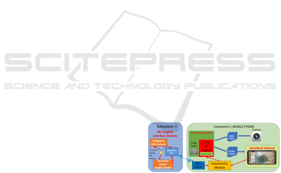
3 SYSTEM ARCHITECTURE
Our system architecture implements the three mod-
ules of an AR-system, Tracking, Display and User In-
terface, in two separate subsystems that communicate
Figure 1: System Architecture.
via WiFi (Figure 1).
The
First Subsystem
implements Tracking and
Display, and it contains an Android mobile phone (Xi-
aomi Red-mi Note 6 pro)
(Figure 2) running a 3D Unity Engine with Vuforia
where by utilizing an ”image target” the front camera
projects the augmented environment on our screen.
The
Second Subsystem
implements the 3D tan-
gible AR User’s interface (TUI) and it consists of a
Raspberry Pi 4 with an RGB Raspberry Camera and
3D Augmented Reality Tangible User Interface using Commodity Hardware
385
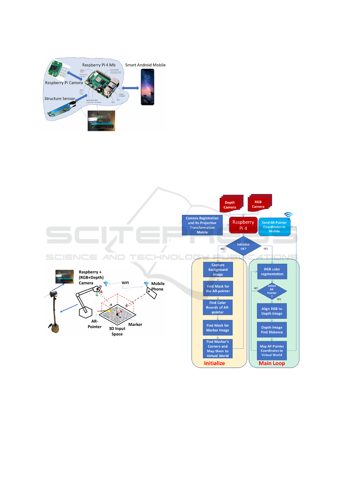
Figure 2: Hardware.
a depth camera (Structure Sensor) housed in a home-
made 3D-printed case. The Structure Sensor projects
an infrared pattern which is reflected from the differ-
ent objects in the scene. Its IR camera captures these
reflections and computes the distance to every object
in the scene while at the same time the Raspberry cam-
era captures the RGB image. All the processing power
in the second subsystem is done in the Raspberry Pi 4.
It uses python as well as the OpenCV library for image
processing, Matlab was also used as a tool for testing
main algorithms before their final implementation.
4 IMPLEMENTATION
An illustrative example of the setup of our system in
the real world is shown in Figure 3.
Figure 3: The AR system.
As it was described in section 3 our system is com-
posed of two different subsystems. The first subsys-
tem, the mobile phone, is responsible for the visual-
ization of the Augmented Reality environment. The
virtual objects are overlaid on a predefined target im-
age printed on an A4 paper. Thus the mobile phone
is responsible for graphics rendering, tracking, marker
calibration, and registration as well as for merging vir-
tual images with views of the real world. The second
subsystem is attached to a ”desk lamb arm”, and faces
the target image. This system is responsible to align
the images from the two cameras, locate the 3D co-
ordinates of a predefined physical object(yellow ball),
namely the AR-POINTER, transform its XYZ coordi-
nates to Unity coordinates and send them to mobile via
WiFi. The physical pointer, which has a unique color,
is localized via an adaptive color and distance camera
registration algorithm. The physical AR-POINTER has
its virtual counterpart in the AR world, a virtual red
ball, which represents the real 3D input device. Thus,
by moving the real AR-POINTER in the real 3D world,
we move the virtual AR-POINTER in the virtual world,
interacting with other virtual objects of the application.
This is a tangible interface, which gives to the user the
perception of a real object interacting with the virtual
world. The subsystems use the marker as the common
fixed frame and communicate through wi-fi. Figure 1
shows the building blocks of our subsystems and Fig-
ure 4 displays the flowchart of the processes running
in the second subsystem.
Figure 4: Flow Chart of Processes Running in Raspberry.
4.1 Camera Registration
Since the two different cameras (RGB, Depth) are con-
nected to the Raspberry and the position of each other
is different in space, the images taken by the two cam-
GRAPP 2020 - 15th International Conference on Computer Graphics Theory and Applications
386
eras are slightly misaligned. To correct this, we find
a homographic transformation that compensates dif-
ferences in the geometric location of the two cameras.
Using a plug-in of matlab called registration-Estimator
we select SIFT algorithm to find the matching points
and to return affine transformation.
4.2 Initialization
At initialization, masks that filter the background, the
color bounds of the physical AR-POINTER and the real
to virtual world coordinates mappings are calculated.
4.2.1 Find Mask
During initialization, the image target, and the AR-
POINTER) need to be separated from their background.
To this end, two binary masks are created to filter out
the background with the following method:
1. Capture background image.
2.
Place object (Marker or AR-POINTER) and capture
the second image.
3. Subtract images in absolute value.
4. Apply adaptive threshold (Otsu) & blur filter.
5.
Edge detection ( Canny algorithm) & fill contours.
6.
Create a binary image (mask) by selecting the con-
tour with the largest area.
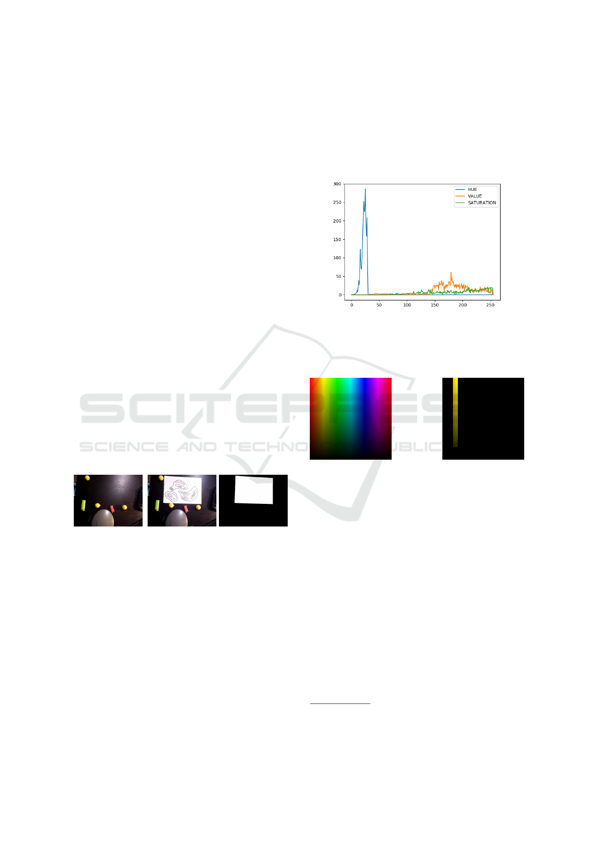
In Figure 5 we see the inputs to create the mask
(steps 1 and 2) and the obtained mask (step 6)
Figure 5: The background without and with the object and
the mask.
4.2.2 Find Color Bounds
Variations in the room illumination can make the same
object appear with different RGB values. To address
this, the following method was developed that detects
the color bounds of the AR-POINTER under the light
conditions of the room. The decided to use the HSV
representation since the colors are separable in the
HUE axis whereas in RGB all the three axes are
needed.
1. Find mask of AR-POINTER (see 4.2.1).
2. Isolate pointer from image.
3. Convert RGB image to HSV.
4.
Calculate histogram & find max value of Hue
HSV.
5. Create new bounds ±15 at HSV.
In Figure 6 the histogram of the example in Fig-
ure 11 is shown. It can be derived (step 4) that the
AR-POINTER is near Hue=20
1
.
Figure 6: HSV Histogram.
By applying the derived bounds
(5 ≤ HUE ≤ 35)
on the RGB color spectrum only the yellow spectrum
is kept (Figure 7).
Figure 7: Derived bounds isolate the yellow spectrum.
Identifying the color bounds makes our system ro-
bust to light variations and enables the use of multiple
differently colored AR-POINTER objects.
4.2.3 AR Registration
To allow the interaction with the digital world via the
motion of the AR-POINTER we need to map its real-
world 3D coordinates
(x
r
,y
r
,z
r
)
to the digital world
coordinates
(x
v
,y
v
,z
v
)
. To calculate this mapping the
common object of reference is the Image Target as
shown in Figure 3.
Since the image frames are almost vertically
aligned we can approximate the relation between the z
coordinates (distance) with a scalar factor
ρ
z
≈ ρ
z
(x,y)
which is proportional to the size of the image (see
also 4.4.3). This can be derived to obtain
z
v
= ρ
z
z
r
.
To map the
(x
r
,y
r
)
coordinates we need to find a pro-
jective transformation matrix (
T
RV
) to account mainly
1
8bit pixel value, to obtain real HUE values multiply by
2, since in OpenCV max HUE is 180
3D Augmented Reality Tangible User Interface using Commodity Hardware
387
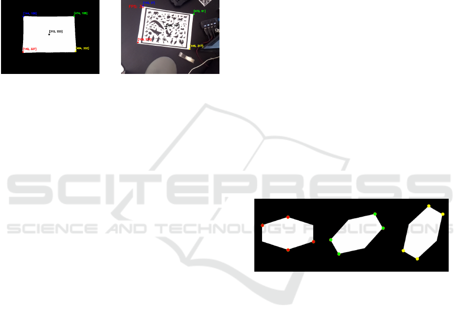
for translation and rotation offset. To calculate
T
RV
,
we need at least four points. To this end, we used the
four corners of the image target mask, and map them
to the Unity four corners of the marker (Figure 13).
Unity has constant coordinates where each corner of
the marker is located at
(±0.5,±0.75)
, So first we will
find the corners of the marker running the appropriate
software in Raspberry and then we will find the trans-
formation matrix that moves those points to the Unity
virtual space.
Figure 8: Corner Detection.
To find the corners of the marker we first create
the mask of the marker as described in 4.2.1 and then
find its corners. Initially, we used the Harris Corner
Detection Algorithm from OpenCV (OpenCV, 2019),
but later on, we developed another simpler and faster
algorithm, the cMinMax (see subsection 4.3). After
we found the four corners (see Figure 8) we add a fifth
point, the center of gravity of the marker for better re-
sults. We calculate the center of gravity as the average
of X & Y coordinates for all the pixels in the mask.
Now, we use the two sets of points (Real World
points, Unity points) and with the help of OpenCV,
we get the projective transformation matrix. This pro-
cess needs to be done only once at the start of the
program and not in the main loop gaining in compu-
tational power. The result of matching the real world
with the virtual one is that we can now project the
virtual AR-POINTER at the same position where the
real AR-POINTER is on the smartphone screen, making
those 2 objects (real-yellow,virtual-red) to coincide.
4.3 cMinMax: A Fast Algorithm to
Detect the Corners in a Quadrangle
A common problem in image registration (see section
4.2.3) is to find the corners of an image. One of the
most popular algorithms to address this problem is the
Harris Corner Detection (Harris et al., 1988; OpenCV,
2019). However, most of the time the image is the
photo of a parallelogram, which is a convex quadran-
gle. To address this specific problem we have devel-
oped a specific algorithm, referred to as cMinMax,
to detect the four corners in a fast and reliable way.
The algorithm utilizes the fact that if we find the x-
coordinates of the pixels that belong to the mask, then
their maximum,
x
max
, is a corner’s coordinate. Simi-
larly for
x
min
,
y
min
and
y
max
. The proposed algorithm
is approximately 10 times faster and more robust than
the Harris Corner Detection Algorithm, but its appli-
cability is limited only to convex polygons.
The basic steps of the algorithm are:
1. Preprocessing:
Generate a bi-level version of the
image with the mask.
2.
Project the image on the vertical and horizontal
axis and find the
(x
min
,x
max
,y
min
,y
max
)
. These are
coordinates of four corners of the convex polygon.
3.
If
N
is the expected maximum number of angles,
then for
k = 1,..,int(N/2)−1
, rotate the image by
∆θ = k ∗ pi/N
and repeat the previous step. Iden-
tify the four additional corners, rotate the image
backward by
−∆θ
and find their position in the
original image.
4.
In the end, we have found
2N
points which is
greater than the number of expected polygon cor-
ners. Hence, there are more than one pixels around
each corner. The centroids of these bunches are the
estimated corners of the convex polygon.
5.
If the number of detected corners is less than N, re-
peat the previous three steps by rotating the image
with ∆θ = (k ∗ pi/N) − pi/2N
Figure 9: Detected corners in a hexagon for M=3.
In Figure 9 we apply the algorithm in a hexagon
and we find all the corners with three rotations.
4.4 AR-POINTER Detection (Main
Loop)
In the main loop the 3D position of the physical AR-
POINTER is continuously estimated and transmitted to
the mobile phone.
4.4.1 RGB Color Segmentation
The X & Y coordinates will be acquired from the
RGB image. The AR-POINTER that we used is a ”3D-
printed” yellow ball. Our segmentation is based on
color, thus we can use any real object with the limita-
tion to have a different color from the background.
Since we have our HSV color bounds (see section
GRAPP 2020 - 15th International Conference on Computer Graphics Theory and Applications
388
4.2.2) the detection of the object used as the AR-
POINTER is straightforward.
1. Convert RGB input image to type HSV.
2.
Keep pixel values only within preset HSV color
bounds (section 4.2.2).
3. Edge detection ( Canny algorithm).
4.
Find and save the outlined rectangle of contour
with maximum area.
Filtering the RGB image with the color bounds
results to the first image of Figure 10. Then, we create
a rectangle that contains the AR-POINTER and use its
center as the coordinates of it (see the second image
of Figure 10).
Figure 10: Color detection.
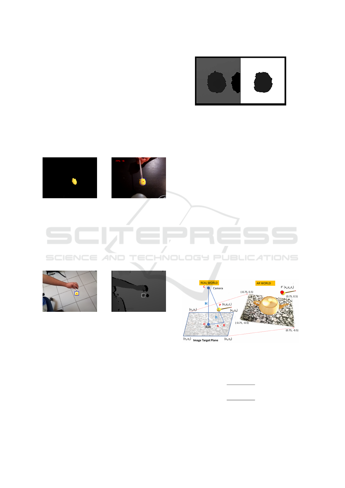
4.4.2 Depth Estimation
The 3D coordinates of the AR-POINTER will be ac-
quired from the depth image. Knowing where the AR-
POINTER is located in the RGB image from the Color
Segmentation, and since the images are aligned, we
crop a small rectangle from the depth image that con-
tains the area of the AR-POINTER (Figure 11).
Figure 11: AR-POINTER 3D detection.
This rectangle contains all the depth information
we need and since it is a small part of the image it
reduces also the computational cost. In this rectangle
there are 3 different depth information (see Figure 12):
1.
Depth information of the AR-POINTER (pixel val-
ues: 1000-8000).
2.
Depth information of background (pixel values:
7000-8000).
3.
Depth information for the area which is created
by the AR-POINTER that blocks the IR emission
creating a shadow of the object (pixel value: 0 ).
Given the fact that the background always corresponds
to the maximum value, we do the following on.
Figure 12: Pre-process of the depth image.
1.
We calculate the average of non-zero elements of
rectangle image, (Figure 12 first image).
2.
Set to zero all pixels with values
> 10%
of average,
(Figure 12 second image).
3.
Recalculate average of non-zero elements and use
it as the final depth value for the AR-POINTER.
With this approach, we get stable values for small
changes of AR-POINTER, fast results and precision be-
low 1 cm.
4.4.3 Map AR-POINTER Coordinates to Virtual
Word
At this point we know the distance of the AR-POINTER
from the Image Target plane (see subsubsection 4.4.2),
as well its position on the RGB image (see subsubsec-
tion 4.4.1). Since the AR-POINTER is not in the Image
Target plane, the position of the AR-POINTER on the
RGB image is the B point and not the A (see Fig-
ure 13 ) as it should be. We know
h
and
H
, therefore
the correction vector
−−→
(AB)
is given from the relation
−−→
(AB) =
−−→
(OA) ∗ h/H.
Figure 13: Depth Correction.
Therefore the coordinates of the AR-POINTER in
the real word are
x
rA
= x
rB
∗
(OB) − (AB)
(OB)
y
rA
= y
rB
∗
(OB) − (AB)
(OB)
, z
r
= h
and the coordinates in the virtual world are
3D Augmented Reality Tangible User Interface using Commodity Hardware
389
"
x
vA
y
vA
1
#
= T
RV
"
x
rA
y
rA
1
#
, z
v
= ρ
z
∗ z
r
where T
RV
and ρ
z
were define in subsubsection 4.2.3.
4.5 AR Engine
The final AR engine is a marker-based AR-system
with AR video display. It runs exclusively in the mo-
bile phone, Figure 1, and is based on the 3D Unity
platform. It executes the following steps.
1. Capture images with the mobile’s built in camera.
2.
Detects the image target(marker) in the real world.
3.
Displays the virtual environment on top of the im-
age target and the virtual AR-POINTER in the mo-
bile screen.
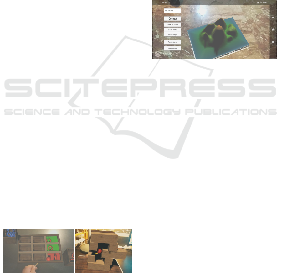
5 APPLICATIONS AND
EXPERIMENTS
Using the tangible user interface three AR application
were developed. The 3D position of the AR-POINTER
is used to interact with the virtual world where it ap-
pears as a red ball.
5.1 The Tic-Tac-Toe Game Application
A Tic-Tac-Toe game was implemented on top of our
system to demonstrate its interactivity. In Figure 14,
where a screenshot of the application is shown, the
option of selecting and deselecting an object (such as
X or O) into the Virtual world is highlighted. It can be
seen that our system offers the simple but important
commands of that every AR application does require.
5.2 The Jenga Game Application
Additionally, a Jenga game was implemented to
demonstrate the precision and stability of our system.
This application can be seen in (Figure 15. Since this
game demands such features in real life, its implemen-
tation in our system, showcases the system’s practical-
ity and functionality.
Figure 14: Tic-Tac-Toe Game.
Figure 15: Jenga Game.
5.3 The 3D Contour Map Application
The last game that was designed is the creation of 3D
height maps (Figure 16) using our tangible interface.
In this application we are able to create mountains
and valleys, building our terrain. Also in this particu-
lar application, we have the ability to create and then
process 3D terrains from real height maps after an im-
age process running at raspberry creating the 3d mesh.
This process is based on the previous work of (Pana-
giotopoulos et al., 2017). In this particular application,
we are showing the advantages of having the 3D coor-
dinates giving us the ability to set much more compli-
cates commands such as setting the height.
Figure 16: A screenshot from the Contour Map App.
A video clip with these applications is
available at https://www.youtube.com/watch?v=
OyU4GOLoXnA .
6 DISCUSSION & CONCLUSION
This work was a proof of concept that a marker-based
low-cost AR with 3D TUI running in real-time (25-30
fps) is feasible to implement and use it as a testbed for
identifying various problems and investigate possible
solutions. If we add one or more input devices with a
different color and/or different shape, then the current
implementation is scalable to co-located collaborative
AR, supporting two or more users. The knowledge in
real-time of the 3D position of the input device offers
a powerful and flexible environment for interactivity
with the digital world of AR.
Some advantages of the system are Fast 3D Reg-
istration Process, Fast Corner Detection Algorithm,
Depth Adaptive Camera Calibration, Data Fusion
from RGB and Depth Camera, Simple and Fast Image
segmentation, Real-Time Operation, Versatility, Open
Source Implementation and Hardware Compatibility.
6.1 Future Directions
Today, there is a lot of effort towards developing
high-quality AR systems with tangible user interfaces.
GRAPP 2020 - 15th International Conference on Computer Graphics Theory and Applications
390

Microsoft-Hololense
2
and Holo-Stylus
3
are just two
of them. However, all of them are build on special-
ized hardware and proprietary software and there are
expensive. On the other side, smartphones are contin-
uously evolving, adding more computer power, more
sensors, and high-quality display. Multi cameras and
depth sensors are some of their recent additions. There-
fore, we expect that it will be possible to implement
all the functionalities of an AR system just in a smart-
phone. In this case, computing power will be in de-
mand. We will need to develop new fast and efficient
algorithms. One way to achieve this is to make them
task-specific. cMinMax is such an example, where
we can find the corners of a marker (convex quad-
rangle) almost ten times faster than the commonly
used Harris Corner Detection algorithm. The fusion
of data obtained from different mobile sensors (multi-
ple RGB cameras, Depth Camera, Ultrasound sensor,
Three
-
axis gyroscope, Accelerometer, Proximity sen-
sor, e.t.c) to locate in real-time 3D objects in 3D space
and register them to the virtual world is another chal-
lenging task. A simple example is presented in subsub-
section 4.4.3, where we combine data from an RGB
and a Depth camera in order to find the 3D coordinates
of a small ball (approximated with a point) in space.
7 CONCLUSIONS
This paper has presented the implementation of an in-
expensive single-user realization of a system with a
3D tangible user interface build with off the selves
components. This system is easy to implement, it runs
in real-time and it is suitable to use as an experimental
AR testbed where we can try new concepts and meth-
ods. We did optimize its performance either by mov-
ing computational complexity out of the main loop
of operation or by using task-specific fast procedures.
cMinMax, a new algorithm for finding the corners of
a markers mask, is such an example, where we have
sacrifice generality in order to gain speed.
ACKNOWLEDGEMENTS
We would like to thank the members of the Visualiza-
tion and Virtual Reality Group of the Department of
Electrical and Computer Engineering of the Univer-
sity of Patras as well as the members the Multimedia
Research Lab of the Xanthi’s Division of the ”Athena”
2
https://www.microsoft.com/en-us/hololens
3
https://https://www.holo-stylus.com
Research and Innovation Center, for their comments
and advice during the preparation of this work.
REFERENCES
Avouris, N., Katsanos, C., Tselios, N., and Moustakas, K.
(2015). Introduction to human-computer interaction.
The Kallipos Repository.
Azuma, R. T. (1997). A survey of augmented reality. Pres-
ence: Teleoperators & Virtual Environments, 6(4):355–
385.
Besan
c¸
on, L., Issartel, P., Ammi, M., and Isenberg, T. (2017).
Mouse, tactile, and tangible input for 3d manipulation.
In Proceedings of the 2017 CHI Conference on Hu-
man Factors in Computing Systems, pages 4727–4740.
ACM.
Billinghurst, M., Clark, A., Lee, G., et al. (2015). A survey
of augmented reality. Foundations and Trends
®
in
Human–Computer Interaction, 8(2-3):73–272.
Billinghurst, M., Kato, H., and Poupyrev, I. (2008). Tangible
augmented reality. ACM SIGGRAPH ASIA, 7.
Harris, C. G., Stephens, M., et al. (1988). A combined corner
and edge detector. In Alvey vision conference, volume
15.50, pages 10–5244. Citeseer.
Hernandez-Lopez, J.-J., Quintanilla-Olvera, A.-L., L
´
opez-
Ram
´
ırez, J.-L., Rangel-Butanda, F.-J., Ibarra-Manzano,
M.-A., and Almanza-Ojeda, D.-L. (2012). Detecting
objects using color and depth segmentation with kinect
sensor. Procedia Technology, 3:196–204.
Ishii, H. et al. (2008). The tangible user interface and its
evolution. Communications of the ACM, 51(6):32.
Ishii, H. and Ullmer, B. (1997). Tangible bits: towards seam-
less interfaces between people, bits and atoms. In Pro-
ceedings of the ACM SIGCHI Conference on Human
factors in computing systems, pages 234–241. ACM.
Martens, J.-B., Qi, W., Aliakseyeu, D., Kok, A. J., and van
Liere, R. (2004). Experiencing 3d interactions in vir-
tual reality and augmented reality. In Proceedings of
the 2nd European Union symposium on Ambient intel-
ligence, pages 25–28. ACM.
OpenCV (2019). Harris corner detection. https://docs.
opencv.org/master/d4/d7d/tutorial harris detector.
html.
Panagiotopoulos, T., Arvanitis, G., Moustakas, K., and Fako-
takis, N. (2017). Generation and authoring of aug-
mented reality terrains through real-time analysis of
map images. In Scandinavian Conference on Image
Analysis, pages 480–491. Springer.
Reitmayr, G., Chiu, C., Kusternig, A., Kusternig, M., and
Witzmann, H. (2005). iorb-unifying command and 3d
input for mobile augmented reality. In Proc. IEEE VR
Workshop on New Directions in 3D User Interfaces,
pages 7–10.
Shaer, O., Hornecker, E., et al. (2010). Tangible user in-
terfaces: past, present, and future directions. Founda-
tions and Trends
®
in Human–Computer Interaction,
3(1–2):4–137.
Teng, C.-H. and Peng, S.-S. (2017). Augmented-reality-
based 3d modeling system using tangible interface.
Sensors and Materials, 29(11):1545–1554.
3D Augmented Reality Tangible User Interface using Commodity Hardware
391
