
A Tomographic Multiview-Multistatic Ultrasound System
for Biomedical Imaging Applications
S. Franceschini
a
, M. Ambrosanio
b
, F. Baselice
c
and V. Pascazio
d
Department of Engineering, University of Naples Parthenope, Naples, Italy
Keywords:
Ultrasound Systems, Tomographic Imaging, MIMO Systems, Biomedical Imaging, Object Detection.
Abstract:
Medical imaging is a paramount concern in modern society. Thus, there is an increasing interest and attention
to new imaging modalities which can support standard exams and/or replace them in diseases diagnosis. In
this framework, ultrasound tomography could have an important role for some biomedical applications, such
as for breast cancer imaging, since it would allow to overcome some limitations related to standard ultra-
sound exams which are operator-dependent and usually are not based on a coherent processing, reducing the
reconstruction performance considerably. To this aim, in this article a preliminary air-based ultrasound tomo-
graphic imaging system is described and tested. The prototype was designed, built and tested at the University
of Naples Parthenope with the aim of providing some interesting data sets for testing and comparison of imag-
ing algorithms in a laboratory-controlled environment, which represents a mandatory step before moving to
the realistic case of a water-matched device.
1 MOTIVATION
Ultrasound tomography (UT) is an interesting non-
destructive imaging modality which exploits mechan-
ical waves to provide quantitative as well as quali-
tative maps of the objects located in an investigated
domain which is usually inaccessible, such as in
some industrial and biomedical applications (Abdol-
lahi et al., 2019; Alqadah, 2016; Mojabi and LoVetri,
2017).
In clinical practice, Ultrasound (US) scanners are
widely adopted due to the low cost, the easy man-
agement and the safety for the patient. Their main
limitation is that a subjective analysis is allowed, as
produced results are operator-dependent. This is also
the reason why the examination is conducted by the
doctor himself instead by a technician, as in mag-
netic resonance imaging (MRI) or computerized to-
mography (CT) systems. UT approach has the in-
tent of overcoming this issue, being a tomographic,
operator-independent acquisition system that makes
use of acoustic waves. Moreover, its peculiarity of
implementing coherent processing allows to obtain
a
https://orcid.org/0000-0002-7608-6686
b
https://orcid.org/0000-0003-3669-8183
c
https://orcid.org/0000-0002-5964-8667
d
https://orcid.org/0000-0002-5403-5482
data characterized by much higher quality with re-
spect to classical US systems.
The data collected by means of an active sys-
tem, which usually consists of transmitters and/or re-
ceivers, can be processed via several algorithms to
yield ultrasonic images of the objects of interest (OI).
The problem of recovering the features of the objects
in the imaging domain is an inverse scattering (IS)
problem (Colton and Kress, 2012; Pastorino, 2010).
Solving the acoustic problem in a fast, accurate
and robust way is still challenging mainly due to the
ill-posedness and non-linearity issues. The first one
is responsible for the instability of the solution and is
related to the fact that the problem at hand is under-
determined; therefore a small of amount of noise in
the data may drive into completely unreliable solu-
tions. Thus, the need of proper regularisation strate-
gies becomes mandatory in order to obtain good re-
coveries.
On the other hand, the non-linearity of the IS
problem increases its difficulty and forces the use of
proper minimisation strategies in order to avoid false
solutions. Generally, the commonest approach to han-
dle the non-linearity of the IS problem is to employ
weak scattering approximations (Pierri et al., 1999;
Salucci et al., 2013; Cui et al., 2004; Ambrosanio
et al., 2014), which does not handle the ill-posedness
issue. However, weak scattering approximations do
274
Franceschini, S., Ambrosanio, M., Baselice, F. and Pascazio, V.
A Tomographic Multiview-Multistatic Ultrasound System for Biomedical Imaging Applications.
DOI: 10.5220/0009173102740279
In Proceedings of the 13th International Joint Conference on Biomedical Engineering Systems and Technologies (BIOSTEC 2020) - Volume 1: BIODEVICES, pages 274-279
ISBN: 978-989-758-398-8; ISSN: 2184-4305
Copyright
c
2022 by SCITEPRESS – Science and Technology Publications, Lda. All rights reserved

not consider for important non-linear waves, intro-
ducing artifacts and distortions in the solution. More-
over, several applications require the knowledge of
the mechanical features of the objects under test, es-
pecially in the biomedical framework. For instance,
this data might be fundamental as a priori informa-
tion for hybrid strategies which exploit also electro-
magnetic features (i.e., microwave imaging) as well
as other techniques, which can take advantage of
the synergy with ultrasound approaches (Omer et al.,
2018).
To this aim, in this paper an ultrasound (US)
multiview-multistatic (MV-MS) tomographic imag-
ing system is proposed. The system is a cheap,
in-house device which has been designed, built and
tested at University of Naples Parthenope. Some
qualitative imaging results for an air-based setup are
presented as preliminary case study with the perspec-
tive of providing a test-bed for biomedical imaging
of tissues, e.g. for breast cancer imaging applica-
tions, in order to promote pure ultrasound or hybrid
microwave and acoustic strategies for achieving clin-
ically effective imaging systems.
This system might support standard medical ex-
ams as complementary strategy for early breast cancer
diagnosis. This would allow a more frequent screen-
ing by overcoming the safety issues related to classi-
cal mammography as well as the high costs related to
MRI. Last, but not least, the proposed system might
overcome some important limitations of standard ul-
trasound imaging, such as the reliance on the human
operator who performs the exam and the poor quality
of the images.
In order to evaluate the performance of differ-
ent inversion approaches, experimental data sets are
mandatory. This is the main motivation of this work,
where we present an UT system and share the pro-
duced data.
2 PRINCIPLES OF ULTRASOUND
TOMOGRAPHY
In the field of UT, the main goal is to create quantita-
tive as well as qualitative maps of the morphological
and mechanical features of unknown objects located
in inaccessible domains. Due to the non-destructive
feature of this analysis, it can be performed starting
from data collected outside of the imaging domain,
which can be of high interest mainly for biomedical
applications due to the non-invasive feature of this
methodology.
Regarding the collection of data, the object of in-
terest (OI) is surrounded by several US sensors (both
𝜖
𝑠
𝒓
Ω
Γ
Figure 1: Two-dimensional geometry of the imaging prob-
lem. Red circle: active sensor (i.e., transmitter), gray cir-
cles: receivers. The unknown object is located in the imag-
ing domain Ω and the sensors are on a measurement curve
Γ.
transmitters and receivers) which operate in a MV-MS
fashion, i.e. one transducer per time is active while all
the others record the scattered signal. This procedure
continues until all the transducers have acted as trans-
mitters per each frequency in the selected bandwidth.
The background medium is usually homogeneous and
its mechanical features are chosen in order to max-
imise the matching with the targets and allow the pen-
etration. A sketch of the simplified two-dimensional
(2D) geometry at hand is shown in Fig. 1.
In this framework, two different geometries can be
defined. The first one containing the objects of inter-
est, which is known as imaging domain and is denoted
as Ω, while the second one contains all the transmit-
ters and receivers and is known as data domain and
is denoted as Γ. For practical applications, the data
which are acquired in order to provide an estimate of
the unknown objects are the scattered field pressure
data. In order to obtain them, some measurements
without the objects in the imaging domain are per-
formed, also known as incident field measurements.
Then, the difference between the pressure field with
the objects and the incident field provides the scat-
tered field, which represents the input of the imaging
chain.
2.1 Mathematical Formulation
For the considered simplified 2D scenario, the inte-
gral equation which governs the scattered field pres-
sure as a function of targets’ compressibility, attenu-
ation and density profiles can be written as (Haynes
and Moghaddam, 2010; Mojabi and LoVetri, 2015):
A Tomographic Multiview-Multistatic Ultrasound System for Biomedical Imaging Applications
275

u
sct
(r
r
r
R
, r
r
r
T
, ω) =
= k
2
b
Z
Ω
g(r
r
r
R
, r
r
r
0
, ω)· χ
c
1
(r
r
r
0
, ω)· u
tot
(r
r
r
0
, r
r
r
T
, ω)dr
r
r
0
+
+
Z
Ω
g(r
r
r
R
, r
r
r
0
, ω)∇·
χ
2
(r
r
r
0
, ω)∇u
tot
(r
r
r
0
, r
r
r
T
, ω)
dr
r
r
0
r
r
r
T
, r
r
r
R
∈ Γ, (1)
where g(r
r
r
R
, r
r
r
0
, ω) is the Green’s function of the
background medium, k
b
is the complex background
wavenumber and u
sct
and u
tot
are the scattered and
total pressure fields, and a time-harmonic exponen-
tial factor e
jωt
is omitted. Finally, χ
c
1
and χ
2
are the
contrasts of compressibility and of inverse density re-
spectively, defined as:
χ
c
1
(r
r
r, ω) =
κ(r
r
r, ω) − κ
b
(ω)
κ
b
(ω)
− j
2α
m
(r
r
r, ω)
k
b
, (2)
χ
2
(r
r
r, ω) =
ρ
−1
(r
r
r, ω) − ρ
−1
b
(ω)
ρ
−1
b
(ω)
, (3)
with κ(r
r
r, ω) compressibility ρ(r
r
r, ω) density and
α
m
(r
r
r, ω) attenuation at position r
r
r and frequency ω,
respectively, while the subscript b stands for the back-
ground case.
Imaging approaches aims at finding a stable so-
lution of the inverse scattering problem illustrated in
Eq. (1), providing quantitative maps of compressibil-
ity, density and attenuation of the objects located in
the investigation domain, usually in a nonlinear fash-
ion via iterative methods in order to determine both
morphological and mechanical contrast of the targets.
However, due to the ill-posedness of the problem at
hand, some regularization strategies based on some a
priori information are also mandatory to obtain stable
solutions.
In addition to these classical approaches, the so-
called qualitative methods can be of interest, since
they only aims at the reconstruction of the morpho-
logical features of the scatterers, and usually exploit a
linear framework, which avoids the issue of false so-
lutions meantime keeping the computational burden
low (Belkebir et al., 1997).
2.2 Imaging Via the Linear Sampling
Method
Among the most employed qualitative approaches,
the linear sampling method (LSM) seems to be a good
candidate to carry out the inversion. It provides an es-
timate of targets’ support via an auxiliary linear prob-
lem based on the far-field equation:
Z
Γ
u
sct
(r
r
r
R
, r
r
r
0
)ξ
r
r
r
s
, r
r
r
0
dr
r
r
0
= g (r
r
r
R
, r
r
r
s
) , (4)
with r
r
r
s
∈ Ω denoting an arbitrary point that samples
the region under test, r
r
r
R
∈ Γ the curve on which trans-
mitters and receivers are located, and ξ is the un-
known function related to target support to be sought
(Crocco et al., 2012; Bevacqua and Palmeri, 2019).
The problem shown in Eq. (4) is ill-posed (Colton
and Kress, 2012) and thus requires a proper regular-
isation strategy in order to obtain a stable solution.
A well-known, simple and efficient strategy is rep-
resented by the Tikhonov regularisation (Tikhonov
et al., 2013), which can be applied for the solution
of Eq. (4). Then, an estimate of targets’ support is
obtained by evaluating the L
2
-norm of the Herglotz
density ξ for every sampling point r
r
r
s
∈ Ω, since this
function assumes low values in the targets’ support
location and diverges in the other points. Thus, it is
possible to define the LSM indicator:
I (r
r
r
s
) =
Z
Γ
ξ
r
r
r
s
, r
r
r
0
2
dr
r
r
0
, (5)
which can be easily evaluated via singular value de-
composition.
3 PROTOTYPE OVERVIEW AND
IMAGING RESULTS
In this section, the cheap in-house MV-MS UT sys-
tem designed, built and tested at University of Naples
Parthenope is presented. A picture of the prototype
is shown in Fig. 2. In order to obtain a spatial di-
versity of the data, which represents an important re-
quirement for the imaging via MV-MS systems, a ro-
tating platform was located in the centre of the imag-
ing domain. This platform is controlled remotely via
a micro-stepper engine, which has an angular preci-
sion of one thousandth degree, which allows a good
accuracy in the position of the sensors circular array.
The region of interest (ROI), i.e. the imaging area in
which the objects are located, coincides with the ro-
tating platform, i.e. a circle with a diameter of 28 cm.
The transmitter is connected to a waveform gener-
ator (model 33220A manufactured by Agilent Tech-
nologies) that produces a cosine signal at 40 kHz. At
this operating frequency, the wavelength is approxi-
mately 8.5 mm in air background. The transducer ra-
diating pattern is approximately ±30
◦
at -6 dB and
it is the same both in the vertical as well as hori-
zontal planes. All the sensors, one transmitter and
twenty-one receivers, are located on a wooden ring
of 17.5-cm radius at a height of 44 cm, and they are
equally-spaced on the circle (with an error in their lo-
cation lower than one fourth of wavelength). A sec-
ond wooden ring is mounted on the top of the pro-
totype in order to ensure the stiffness of structure.
BIODEVICES 2020 - 13th International Conference on Biomedical Electronics and Devices
276
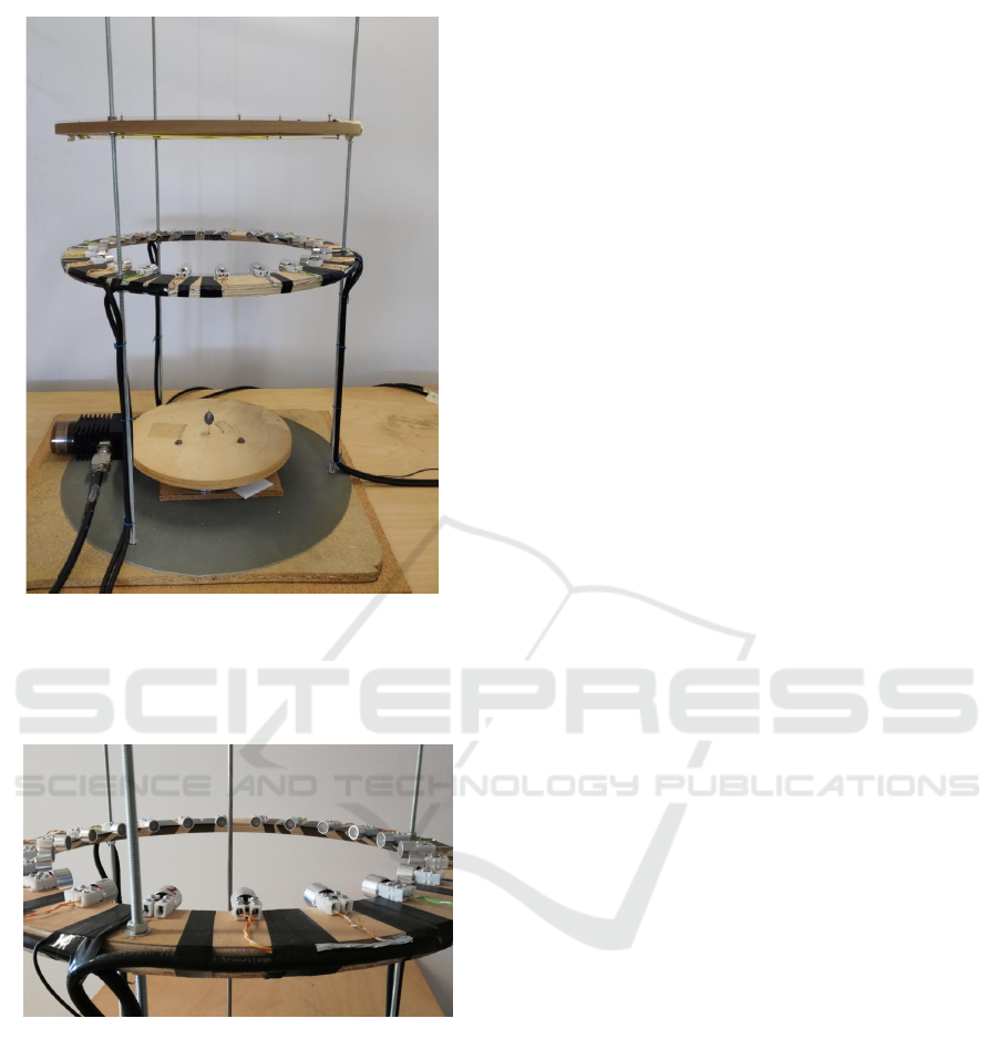
Figure 2: A picture of the laboratory-developed US imaging
system. Sensors (1 Tx, 21 Rx) are located on a wooden ring.
The multiview-multistatic configuration is realised via a ro-
tating table the targets are located on, in order to virtually
simulate the movement of the sensors ring.
Figure 3: A simple test case with a single metallic cylinder
located on the rotating table.
The sensors used as transmitter and receiver are, re-
spectively, 40LT16 and 40LR16 both manufactured
by SensComp.
The scattered US waves received by 40LR16 sen-
sors are acquired by PCI-6251 analog-to-digital con-
verters boards manufactured by National Instruments.
These boards have a sixteen-bit resolution and a maxi-
mum sampling rate of 1.25 MS/s. In the measurement
campaign, the sampling frequency was fixed at 100
kHz with sixteen-bit precision. A LabVIEW code was
employed to manage the acquisition steps, including
the control of ROI rotation. The acquisition proto-
col consists of a stepped movement and in each posi-
tion the system stops and acquires for 0.5 second, and
then goes on to the next angular position. Once ac-
quired, the signals were pre-processed in Matlab en-
vironment. At this step, the signals were filtered in the
frequency domain in order to extract only the compo-
nent at 40 kHz. Subsequently, the the beat signals
(amplitude and phase) are measured.
In order to make available several heterogeneous
dataset, different scenarios have been implemented.
More in detail, objects of different materials (metal,
wood, polystyrene) and shapes (circular, rectangular
and irregular sections) have been acquired. Within
this manuscript, results related to metallic cylinders
(4-mm diameter) are reported. A picture of the con-
sidered acquisition is shown in Fig 3.
In Fig. 4, the reconstructed sections in case of one
(left image) and two (right image) cylinders are re-
ported. It is worth to note that, despite of the high con-
trast between the mechanical properties of the metal
and the air, the shape and the location of the targets
are correctly identified, appearing in a ring shape (Fig.
4a). This behaviour in the case of impenetrable ob-
jects is in accordance with the literature (Bevacqua
and Isernia, 2017), as the mechanical vibrations in-
duced by an external active source in the targets only
exist on the boundary of targets support. However,
even though the non-linearity of the scenario under
test becomes more stressed in the case of two cylin-
ders (Fig. 4b), it is still possible to identify the tar-
gets correctly, both in terms of shape and position.
future acquisitions related to all the considered sce-
narios will we uploaded on-line and made available
on request.
4 CONCLUSION
In this manuscript, a tomographic in-house
ultrasound-based multiview-multistatic imaging
system has been designed, built and tested. The
performance assessment on cylindrical metallic
objects via a classic inversion approach (i.e., the
linear sampling method) is reported.
It is worth to underline that the relationship be-
tween the scattered field and the object to be retrieved
defines a problem that is non-linear and ill-posed.
In order to cure this instability, some regularisation
strategies are required to avoid unreliable recoveries.
From this point of view, the use of multiview data can
partially overcome this limitation, especially for noise
reduction. Moreover, the use of multi-frequency data
could improve considerably the available independent
information, allowing better reconstructions, which
A Tomographic Multiview-Multistatic Ultrasound System for Biomedical Imaging Applications
277
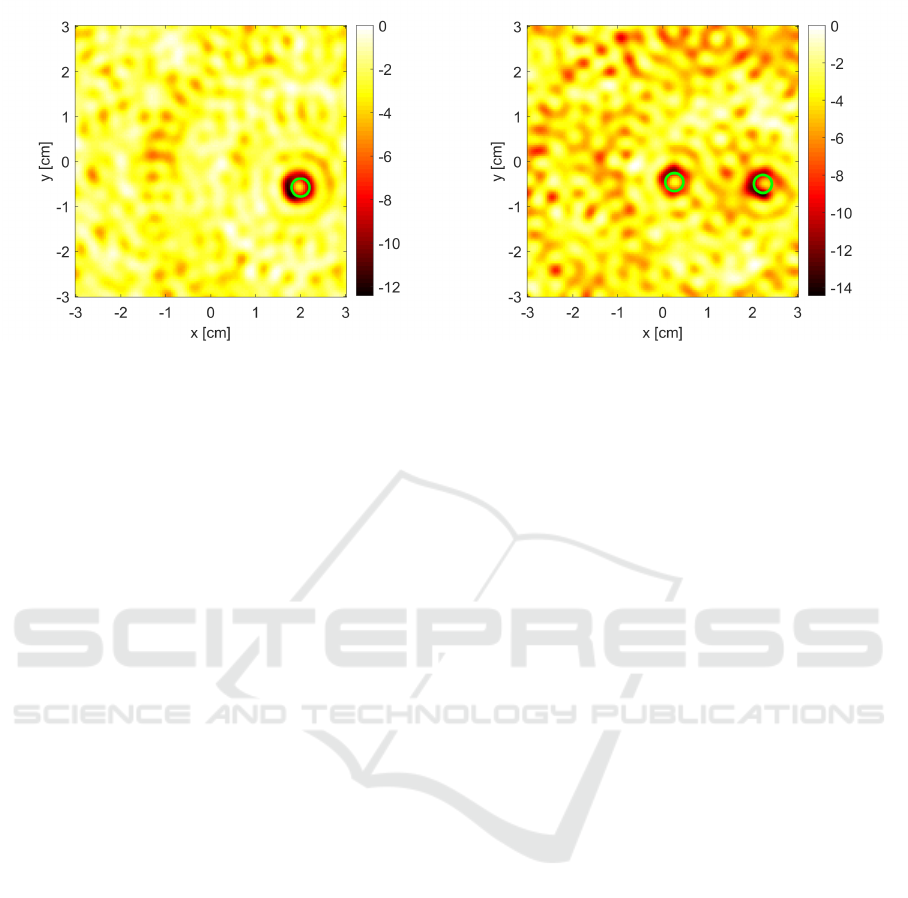
(a) (b)
Figure 4: Imaging results of the data acquired by the proposed prototype via the linear sampling method. (a) single cylinder
and (b) two-cylinder reconstructions. The references are the light-green circles.
can be easily implemented by employing proper hard-
ware solutions.
Even though the proposed system is air-coupled
and provides a qualitative imaging of targets support,
it can be easily generalised to the underwater acoustic
imaging case, which represents a convenient, prelim-
inary test before moving to the imaging of human tis-
sues. For instance, in the framework of breast cancer
imaging, the use of this kind of systems could be ben-
eficial for early diagnosis, since it is safe and allows
a frequent screening which may be a complementary
exam to support cancer diagnosis and advancing clas-
sic ultrasound.
Future work will focus on the design and build-
ing of a water-matched prototype for the performance
assessment with breast tissue mimicking phantoms.
REFERENCES
Abdollahi, N., Kurrant, D., Mojabi, P., Omer, M., Fear,
E., and LoVetri, J. (2019). Incorporation of ultra-
sonic prior information for improving quantitative mi-
crowave imaging of breast. IEEE Journal on Mul-
tiscale and Multiphysics Computational Techniques,
4:98–110.
Alqadah, H. F. (2016). A compressive multi-frequency lin-
ear sampling method for underwater acoustic imaging.
IEEE Transactions on Image Processing, 25(6):2444–
2455.
Ambrosanio, M., Autieri, R., and Pascazio, V. (2014). A
compressive sensing based approach for microwave
tomography and gpr applications. In 2014 IEEE Geo-
science and Remote Sensing Symposium, pages 3144–
3147. IEEE.
Belkebir, K., Kleinman, R. E., and Pichot, C. (1997).
Microwave imaging-location and shape reconstruc-
tion from multifrequency scattering data. IEEE
Transactions on Microwave Theory and Techniques,
45(4):469–476.
Bevacqua, M. T. and Isernia, T. (2017). Shape reconstruc-
tion via equivalence principles, constrained inverse
source problems and sparsity promotion. Progress In
Electromagnetics Research, 158:37–48.
Bevacqua, M. T. and Palmeri, R. (2019). Qualitative meth-
ods for the inverse obstacle problem: A comparison of
experimental data. Journal of Imaging, 5(4):47.
Colton, D. and Kress, R. (2012). Inverse acoustic and elec-
tromagnetic scattering theory, volume 93. Springer
Science & Business Media.
Crocco, L., Di Donato, L., Catapano, I., and Isernia, T.
(2012). An improved simple method for imaging the
shape of complex targets. IEEE Transactions on An-
tennas and Propagation, 61(2):843–851.
Cui, T. J., Qin, Y., Wang, G.-L., and Chew, W. C. (2004).
Low-frequency detection of two-dimensional buried
objects using high-order extended born approxima-
tions. Inverse Problems, 20(6):S41.
Haynes, M. and Moghaddam, M. (2010). Large-domain,
low-contrast acoustic inverse scattering for ultrasound
breast imaging. IEEE Transactions on Biomedical En-
gineering, 57(11):2712–2722.
Mojabi, P. and LoVetri, J. (2015). Ultrasound tomography
for simultaneous reconstruction of acoustic density,
attenuation, and compressibility profiles. The Journal
of the Acoustical Society of America, 137(4):1813–
1825.
Mojabi, P. and LoVetri, J. (2017). Evaluation of balanced
ultrasound breast imaging under three density profile
assumptions. IEEE Transactions on Computational
Imaging, 3(4):864–875.
Omer, M., Mojabi, P., Kurrant, D., LoVetri, J., and Fear,
E. (2018). Proof-of-concept of the incorporation
of ultrasound-derived structural information into mi-
crowave radar imaging. IEEE Journal on Multiscale
and Multiphysics Computational Techniques, 3:129–
139.
BIODEVICES 2020 - 13th International Conference on Biomedical Electronics and Devices
278

Pastorino, M. (2010). Microwave imaging, volume 208.
John Wiley & Sons.
Pierri, R., Persico, R., and Bernini, R. (1999). Informa-
tion content of the born field scattered by an embedded
slab: multifrequency, multiview, and multifrequency–
multiview cases. JOSA A, 16(10):2392–2399.
Salucci, M., Sartori, D., Anselmi, N., Randazzo, A., Oliv-
eri, G., and Massa, A. (2013). Imaging buried objects
within the second-order born approximation through
a multiresolution-regularized inexact-newton method.
In 2013 International Symposium on Electromagnetic
Theory, pages 116–118. IEEE.
Tikhonov, A. N., Goncharsky, A., Stepanov, V., and Yagola,
A. G. (2013). Numerical methods for the solution of
ill-posed problems, volume 328. Springer Science &
Business Media.
A Tomographic Multiview-Multistatic Ultrasound System for Biomedical Imaging Applications
279
