
High-level Partitioning and Design Space Exploration for Cyber Physical
Systems
Daniela Genius
1
, Ilias Bournias
1
, Ludovic Apvrille
2
and Roselyne Chotin
1
1
Sorbonne Université, LIP6, CNRS UMR 7606, Paris, France
2
LTCI, Télécom Paris, Université Paris-Saclay, Paris, France
Keywords:
Embedded Systems, Analog/Mixed Signal Design, Activity Diagrams, Virtual Prototyping.
Abstract:
Virtual prototyping and co-simulation of mixed analog/digital embedded systems have emerged as a promising
research topic, but usually assume an already Hardware/Software partitioned system. The paper presents a
new approach for high-level system partitioning of such mixed systems, by expressing the structure and the
behaivour of the analog parts with SysML diagrams. A tool already able to handle some aspects of analog
design after partitioning has been extended to be able to handle partitioning, thus completing the methodology.
As a real-world case study, we show the design of the hardware part of a medical application.
1 INTRODUCTION
Embedded systems are often built upon heteroge-
neous hardware composed of Field Programmable
Gate Arrays (FPGAs), Digital Signal Processors
(DSPs), hardware accelerators, analog/mixed signal
(AMS) and radio frequency (RF) circuits on the one
hand, System on chip (SoC) running the software on
general purpose processors on the other. The large va-
riety of hardware combinations to explore — such as
which parts should run on the SoC, which should be
implemented on FPGA, or if it is beneficial to cast
certain functionality into Application Specific Inte-
grated Circuits (ASIC)? — opens up a vast design
space which is difficult to handle.
AMS and RF components should be considered
differently since the function they implement cannot
be realized in software nor on an FPGA. However,
their functionality can be represented in an abstract
way, while keeping relevant information.
An approach presented in (Genius et al., 2019)
does not tackle system-level modeling, in contrast to
the contribution presented in the paper, which thus
completes our methodology for AMS systems.
The paper proposes a high-level representation
of Cyber Physical systems that includes high-level
models of all these components —including analog
components— which are yet sufficiently precise to
detect design problems related to the interaction of
analog and digital parts.
In summary, the paper describes the abstraction
we propose and how it can be used for fast design
space exploration. After discussing related work in
Section 2, we introduce the underlying concepts in
Section 3. Our contribution is described in Section 4
and applied to a larger case study in Section 5 before
we conclude.
2 RELATED WORK
The following tools target analog/mixed signal or
multi-domain design and co-simulation.
Ptolemy II (Ptolemy.org, 2014) is based upon the
data-flow model. It addresses digital/analog systems
by defining several sub domains. Instantiation of el-
ements controlling time synchronization between do-
mains is left to the designer.
Metro II (Davare et al., 2007) is based on hi-
erarchical, high level, models. So-called Adapters
are used for data synchronization between compo-
nents belonging to different Models of Computation
(MoCs), yet the model designer still has to implement
time synchronization. As a common simulation ker-
nel handles the entire process execution (digital and
analog), MoCs are not well separated.
Modelica (Fritzson and Engelson, 1998) is an
object-oriented modeling language for component-
oriented systems containing e.g. mechanical, elec-
trical, electronic and hydraulic components. Classes
contain sets of equations that can be translated into
objects running on a simulation engine. Yet, since
time synchronization is not predefined, the simulation
engine must manipulate objects in a symbolic way in
order to determine an execution order between com-
84
Genius, D., Bournias, I., Apvrille, L. and Chotin, R.
High-level Partitioning and Design Space Exploration for Cyber Physical Systems.
DOI: 10.5220/0009171600840091
In Proceedings of the 8th International Conference on Model-Driven Engineering and Software Development (MODELSWARD 2020), pages 84-91
ISBN: 978-989-758-400-8; ISSN: 2184-4348
Copyright
c
2022 by SCITEPRESS – Science and Technology Publications, Lda. All rights reserved

ponents of different MoCs. Linking simulations with
different Models of Computation can be done by us-
ing e.g. the Functional Mock-up Interface (Blochwitz
et al., 2011), closely related to the Modelica tools.
SystemC AMS extensions (Barnasconi et al.,
2016)(Vachoux et al., 2003), is a library of C++
classes based on SystemC (IEEE, 2011), extending of
SystemC with AMS and RF features. In the scope of
the BeyondDreams project (Beyond Dreams Consor-
tium, 2011), a mixed analog-digital systems proof-of-
concept simulator has been developed, based on the
SystemC AMS extension standard (Einwich, 2016).
3 BASIC CONCEPTS
Let us briefly introduce the two fundamental concepts
and associated tools which are the basis of the present
contribution.
3.1 Multi-level Model-based Design
Model-based engineering of (digital) embedded sys-
tems can be performed at different abstraction levels,
commonly grouped into two subsets: functional and
partitioning (high level), software design and deploy-
ment (low level). Specific SysML views and diagrams
have been defined for each abstraction level. Software
and hardware tasks to be partitioned are first captured
within the functional abstraction level. Then, func-
tions and their communications are mapped to ab-
stract hardware components.
After partitioning, software tasks can be further
detailed and then deployed on more concrete hard-
ware components. Thus, software deployment in-
tends to experiment the interaction of software with
all other components (digital and analog).
For closely analyzing the deployment of software
tasks, Analog/Mixed Signal components have to be
precisely described in order to generate a represen-
tative virtual prototype (e.g. in SystemC): there, we
assume that these componentns play a role similar
to hardware accelerators. Yet, at higher abstraction
level, i.e. at partitioning level, it is challenging to rep-
resent them abstractly without losing important pre-
cision. Indeed, since their semantics strongly differs
from the one of digital components, the interactions
between the two models of computations has to be
closely captured. The paper further elaborates on the
semantics aspects, and how these components can ef-
ficiently be captured at a high level of abstraction us-
ing SysML diagrams.
3.2 SystemC AMS
In SystemC AMS, digital components are described
with a Discrete Event (DE) model, while analog com-
ponents are described with the Timed Data Flow
(TDF) Model of Computation, itself based on the
timeless Synchronous Data Flow (SDF) semantics
(Lee and Messerschmitt, 1987).
Discrete Event Model of Computation. A
discrete-event simulation abstracts a system as a
discrete sequence of events in time, where each event
signals a change of state, in contrast to continuous
simulation in which the system state changes contin-
uously over time. A well-known example of a DE
framework is Ptolemy II (Ptolemy.org, 2014). DE
models in SystemC AMS are essentially SystemC
descriptions, using its event-based simulation kernel
(IEEE, 2011).
Timed Data Flow Model of Computation. In
Timed Data Flow (TDF), continuous functions are
sampled at discrete intervals. A TDF module is de-
scribed with an attribute representing the time step
and a processing function. A processing function is
a mathematical function depending on the module in-
puts and/or internal states. At each time step, a TDF
module first reads a fixed number of samples from
each of its input ports, then executes its processing
function, and finally writes a fixed number of samples
to each of its output ports. TDF modules have the
following attributes:
A B Y
R= 1
D= 1
Tm= 6 ms Tm= 4 ms
Tp= 4 ms
R= 3
Tp= 2 ms
D= 0
R= 2
D= 0
Tp= 2 ms
TDF Cluster
Figure 1: TDF cluster with two TDF and one DE module.
• Module Timestep (Tm) denotes the period during
which the module will be activated. One module
will only be activated if there are enough samples
available at its input ports.
• Rate (R). Each module reads or writes a fixed
number of data samples each time it is activated.
This number is annotated to the ports and it is
known as the port rate.
• Port Timestep (Tp) is the period between module
port activation. It also denotes the time interval
between two samples that are read or written.
High-level Partitioning and Design Space Exploration for Cyber Physical Systems
85

• Delay (D). A delay D can be assigned to a port
to make it store a given number of samples each
time it is activated, and read or write them in the
next activation.
Figure 1 shows a TDF cluster in the representation
defined in the SystemC AMS standard. (Barnasconi
et al., 2016). The DE module Y is represented as a
white block, the two TDF modules A and B as gray
blocks. TDF ports are black squares, TDF converter
ports are black and white squares, and DE ports are
white squares. TDF signals are arrows. The converter
port, shown as black-and white squares, serves as in-
terfaces between the TDF and DE MoC. The module
Timestep of A is 6ms, its port Timestep 2ms and its
Rate 3. B has a port and module Timestep of 4ms and
a Rate of 1. B has a Delay of 1.
The module Timestep must be consistent with the
rate and time step of any port within a module. The
relation between Timesteps and Rates is as follows,
where T
m
is the module Timestep, T
pi
and T
po
are the
input and output port Timesteps, R
pi
and R
po
the input
and output port Rates, respectively:
T
m
= T
pi
× R
pi
= T
po
× R
po
Once this consistency has been validated for a particu-
lar cluster by propagating the parameters downstream
and upstream (Accellera Systems Initiative, 2010),
the cluster may operate at any frequency. In the ex-
ample shown in Figure 1, A and B are TDF modules,
Y is a DE module, there are TDF ports between A and
B outputs to a converter port. Port Rates, Delays and
Timesteps as well as module Timesteps are given for
the TDF modules. The equation is satisfied for mod-
ules A (6ms = 2ms × 3) and B (4ms = 4ms × 1) and a
valid schedule is A-B-A-B-B.
SystemC AMS Top Cell. TDF clusters can contain
TDF and DE blocks; in SystemC AMS, they are in-
stantiated together in the main SystemC program of
a common top cell. Whenever TDF and DE modules
coexist in a SystemC AMS specification, they are co-
simulated: the SystemC kernel controls the AMS ker-
nel which runs continuously until interrupted. When
a SystemC AMS simulation is being executed, the ex-
ecution of the SystemC simulation kernel is blocked,
while the SystemC AMS simulation kernel continues
running. The DE kernel must not run ahead of the
AMS kernel; otherwise, causality issues arise. Re-
cent work shows how to check causality aspects be-
fore simulation (Andrade et al., 2015) or even before
code generation (Genius et al., 2019); the latter ap-
proach has been adopted in our tool.
4 METHOD
The paper proposes an extension of the high-level
modeling and verification capabilities of an existing
framework, TTool, (Apvrille, 2003) in order to better
design complex applications, where analog parts in-
teract with each other as well as with digital domains.
In TTool, functionality and hardware are described
with SysML-like diagrams. A C++ simulation on par-
titioning level is generated automatically from these,
as is the virtual prototype from the SysML-like repre-
sentation of hardware, software and deployment.
Our idea is to capture the behavior of each Sys-
temC AMS module with an extended SysML activ-
ity diagram; the latter are already used for describ-
ing the behavior of discrete components, as explained
in (Apvrille et al., 2006). In Figure 2, the red cir-
cle points out AMS extensions described in the paper.
Previously, distinction was only made between func-
tional blocks mapped to hardware or software. No
particular attention was given to analog blocks.
4.1 Modeling and Verification
4.1.1 Structural Modeling
A Partitioning P is defined as a set of models P =
(F, A, M), with F a Functional Model, A an Archi-
tecture Model, and M a Mapping Model. The Func-
tional Model is defined as F = (T, C) where T is a set
of Tasks, and C is a set of Communications between
tasks. A Task t is defined as t = (Attr, B) with Attr
a set of Attributes, and B a behavior. From a SysML
point of view, block definition and internal block dia-
grams are used to capture functions and architectural
components. Mapping is performed with allocations.
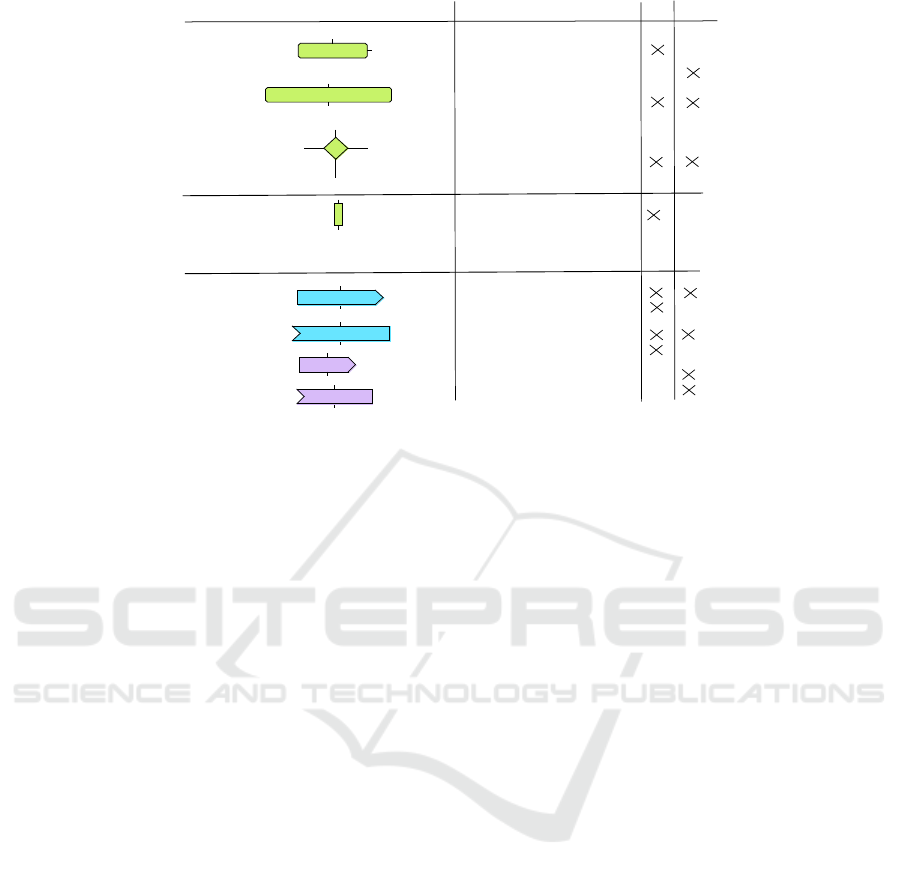
4.1.2 Behavioral Modeling
Behavioral diagrams contain among others control
flow in the form of non-deterministic and guarded
choices, and general control operators. Specific op-
erators can be used for read and write operations on
channels, and sending and receiving of events. All
these are shown on the left hand side of Figure 3. A
Behavior
B = (Ctrl, CommOp, CompOp, Con())
consists of interconnected Control Operators Ctrl,
Communication Operators CommOp and Complex-
ity operators CompOp modeling the complexity of
algorithms through the description of a min/max in-
terval of integer/float/custom operations. Con() gives
all connections between operators (previous to next).
MODELSWARD 2020 - 8th International Conference on Model-Driven Engineering and Software Development
86

Final
software
code
Refinements
VHDL/Verilog
SystemC-
AMS
Virtual Prototype
Deployment
Hardware
design
Hardware
Abstractions
Simulation
and
Verification
Micro Kernel
MPSoC
Model
Partitioning
Level
Software
Design
Level
HW/SW Partitioning
Functional
Software Design
Hardware
model
Figure 2: Methodology: Integration in TTool’s partitioning level (adapted from (Genius et al., 2019)).
The left hand side of Figure 3 shows typical operators
and their (basic) translation into SystemC AMS.
4.2 Modeling DE Modules
DE modules can easily be captured as extra functions.
One activity diagram can be associated to them, as for
other functions.
• To capture the semantics of transfer of data be-
tween DE modules, (usual) communication be-
tween functions can be used. Similarly, the be-
havior of DE modules can use communication op-
erators of activity diagrams.
• Choices (that later will become "if" statements
in the sc_method) can be translated into guarded
branch control structures in the activity diagram.
• The estimated execution time of the module is
captured with a complexity operator in the activ-
ity diagram. These estimations are meant to be
refined at software design level by capturing e.g.
a more concrete algorithm. Then, the deploy-
ment of software leads to executing a virtual pro-
totype from which cycle-accurate values can be
obtained. These precise values can then be fed
back into activity diagrams.
4.3 Modeling TDF Modules and
Clusters
Capturing TDF at a high abstraction level is less ob-
vious than for DE modules since our diagrams have a
discrete-based semantics
The structure of TDF clusters supports only data
channels, as all communication between modules is
done by exchange of data samples and activation is
based on data reception. Clusters regrouping several
TDF and DE modules are represented by compound
modules in block diagrams.
From a behavioral point of view (captured in ac-
tivity diagrams):
• Branches stemming from choices (simulation
code relies on "if" statements in the TDF pro-
cessing function) can be directly translated into
guarded branch control structures in the activity
diagram.
• A TDF Module Timestep is abstracted with a com-
plexity operator. The schedule, i.e. the execu-
tion order of TDF modules in its cluster, must be
known. It is either estimated or derived from the
SystemC AMS model, if the latter already exists.
• Activity diagrams support read and write opera-
tions on channels. They allow to specify a num-
ber of data samples written to/read from a chan-
nel, which can be interpreted as the port Rate at
which samples are written to/read from a port in
TDF.
• Infinite repetition of the cluster’s schedule is cap-
tured by an infinite loop in the activity diagram.
• To model transition between TDF and DE, we use
composite components. A composite component
may contain either TDF or DE modules but not
both; converter ports are modeled by composite
ports. TDF converter ports are represented by
composite ports.
Port Timesteps are not represented in the Functional
View, neither are Delays: they are to be used at soft-
ware/hardware design level, in the SystemC AMS
High-level Partitioning and Design Space Exploration for Cyber Physical Systems
87
chan
out(N)
N time units
Loop for ever
[guard0] [guard1]
[guard2]
chan
in(N)
for(i=0;i<N;i = i+1)
inside loop
exit loop
for(i=0; i<N; i=i+1){...}
void processing(){...}
if(guard0){...}
elsif(guard1){}
else{...}
port.set_rate(N);
out.write();
in.read();
module.set_timestep(N,unit);
Activity Diagram
SystemC-AMS
port.set_rate(N);
Control
operators
Complexity
operator
Communication
operators
evt
in()
evt
out()
void main_func(){...}
TDF
DE
out.notify();
in.wait();
Figure 3: Relation between operators in activity diagrams and their counterpart in SystemC AMS.
representation, in order to calculate the schedule and
enforce causality (see Section 3.2).
Figure 3 shows the relation between TDF/DE
cluster and activity diagrams.
4.4 Mapping
At partitioning level, a mapping model is built upon
abstract hardware components: Communication, Ex-
ecution and Storage Nodes. Hardware components
are highly abstracted: a CPU is defined as a set of
parameters such as an average cache-miss ratio, go-
to-idle time, context switch penalty, etc. We take into
consideration the following execution nodes:
• Central processing Unit (CPU)
• Hardware accelerator (HWA)
• Field programmable Gate Array (FPGA)
Mapping involves allocating tasks (i.e. blocks of the
Functional View) onto the architectural model. A task
mapped to a processor will be implemented in soft-
ware, while a task mapped to a hardware accelerator
or FPGA will be implemented in hardware. In the
case of CPUs or FPGAs, several tasks can be mapped
to the same node. On the contrary, only one task can
be allocated to a hardware accelerator. Simulation of
mapping models helps understanding system perfor-
mance.
5 CASE STUDY
The following case study illustrates high-level mod-
eling for design space exploration. It stems from the
EchOpen project (EchOpen community, 2017), where
system-level designers cooperate closely with hard-
ware designers, with the aim of designing low-cost
and portable echography device for pre-echography
medical exploration, primarily for emerging countries
but also in case of difficult circumstances (Tse et al.,
2014) (Mancuso et al., 2014).
The objective of the system is to receive data sam-
ples sent by the probe of the ultrasound device, to
extract the useful signal and then to store them to a
memory before they are sent to the smartphone for
processing images.
We simulate the probe by a TDF modeule repre-
senting a sine wave generator (SineGenerator). The
first part of the Envelope Detection model itself is the
analog-digital converter (ADC) which takes the sam-
ples from the probe and converts them to digital val-
ues.
The role of envelope detection (Qiu et al., 2012) is
to extract the useful signal: x samples are compared
to those produced by a sample generator (decimation
rate defined by the designer) and the highest value is
extracted among them. Envelope detection is mod-
eled as digital (DE) blocks, and the entire function-
ality (a composite component) is meant to be imple-
mented on FPGA in the first place. Design space ex-
ploration may later indicate that running as software
on a general purpose processor/DSP (like the ones on
a smartphone) suffices. Finally, the values are stored
MODELSWARD 2020 - 8th International Conference on Model-Driven Engineering and Software Development
88
ScanConversion
toSoC
fromSoC
SignalAcquisition
SineGenerator
sineout
ADC
+ threshold : Natural;
+ i = 0 : Natural;
sineout
EnvelopeDetection
abscalc
spi
toSoC
fromSoC
comparator
outpready
adcregister
samplegenerator
outpready
sineout
outpready
outputmax
adcregisteroutput
compienable
toSoC
fromSoC
absoutput
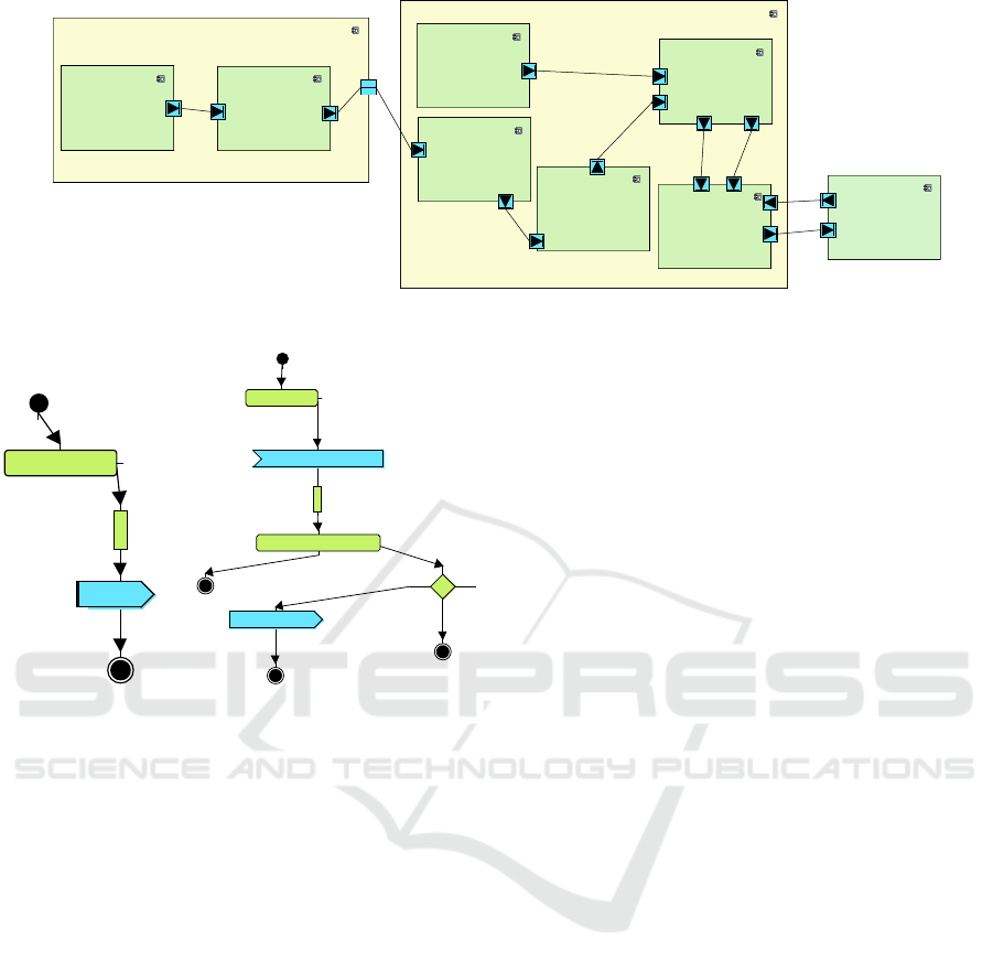
Figure 4: Partitioning level representation.
chl
sineout(1)
Loop for ever
5 us
(a) SineGenerator
Loop for ever
chl
sineout(1)
chl
outputonepoint(1)
5 us
[] [ ]
[else ]
for(i=0;i<4096;i = i+1)
inside loop
exit loop
(b) ADC
Figure 5: Activity diagrams of the analog modules.
in memory in order to be sent on to the processor
for image processing (SPI module). The SPI mod-
ule waits until the envelope detection for the whole
image is completed and then sends it on to the SoC
interface. The processor then implements image pro-
cessing (scan conversion (Sikdar et al., 2001)).
5.1 Partitioning Level
Figure 4 shows the functional view. Green blocks
represent functional components connected through
ports to data channels (in blue). Yellow blocks rep-
resent composite components. The analog modules
SineGenerator and ADC can now be captured as spe-
cific tasks, whose behavior is captured within activity
diagrams (Figure 5).
In Figure 6, the SineGenerator and ADC modules
are mapped to hardware accelerators, EnvelopeDetec-
tion to the (digital) FPGA, finally ScanConversion to
the SoC. While the former functionality will be thus
implemented in hardware, the latter will be imple-
mented in software.
Simulation and Formal Verification. Diagrams
are converted into C++ before being simulated or for-
mally verified (the simulation engine can generate
a reachability graph, not shown here). The simula-
tion engine is predictive: each processing element ad-
vances at its own pace until a system event (data trans-
fer, a synchronization event, etc.) invalidates current
transactions. Then, the latter are cut back as much
as necessary in the past, and the simulation continues
from the cut transactions.
Analog components are modeled as hardware ac-
celerators. The mapping view contains FPGA, at this
level of abstraction, simply simulated as a n-core pro-
cessors, with n being the number of tasks mapped.
5.2 Software Design Level
One partitioning is satisfactory, the software design
level includes a way to validate models with more
concrete hardware models. This validation is per-
formed thanks to a model-to-virtual-prototype trans-
formation. There, a specific SysML block diagram is
used to capture TDF clusters, including modules and
port rates, delays, modules and port Timesteps (Ge-
nius et al., 2019).
5.2.1 Validation
From a TDF block diagram, a coherent schedule is
then computed, and causality issues between DE and
TDF modules automatically indicated. These steps
are performed in a so-called validation window. Once
the cluster schedule is validated, the virtual prototype,
which can be a stand-alone SystemC AMS or a com-
bination of SystemC AMS and SoC platform, includ-
ing Operating System and software, can be generated.
Stand-alone AMS code can be used while the digital
part of the platform has not yet been modeled. We
first compare the generated code against a handwrit-
ten version, initially at our disposition. The two are
not identical – automatically generated code contains
High-level Partitioning and Design Space Exploration for Cyber Physical Systems
89
<<FPGA>>
FPGA0
Application::spi
Application::abscalc1
Application::comparator1
Application::adcre1
Application::samplegenerator
<<BUS-RR>>
Bus0
<<CPU>>
CPU0
Application::ScanConversion
<<MEMORY>>
Memory0
<<HWA>>
HWA0
Application::SineGenerator
<<HWA>>
HWA0
Application::ADC
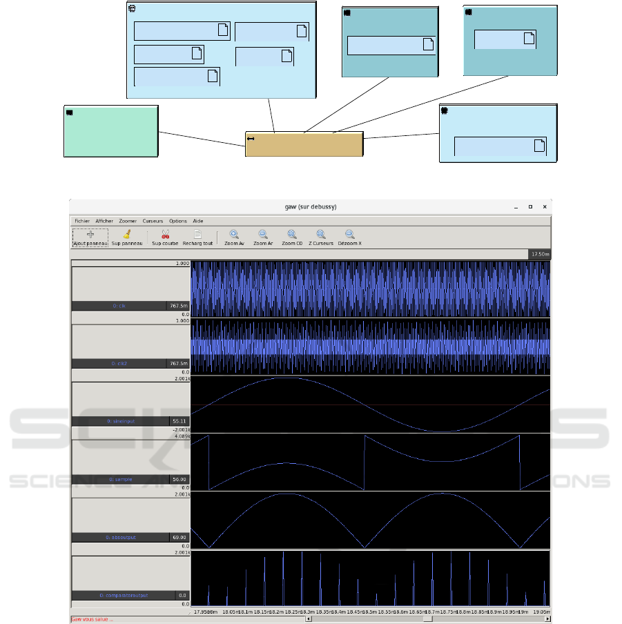
Figure 6: Partitioning level architecture and mapping diagram.
Figure 7: Analog trace generated from the SystemC AMS simulation.
canonical names and respects a predefined structure –
but yield identical simulation results.
Yet,the integration of SystemC AMS made it nec-
essary to add facilities for tracing analog, thus contin-
uous, signals, in the virtual prototype.
In Figure 7, only the most relevant signals are
shown (Quillevere, 2019). The first curve is the sam-
pling frequency of the ADC and must be faster than
the clock of the digital part. The second curve is the
clock of the FPGA, the third the input from the trans-
ducer (raw data of the probe). The fourth curve dis-
plays the samples from the ADC (analog part), the
fifth the absolute value which is part of envelope de-
tection, i.e. digital part, after signal decimation. The
sixth curve is the calculation of the maximum value
among decimated absolute values.
6 DISCUSSION AND FUTURE
WORK
We show how to take into account digital and ana-
log aspects of an embedded system from the very first
modeling phases onwards. For that purpose, we ex-
tend a partitioning tool with new SysML models able
MODELSWARD 2020 - 8th International Conference on Model-Driven Engineering and Software Development
90

to capture SystemC AMS components in an abstract
but sufficiently representative way. Thanks to this in-
tegration, we can reuse the existing simulation meth-
ods at partitioning level of TTool, relying on the gen-
eration of C++ code and a predictive and discrete sim-
ulation engine. Yet, more detailed tests should reveal
whether our abstract model of converter ports as com-
posite ports guarantees sufficient precision or whether
the functional simulator has to be further enhanced.
Simulation parameters on the partitioning level
can be initially based on first assumptions; when
software design and deployment level have been de-
signed, more accurate estimations of the execution
time (DE) and valid schedules and parameters for
TDF can be fed back to the partitioning levels.
The paper focuses on the SystemC AMS part of
the system, whereas our tool can already generate
code for co-simulation with a System-on-Chip (SoC)
platform running other software components in full-
system simulation under a lightweight operating sys-
tem. In a next step of the project, the complete scan
conversion code will be integrated on the SoC.
REFERENCES
Accellera Systems Initiative (2010). SystemC AMS exten-
sions Users Guide, Version 1.0.
Andrade, L., Maehne, T., Vachoux, A., Ben Aoun, C.,
Pêcheux, F., and Louërat, M.-M. (2015). Pre-
Simulation Formal Analysis of Synchronization Is-
sues between Discrete Event and Timed Data Flow
Models of Computation. In Design, Automation and
Test in Europe, DATE Conference.
Apvrille, L. (2003). Webpage of TTool,
https://ttool.telecom-paris.fr/.
Apvrille, L., Muhammad, W., Ameur-Boulifa, R., Coud-
ert, S., and Pacalet, R. (2006). A uml-based environ-
ment for system design space exploration. In 2006
13th IEEE International Conference on Electronics,
Circuits and Systems, pages 1272–1275. IEEE.
Barnasconi, M., Einwich, K., Grimm, C., Maehne, T., and
Vachoux, A. (2016). SystemC AMS Extensions 2.0
Language Reference Manual. Accellera systems ini-
tiative.
Beyond Dreams Consortium (2008-2011). Be-
yond Dreams (Design Refinement of Embed-
ded Analogue and Mixed-Signal Systems).
http://projects.eas.iis.fraunhofer.de/beyonddreams.
Blochwitz, T., Otter, M., Arnold, M., Bausch, C., Elmqvist,
H., Junghanns, A., Mauß, J., Monteiro, M., Neid-
hold, T., Neumerkel, D., et al. (2011). The functional
mockup interface for tool independent exchange of
simulation models. In 8th Int. Modelica Conference,
Dresden, Germany, number 063, pages 105–114.
Davare, A., Densmore, D., Meyerowitz, T., Pinto, A.,
Sangiovanni-Vincentelli, A., Yang, G., Zeng, H., and
Zhu, Q. (2007). A next-generation design framework
for platform-based design. In DVCon, volume 152.
EchOpen community (2017). Designing an
open-source and low-cost echo-stethoscope.
http://www.echopen.org/.
Einwich, K. (2016). SystemC AMS PoC2.1 Library,
COSEDA, Dresden.
Fritzson, P. and Engelson, V. (1998). Modelica—a uni-
fied object-oriented language for system modeling
and simulation. In European Conference on Object-
Oriented Programming, pages 67–90. Springer.
Genius, D., Cortés Porto, R., Apvrille, L., and Pêcheux,
F. (2019). A tool for high-level modeling of
analog/mixed signal embedded systems. In MODEL-
SWARD.
IEEE (2011). SystemC. IEEE Standard 1666-2011.
Lee, E. A. and Messerschmitt, D. G. (1987). Synchronous
data flow. Proceedings of the IEEE, 75(9):1235–1245.
Mancuso, F. J. N., Siqueira, V. N., Moisés, V. A., Gois,
A. F. T., Paola, A. A. V. d., Carvalho, A. C. C., and
Campos, O. (2014). Focused cardiac ultrasound using
a pocket-size device in the emergency room. Arquivos
brasileiros de cardiologia, 103(6):530–537.
Ptolemy.org, editor (2014). System Design, Modeling, and
Simulation using Ptolemy II.
Qiu, W., Yu, Y., Tsang, F. K., and Sun, L. (2012). An fpga-
based open platform for ultrasound biomicroscopy.
IEEE transactions on ultrasonics, ferroelectrics, and
frequency control, 59(7):1432–1442.
Quillevere, H. (2019). Gtk Analog Wave viewer.
Sikdar, S., Managuli, R., Mitake, T., Hayashi, T., and Kim,
Y. (2001). Programmable ultrasound scan conversion
on a media-processor-based system. In Medical Imag-
ing: Visualization, Display, and Image-Guided Proce-
dures, volume 4319, pages 699–711. Int. Society for
Optics and Photonics.
Tse, K. H., Luk, W. H., and Lam, M. C. (2014). Pocket-
sized versus standard ultrasound machines in abdom-
inal imaging. Singapore medical journal, 55(6):325.
Vachoux, A., Grimm, C., and Einwich, K. (2003). Analog
and mixed signal modelling with SystemC-AMS. In
ISCAS (3), pages 914–917. IEEE.
High-level Partitioning and Design Space Exploration for Cyber Physical Systems
91
