
A High Stroke Actuator Micro-mirror Array Designed for Adaptive
Optics
Quan Sun
1,2,3
, Baozhu Yan
1,2,3
and Yi Yang
1,2,3
1
College of Advanced Interdisciplinary Studies, National University of Defense Technology, Changsha, China
2
State Key Laboratory of Pulsed Power Laser Technology, Changsha, China
3
Hunan Provincial Key Laboratory of High Energy Laser Technology, Changsha, China
Keywords: Adaptive Optics, MEMS, High Stroke, Micro-mirror Array.
Abstract: A micro-mirror with large out-of-plane displacement actuator with three polysilicon layers fabrication process
is designed for adaptive optics application. The optimized micro-mirror actuating structure consists of three
individual levers, each of which is actuated by electrostatic attractive force with the plane-parallel structure
to produce a large upward displacement at the end of the long arm of the lever with the lever principle. Finite
element analysis (FEA) models are built to calculate the maximum upward displacement of the long arm. The
actuator with 320 um long arm and 80 um short arm were designed by 2um thick Poly1 layer, while the
electrodes were designed by Poly0 and mirror plate was designed by Poly2 with a polish process afterwards.
The micro-mirrors can be tightly arranged in a hexagonal array to be applied in adaptive optics (AO) system
as a deformable mirror. An AO simulation system is built to test the aberration correction effect of the micro-
mirror array. The results showed that the 61 micro-mirror array is better than 37 micro-mirror array in
aberration correction, which showed good application prospect of this high stoke micro-mirror array in AO
systems.
1 INTRODUCTION
Recently, microelectromechanical systems (MEMS)-
based micromirrors have received much attention.
They have been applied in a wide range of areas, such
as in optical switches (
Chen W. C., et al., 2003) (Tsai
C
., et al., 2015) and displays
(Yan J., et al., 2001)
(Freeman M. O., 2003), high performance imaging
including biomedical imaging (Zhang Y. H., et al.,
2006) (
Manzanera S. , et al., 2011) and astronomy
imaging (Blain Celia, 2013) (
Morzinski K. M. et al.,
2006), and laser-based communication (L. MC A., et
al., 2002) (
Li J., et al., 2005) in adaptive optics.
MEMS-based micromirrors have higher operating
speed and lower mass than traditional technology
fabricated deformable mirrors, and a potential for
lower cost and integration with electronics through
batch micro-fabrication processes. The latest
developments in adaptive optics for compensating
large amplitude, high order wavefront aberrations
have pushed for high stroke, high spatial resolution
deformable mirrors. Many recent papers have
addressed design, modeling and fabrication of various
types of micromirrors with large stroke (
Dagel D. J., et
al., 2006) (Sun Q., et al., 2010) (Lin P. Y., et al.,
2011). The various micromirror prototypes are
fabricated with different processes: commercial
standard processes or custom-designed processes.
Compared with custom-designed processes,
commercial standard processes provide mature and
stable runs, with a low cost and short fabrication cycle
but with strict design rules which limit the
performance of the fabricated device. One of the
industry's longest-running standard processes is
Multi-User MEMS Processes (MUMPs)
(Carter J., et
al., 2005). It provided a three layers fabrication
process and has been widely chosen for micromirror
prototypes fabrication
(Zhang X. M., et al., 2001) (Sun
Q., et al., 2009). The defect of this process is that it is
difficult to make a smooth and flat mirror surface
without polish after Ploy3 deposition. Most of the
micromirrors reported to date employ electrostatic
actuators because of their low power consumptions
and fast response time (Zhang J. L., et al., 2003)
(Chiou J. C., et al., 2007). In most applications,
electrostatic actuators are preferred because of
relatively simple in terms of design and fabrication;
however, it suffers from the pull-in phenomenon,
which limits its useful scan range. In this paper, we
168
Sun, Q., Yan, B. and Yang, Y.
A High Stroke Actuator Micro-mirror Array Designed for Adaptive Optics.
DOI: 10.5220/0009171501680173
In Proceedings of the 8th International Conference on Photonics, Optics and Laser Technology (PHOTOPTICS 2020), pages 168-173
ISBN: 978-989-758-401-5; ISSN: 2184-4364
Copyright
c
2022 by SCITEPRESS – Science and Technology Publications, Lda. All rights reserved
proposed a micromirror with large-stroke (about 8
um) electrostatic actuators designed by upgraded
three layers polysilicon surface micromachining
technology. The micromirror structure has a
hexagonal mirror plate actuated by three levers and
controlled by three electrodes, which exhibits a large
stroke and tip/tilt/piston motion.
In this paper, we proposed an upgraded process
with polish operation after the third polysilicon layer
to design a large stroke micro-mirror. The paper is
organized as follow. Section 2 describes the design
details of micromirror structure with simulation
results by finite element method (FEM) in COMSOL
Multiphysics software which is provided software
solutions for multiphysics modeling by the COMSOL
Group. Section 3 reports two kind of micromirror
arrays applied in adaptive optics simulation system to
compare their compensation effect. And conclusions
are presented in Section 4.
2 DESIGN OF MICROMIRROR
In the fabrication process, polysilicon is used as the
structural material and phosphosilicate glass (PSG) is
used as the sacrificial material. Twelve lithographic
masks are used to pattern seven physical layers. The
physical layers, from the substrate up, are as follows:
0.6μm of nitride (Nitride), 0.5μm of polysilicon
(Poly0), 2.0μm of PSG (Oxide1), 2.0μm of
polysilicon (Poly1), 0.75μm of PSG (Oxide2), 2.5μm
of polysilicon (Poly2) and finally 0.5μm of gold
(Metal), deposited on top of a thin adhesion layer of
chromium. Poly1 and Poly2 are usually used to form
the releasable structural layers, while Poly0 is fixed
and generally used to form addressed electrodes and
electrical interconnects. Nitride is used as electrical
insulation between the polysilicon layer and the
substrate. Metal layer is coated on top of Poly2 to
serve as reflective surface. In order to reach a high fill
rate of micro-mirror array reflect surface, we used
Poly2 to design the mirror plate to a hexagon shape.
As we know, there is residual stress after deposited
polysilicon released, which will make the plate to
bending deformation. One way to reducing the
deformation is increasing the thickness of plate.
While Poly1 is left to be made actuator, we design a
3um wide frame with Poly1 to connect the plate at its
edge. In order to simulate the characters of our
designed micromirror structure, a 3D solid model is
built in COMSOL Multiphysics. The typical material
parameters are acquired from COMSOL material
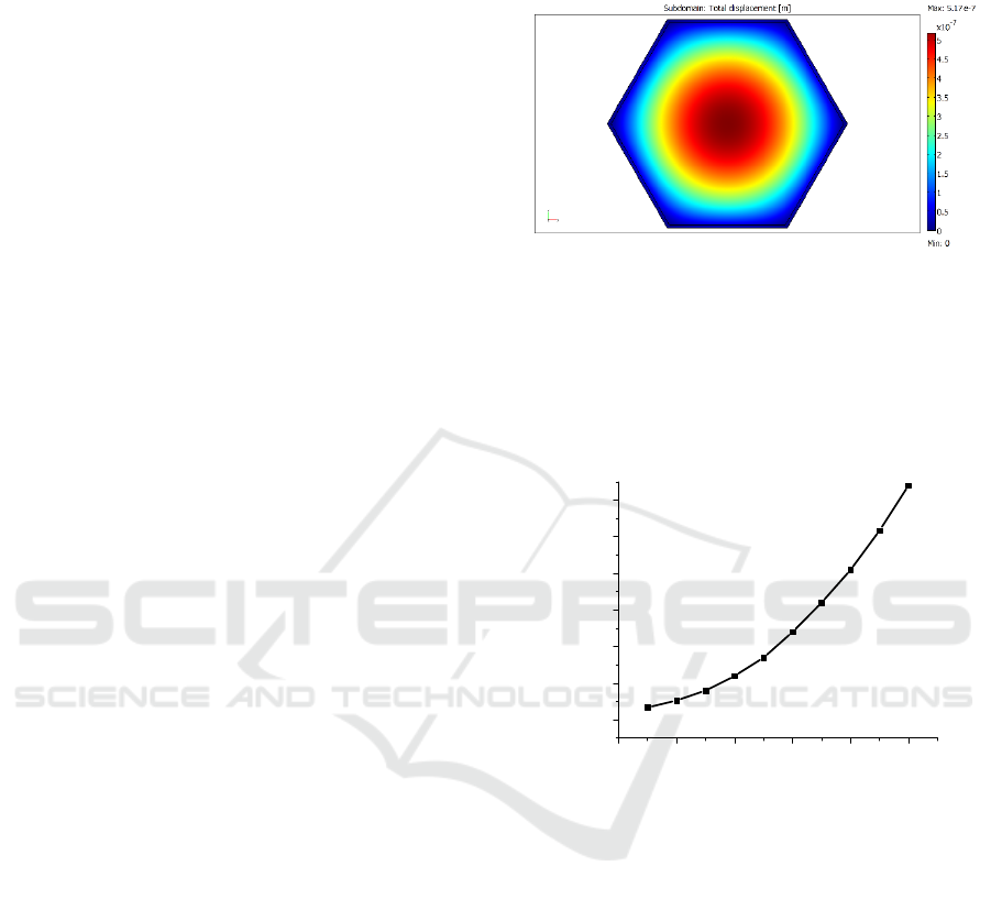
library. Figure 1 shows the FEM simulation result of
stress-induced deformation of mirror plate. The
hexagonal side length of mirror plate model is 450um.
The bowing value from the edge of plate to the centre
is 0.517um.
Figure 1: Simulation result of mirror plate deformation with
FEM in COMSOL.
Figure 2 shows the bowing value versus mirror plate
size. As shown, the bowing value increase with plate
size. The AO applications need the mirror surface
flatness no more than wavelength/5. So that we
decide to make the mirror plate size to be 250um.
0 100 200 300 400 500
0.0
0.1
0.2
0.3
0.4
0.5
0.6
The bowing value (um)
Size of plate (um)
Figure 2: Simulation result of the bowing value versus
mirror plate size.
We chose Poly1 to make electrostatic actuators. In
order to enlarge the upwards displacement of mirror
plate, lever structure is decided to be used as actuator.
The enlarge factor is equal to leverage ratio. And the
lever actuator shape is also influenced by the mirror
plate shape. As the mirror plate is hexagonal, and side
length is 250um, three actuators need to be arranged
symmetrically to achieve the mirror plate have three
degrees of freedom motion. In order to obtain the
longest lever length and the largest control electrode
area, three lever actuators are designed to cross each
other and have a special shape layout as shown in
Figure 3(a) which could improve the effective
utilization of Poly1 and reduce the print effect to
above layer. Each lever has two anchor which connect
the lever structure to the substrate and support
cantilever to serve as rotation axis of the lever. The
A High Stroke Actuator Micro-mirror Array Designed for Adaptive Optics
169
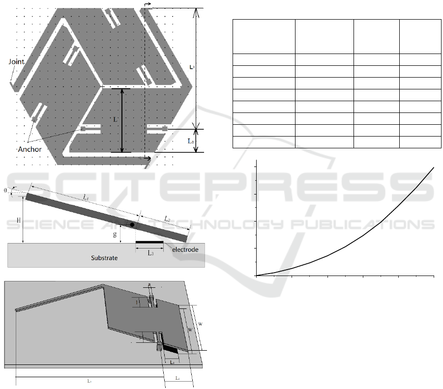
joint connects the Poly1 lever to Poly2 mirror plate.
Figure 3(b) shows the section view of lever actuator.
The lengths of two lever arms is represented by L1
and L2. While L represent the whole length of the
lever, which equals 400um. H represents the lifting
height, and g represents the gap between Poly2 and
Poly1 after the sacrificial layer is etched. L3 represent
the width of electrode fabricated by Poly0. Figure
3(c) shows the 3D model that we used to make
simulation analysis by FEM.
(a) top view of three lever actuator layout
(b) section view of lever actuator
(c) 3D model of lever actuator
Figure 3: Lever actuators structure design detail.
Table 1 shows the FEM simulation results of pull-in
voltage and maximum lifting height of levers with
different structural parameters by Comsol. The
conclusion showed that increasing resisting arm
length would improve the max lifting height while
would bring in high pull-in voltage. Higher voltage
would cause more complicated control circuit and
higher safety risk. On balance, we chose the
parameters with L1=320um, L2=80um. And Figure 4
shows the simulation results of lifting height with the
voltage applied on the electrode at the model
parameters identified above. We can draw the
conclusion that with this lever actuators, the micro-
mirror could get a large out-of-plane piston
displacement up to 8um.
Table 1: Simulation results of pull-in voltage and maximum
lifting height of levers with different structural parameters.
Length of
resisting arm
L1 (um)
Length of
power arm
L2 (um)
Pull-in
Voltage
(V)
Lifting
height
(um)
335 65 420 10.30
330 70 357 9.42
325 75 299 8.66
320 80 246 8.00
315 85 204 7.41
310 90 169 6.88
305 95 141 6.42
300 100 119 6.00
0 50 100 150 200 250
0
2
4
6
8
Lifting Height (um)
Voltage (V)
Figure 4: Simulation results of lifting height of lever with
the voltage.
3 MICROMIRROR ARRAY
APPLIED IN AO
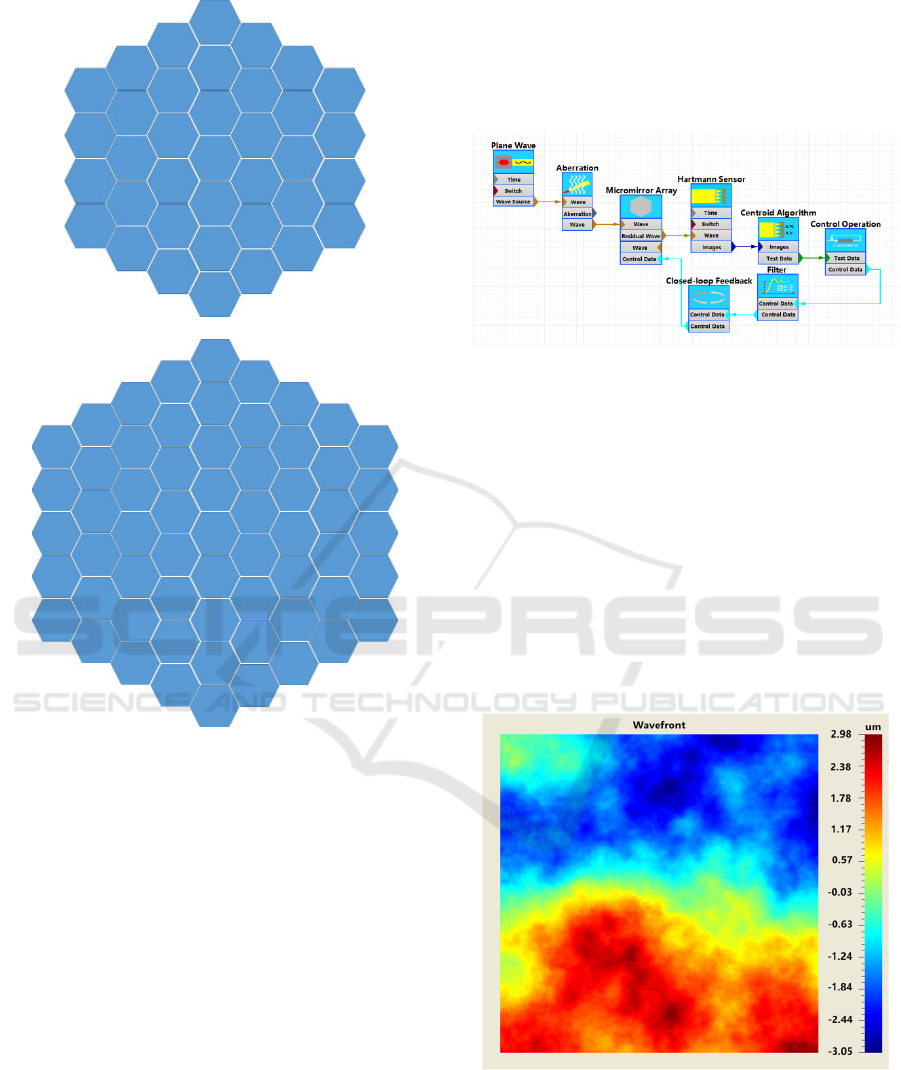
Two size of micro-mirror arrays were built with our
designed high stroke micro-mirror. As shown in
Figure 5, one array consists of 37 micro-mirrors to
form an about 1.75mm side length hexagon, while the
other consists of 61micro-mirrors to form an about
2.2mm side length hexagon. These arrays would be
use in adaptive optic (AO) system after fabrication.
We tested these arrays in an AO simulation
system. The simulation system is built in SeeLight, a
software tool for high fidelity modelling of advanced
PHOTOPTICS 2020 - 8th International Conference on Photonics, Optics and Laser Technology
170
(a) 37 micro-mirror array
(b) 61 micro-mirror array
Figure 5: Layouts of 37 micro-mirror array and 61 micro-
mirror array.
optical systems such as laser active illumination and
object detection systems which is developed by
National University of Defense Technology and
Institute of software, Chinese academy of Sciences.
The principle of the software is based on wave optics
theory with performing propagation by the angular
spectrum theory and fast Fourier transform. As each
micro-mirror in the array could make tip/tilt/piston
motion. The max piston height is 8um. We used its
characteristics to build a micro-mirror array model in
the simulation system. Figure 6 shows the models
schematic of AO simulation system. In the simulation
system, the plane wave model outputs a plane wave
beam, which transmits the aberration model and
distorts its wavefront with the aberration in medium.
The Hartmann Sensor model will measure the
distorted wavefront, and calculates the control orders
with the Centroid Algorithm model and the Control
Operation model. The Micromirror Array Model
receives the control voltage data from the Closed-
loop Feedback model and operates every micromirror
to the required height to correct the aberration
wavefront of the input beam.
Figure 6: The simulation model schematic of AO system
built in SeeLight software.
Figure 7 shows the aberration wavefront map
generated in simulation system which PV aberration
is about 6um. The size of map is transformed to be
equal to the two sizes of micromirror array, separately.
And Figure 8(a) shows the piston motion heights of
37 micromirror array, while Figure 8(b) shows that of
61 micromirror array. The RMS of corrected
residuals were 293nm and 123nm respectively.
Apparently, the micro-mirror number of the array is
larger, the AO aberration correction is better. But
larger number of micro-mirror would bring out more
complex control circuit and closed-loop algorithm.
Figure 7: The aberration wavefront map for AO to measure
and correct.
A High Stroke Actuator Micro-mirror Array Designed for Adaptive Optics
171

(a) 37 micro-mirror piston motion heights
(b) 61 micro-mirror piston motion heights
Figure 8: The aberration wavefront map for AO to measure
and correct.
4 CONCLUSIONS
In this paper, a micro-mirror with large out-of-plane
displacement actuator is designed for adaptive optics
application. The micro-mirror with three lever
actuators is designed by optimized three layers
fabrication process. Micro-mirror structure models
were built in Finite element analysis (FEA) software
Consol to get the optimum structural parameters. The
micro-mirrors were tightly arranged in a hexagonal
array to serve as a deformable mirror. An AO
simulation system was built to test the aberration
correction effect of the micro-mirror array. The
results showed that the 61 micro-mirror array was
better than 37 micro-mirror array in aberration
correction, which showed good application prospect
of this high stoke micro-mirror array in AO systems.
ACKNOWLEDGEMENTS
The main author would like to acknowledge Professor
Edmond Cretu at University of British Columbia in
Canada who provided the opportunity for me to visit
and start the research on this area in his lab.
REFERENCES
Chen W. C., Wu C. Y. and Lee C. K., 2003. Bi-directional
movable latching structure using electrothermal V-
beam actuators for optical switch application. In Proc.
IEEE/LEOS Opt. MEMS (Hawaii, USA 18-21 Aug
2003), pp 149-150.
Tsai C., H. and Tsai J., C., 2015. MEMS optical switches
and interconnects. Displays, Vol.37, P33-40.
Yan J., Kowel S. T., Cho H. J. and Ahn C. H., 2001. Real-
time full-color three-dimensional display with a
micromirror array. Optics Letters, 26, 1075-1077.
Freeman M. O., 2003. Miniature high-fidelity displays
using a biaxial MEMS scanning mirror. In Proc. SPIE
4985 56-62.
Zhang Y. H., Poonja S. and Roorda A., 2006. Adaptive
Optics Scanning Laser Ophthalmoscope using a
Microelectro-mechanical (MEMS) Deformable Mirror.
Proc. SPIE 6138, 61380Z.
Manzanera S., Helmbrecht M. A., Kempf C. J., Roorda A.,
2011. MEMS segmented-based adaptive optics
scanning laser ophthalmoscope. Biomedical Optics
Express, Vol.2, No.5, P1204-1217.
Blain Celia, 2013. Modelling MEMS deformable mirrors
for astronomical adaptive optics, University of Victoria
(Canada), Ph.D.
Morzinski K. M., Evans J. W., Severson S., Macintosh B.,
Dillon D., Gavel D., Max C. and Palmer D., 2006.
Characterizing the potential of MEMS deformable
mirrors for astronomical adaptive optics. Proc. SPIE
6272, 627221.
L. MC A., Flath M. W. Kartz, Wilks S. C., Young R. A.,
Johnson G. W. and Ruggiero A. J., 2002. Free Space
Optical Communications Utilizing MEMS Adaptive
Optics Correction. Proc. SPIE 4821, 129-138.
Li J., Chen H. Q., Yan G. P., Liu Y. and Wu P., 2005.
Improve space laser communication using adaptive
optics system based on MEMS technology. Proc. SPIE
5985, 59851R
Dagel D. J., Cowan W. D., Spahn O. B., Grossetete G. D.,
Grine A. J., Shaw M. J., Rsnick P. J. and Jokier B.,
2006. Large-stroke MEMS Deformable Mirrors for
Adaptive Optics. J. Microelectromech. Syst., 15, 572-
581.
Sun Q., He K. and Cretu E., 2010, Optimization designed
large stroke MEMS micromirror for adaptive optics.
PHOTOPTICS 2020 - 8th International Conference on Photonics, Optics and Laser Technology
172

CHINESE OPTICS LETTERS, Vol.8, No.12, P1163-
1166.
Lin P. Y., Hsieh H. T. and John Su G. D., 2011. Design and
fabrication of a large-stroke MEMS deformable mirror
for wavefront control. Journal of Optics, Volume
13, Number 5, P55404-5541.
Carter J., Cowen A., Hardy B., Mahadevan R., Stonefield
M. and Wilcenski S., 2005. PolyMUMPs Design
Handbook (Revision 11.0), MEMSCAP Inc.,
http://www.memscap.com/mumps/documents/PolyM
UMPs.DR.v11.pdf.
Zhang X. M., Chau F. S., Quan C., Lam Y. L. and Liu A.
Q., 2001. A study of the static characteristics of a
torsional micromirror. Sensors and Actuators A:
Physical, 90, 73-81.
Sun Q., Cai M., Wang N. Y., Cretu E., 2009. Mechanical
design and system-lever analysis of a novel
micromirror array. Proc. SPIE 7510, 751003
Zhang J. L., Zhang Z. X., Lee Y. C., Bright V. M. and Neff
J., 2003. Design and investigation of multi-level
digitally positioned micromirror for open-loop
controlled applications. Sensors and Actuators A:
Physical, 103, 271-283.
Chiou J. C., Kou C. F. and Lin Y. J., 2007. A micromirror
with large static rotation and vertical actuation. IEEE
Journal of Selected Topics in Quantum Electronics, 13,
297-303
A High Stroke Actuator Micro-mirror Array Designed for Adaptive Optics
173
