
Homogeneous Light Source for Surface Plasmon Resonance Imaging
Peter Hausler, Simon Jobst, Johannes Fischer, Carina Roth and Rudolf Bierl
Sensorik-ApplikationsZentrum SappZ, Ostbayerische Technische Hochschule Regensburg,
Franz-Mayer-Str. 1, Regensburg, Germany
Keywords: Surface Plasmon Resonance Spectroscopy, Sensor, SPR-imaging, Miniaturization,
Micro-opto-electro-mechanical Systems.
Abstract: We describe how to build a homogeneous light source for Surface Plasmon Resonance Imaging (SPRi) which
mainly finds its applications in pharmaceutical screening and biotechnology so far. SPR spectroscopy is a
label-free, non-destructive and highly sensitive measurement principle for detecting changes in the refractive
index in close vicinity of a gold surface. A transfer of this technology to a miniaturized sensor will broaden
the range of possible applications. Commercial SPR assays are mainly working with a small number of
sensing spots. In contrast, the SPR imaging system shown here will allow the use of an array of many sensing
spots. In combination with chemical receptors designed as an artificial nose or an electronic tongue, the
simultaneous detection of many analytes is envisioned. So far, lasers or other inhomogeneous light sources
were used to illuminate the sensing surface, which is decreasing the systems sensitivity. We show a compact
(< 60 mm), low cost, LED based light source which is providing a large area (>300mm2) homogeneous top
hat profile. The combination of a high bit-resolution camera with our new light source enables a reflectivity
based surface plasmon resonance imaging system with a high refractive index unit (RIU) resolution.
1 INTRODUCTION
Surface Plasmon Resonance (SPR) technology is
label free, non-destructive and highly sensitive
(Schasfoort, 2017). Due to these properties, SPR is an
attractive measurement principle for chemical
sensors. Nevertheless, there are some drawbacks
limiting its applications so far: most measurement
setups are designed for being used in laboratories and
therefore they are very expensive. The high
temperature sensitivity and the need of trained
personal for its operation impede reliable in-field
sensing. Miniaturized and automated systems could
overcome these problems. Motivated by these
prospects, many miniaturized systems were
developed, (Ribeiro, 2019) includes an overview on
miniaturized SPR systems. Most of these systems
suffer either from missing transportability or from
low sensitivity.
Beside reflectivity based SPR imaging (Fig.1)
many other SPR technologies have been developed to
increase sensitivity, (Wang, 2019) is a review about
the state of the art and an overview of the most
common technologies. However, these technologies
are introducing new components which are
complicating miniaturization.
In order to be able to apply reflectivity based SPR-
imaging to miniaturized sensor systems we developed
a compact, low cost light source, which is providing
a large area, homogeneous illumination.
2 SENSING PRINCIPLE
While a thin gold film is irradiated by light, typically
the entire light will be reflected (Fig. 1). However, if
the light is p-polarised and the angle of incidence is
altered, one can see a narrow dip in the intensity of
the reflected light. This dip is indicating that at this
certain angle of incidence (SPR angle) surface
plasmons are excited. The SPR angle mainly depends
on the refractive index in close proximity to the gold
film which is deposited on a coupler, usually a glass
prism. Therefore, the refractive index on one side of
the gold is constant, which means that any variations
in the chemical composition – and therefore in the
refractive index – next to the other side of the gold
film is determining the position of the SPR-angle.
Selectivity to a special molecule of interest is
Hausler, P., Jobst, S., Fischer, J., Roth, C. and Bierl, R.
Homogeneous Light Source for Surface Plasmon Resonance Imaging.
DOI: 10.5220/0009168701630167
In Proceedings of the 8th International Conference on Photonics, Optics and Laser Technology (PHOTOPTICS 2020), pages 163-167
ISBN: 978-989-758-401-5; ISSN: 2184-4364
Copyright
c
2022 by SCITEPRESS – Science and Technology Publications, Lda. All rights reserved
163
generated by a chemical functionalization of the gold
film by recognition elements. There are many
different ways on how to utilize surface plasmons
(Wang, 2019). The principle we used is reflectivity
based SPR, since it has the simplest setup. Hence it is
the most promising method for miniaturization.
Reflectivity based SPR has no moving parts, which
makes it more robust. During the design process one
fixed angle at the linear region of the SPR-reflectivity
slope is chosen for measurement. If the refractive
index of the analyte is changing, the position of the
minimum is moving and hence the reflectivity is
changing (R Fig.1).
3 SYSTEM SETUP
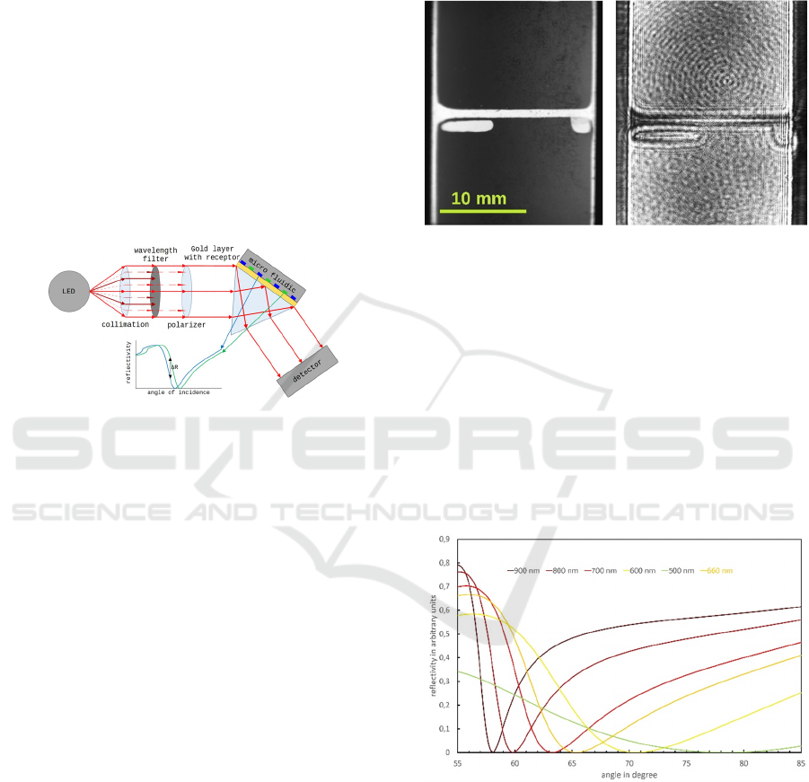
Figure 1: System-Setup, made of a LED based light source,
a gold-coated prism with receptors and a detector as well as
a 18 x 18 mm microfluidic chip, which is distributing the
analyte.
Most single or multi-channel SPR setups are using
laser light sources. For SPR-imaging, lasers are not
suitable since they are known for generating speckles
and diffraction patterns (Fig.2). Typical regions of
interest (ROI) do have a size between 50 µm and 5
mm. While having small size ROI, the noise which is
generated by the diffraction patterns is lowering the
resolution of the system dramatically. Most lasers
also have a Gaussian beam profile. If the sensing
surface is illuminated with a Gaussian beam profile a
small movement of the components will cause a
movement of the steep flank thorough the ROI and
hence a high change of the reflected signal. The
replacement of the laser by our LED based light
source overcomes this issue. LED light is very
broadband compared to laser light and it is non-
polarised. Therefore, a wavelength bandpass filter
and a polarizer were integrated into the system.
Furthermore, the beam is tailored and collimated. The
modified beam illuminates a 50 nm gold film which
is on top of a Schott F2 glass prism. The reflected
light is collected by a 2D-camera system, which
records the spatial change of the intensity of the
reflected light beam (Fig.1).
Superluminescence diodes would provide similar
characteristics to lasers but without spatial coherence
but they are excessively expensive. The high price
would impede the use of the SPR technology for
infield sensors.
Figure 2: Comparison of a LED light source left and a laser
light source right; the coherent laser light is generating
diffraction patterns due to dust particle, edges and air
bubbles.
The aim was to build a light source which is
available at a low price and which can be
miniaturized. Unstabilized lasers show mode
hopping, which would introduce noise and lower the
systems resolution. Speckles and other diffraction
patterns would also generate some noise.
Furthermore, the widening of the laser beam would
require a long optical path. Therefore, lasers are not
suitable for miniaturized systems.
Figure 3: Simulation of an SPR signal according to changes
in the excitation wavelength, the thickness of the gold layer
was fitted in every simulation to achieve a minimum
reflection; the SPR curve is getting steeper at higher
wavelength, which raises the sensitivity; simulation was
done with WinSpall software.
The SPR effect is very sensitive to wavelength
shift and its sensitivity is increasing with an
increasing wavelength (Figure 3). On the other hand,
the sensitivity of CMOS cameras is decreasing
PHOTOPTICS 2020 - 8th International Conference on Photonics, Optics and Laser Technology
164

rapidly with an increasing wavelength. Moreover, the
development of a system is much easier if the
wavelength is visible.
In order to have the system components available
for very low price at good performance we have
chosen a 660 nm LED from OSRAM (GH
CSSRM2.24). It is an important wavelength for
horticulture and is therefore readily available. In
order to be able to alter the driving current and to have
low noise at the same time, we used a Keithley
Sourcemeter as a current source for the laboratory
setup.
The beam shaping was done with a single 25 mm
diameter plastic aspheric lenses from Edmund Optics.
Depending on the desired beam characteristics, the
focal length was chosen at a range between 25 mm
and 75 mm (e.g. f40 #66-024). In order to avoid a
wavelength shift, a custom made 2 nm FWHM filter
from Chroma was used. The polarization was
controlled with a 1:9000 polarizer from Edmund
Optics (#85-919).
The prism is made of Schott F2 glass and has P4
polished surfaces to provide best performance.
By altering the position and the focal length of the
collimation lens, the divergence of the light can be
altered. If the SPR system is built with a light source
with low or no divergence a camera can be used even
without objective lenses.
The suitable camera should be chosen depending
on the demands, concerning refractive index unit
(RIU) resolution, system price and volume. The
ximea MU9PM-MH with its APTINA
MT9P031sensor is offering a 12 bit resolution at a
low price and very low volume (15 x 15 x 8 mm)
while the PCO Edge 4.2 is offering an outstanding
resolution of 16 bit. The PCO Edge with its 16 bit is
providing a high RIU resolution and the large chip
size is enabling an acquisition of a large SPR-Image
without the use of a lens. Between these two cameras,
there are many different cameras, which could be
used. Currently, a good compromise between costs,
size and bit resolution are cameras with a Sony
IMX178 sensor like the ISG Allegro.
4 RESULTS
Figure 2 shows the comparison of an LED light
source (left) and a laser light source (right). Both are
providing a “TopHat like” beam profile. In case of the
laser, a very small area at the centre of the Gaussian
beam profile was cut out. This Process is generating
diffraction pattern at the edge of the lenses which
were used to cut out the centre part. Furthermore, the
edges of the prism and microfluidics as well as air
bubbles and dust are generating diffraction patterns.
The result is a very noisy illumination which could be
sufficient for single or multi-channel measurement
with very large regions of interest (ROI) but it is
totally insufficient for high resolution SPR imaging.
Figure 4: False colour SPR image made with a laser based
light source and a Ximea CMV4000 10 bit camera; left:
diffraction patterns originating from edges, dust particles
and air bubbles are visible; right: cross-section along the
black line from the left side, the noise which is originating
from diffraction is clear to see
Figure 4 shows a SPR image which was recorded
with a laser based light source. The cross-section,
which was taken along the direction of the black line
shows that there is tremendous noise which is
lowering the RIU resolution of the SPR imaging
system. To avoid this kind of noise a LED based light
source was developed. LED’s do not have spatial
coherence, therefore they do not generate diffraction
patterns.
Figure 5: False colour SPR image, made with a LED light
source and a ISG allegro 14 bit camera; left: the SPR active
area is illuminated homogeneous, red areas are the sealing
and a air bubble; right: cross section along the the direction
of the black line, the cross section shows the SPR curve
which is originating from the divergent illumination.
Figure 5 shows a SPR image, which was recorded
with a LED based light source. The cross-section,
Homogeneous Light Source for Surface Plasmon Resonance Imaging
165

which was taken along the direction of the black line
shows the SPR curve which is originating from the
light source divergence. A LED cannot be collimated
like a laser, therefore a small divergence will always
remain. Unlike Figure 1, which shows perfectly
collimated light from a laser, a LED based light
source is generating light rays, which are not perfectly
parallel. Therefore, the angle of incidence is shifting
slightly from one side to the other side of the sensing
area. This divergence can be utilized to monitor every
sensing spot at its most sensitive angle. If the SPR
system does not monitor only one receptor but many
different, e.g. 100 spots, it is very likely that every
spot has a different refractive index. This implies that
only one spot is monitored at its most sensitive SPR
angle if a non-divergent light source is used, all the
others are falling behind their possibilities. However,
if a divergent light source is used, the angle of
incidence is splayed and every receptor can be placed
at its most sensitive angle of incidence.
While collimating a laser is very simple,
homogenizing an LED is very complex. One could
use an opal glass but this option would cause
tremendous power losses on the one hand and
focusing on infinity would not lead to a homogeneous
beam shape on the other hand. Therefore, we
developed another technique to create a
homogeneous beam area. We have found an
empirical equation which relates focal length of the
lens, distance of the lens to the desired homogeneous
surface and lens placement:
⋅exp
With
: Placement relative to focal plane
: Distance of lens to homogeneous surface
: Focal length of lens
Parameter Value
2.5698
1.9311
37.265
0.0383
Figure 6: Placement of optical components, the 1mm
aperture in front of the opal glass has been omitted in the
schematic.
The SPR sensing area is inclined according to the
beam direction (Figure 1) therefore the beam has to
be homogeneous in a wider area along the beam
direction and not only in one plane. The
is the
distance between the lens and the centre of the
homogeneous area.
This equation is valid for focus length in the range
of f 20 to f 120 and for a lens – homogeneous region
distance of 40 mm up to 110 mm. The equation
should be understood as an approximation, which is
helping to build a homogeneous light source, which
is based on a non-homogeneous LED chip. Since
most LED’s do have a lens on top, we placed an opal
glass in front of the LED to determine the equation.
However, we did the same procedure without opal
glass and it lead to the same homogeneous results.
The equation without opal glass has different
parameters because of the added lens on top of the
LED.
Placing the SPR prism, the lens and the light
source according to this equation will lead to a
homogeneous illumination of the prism surface. If the
light is s-polarized the whole surface is iluminated
homogeneously. If the light is p-polarized a gradient
like it is shown in Figure 5 appears. The reduction of
the reflectivity is caused by the generation of surface
plasmons and the gradient of the reduction originates
from the remaining divergence of the light beam.
Combining this technology with a low noise current
source creates a light source, which enables high
resolution SPR imaging.
PHOTOPTICS 2020 - 8th International Conference on Photonics, Optics and Laser Technology
166
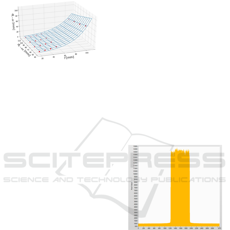
Figure 7: Plot of the equation, as a function of focal length
and distance between lens and homogeneous surface; red
dots are measurements conducted with the described setup.
Figure 7 shows the plot of the equation. While
utilizing our method one has to deal with four
parameters, which are divergence, width of the
homogeneous area perpendicular to the beam
direction, width of the homogeneous region along the
beam direction and distance between LED and
homogeneous region.
One could use a lens with low f-value to achieve
a short distance between H-region and LED, while
doing so, the divergence will increase and the
spreading of the SPR-angle will be higher. On the
other hand, one could use a high f-value to achieve a
low divergence, this would increase the distance
between H-region and LED. Therefore, one has to
choose the best option for every task.
5 CONCLUSIONS
SPR-imaging was lacking of cheap, large area and
homogeneous light sources. We described how to
build a cheap, LED based light source, which is
providing a homogeneous illumination over the entire
sensing surface. The beam profile is homogeneous
over a wide range along the beam direction and not
only in one single plane. An empirical equation shows
how to place lens and light source in relation to the
sensitive area. We were able to reproduce the
experiment many times and it is in use every day.
However, the equation is not very exact and should
therefore be understood as an approximation. The
empirical equation is lacking a theoretical equation,
thus more investigation has to be done in this field.
However, the concept can already be used and it
enables high-resolution SPR-imaging on large
surfaces. The light source was used for high RIU
resolution experiments. Combined with a PCO Edge
SCMOS camera we achieved resolutions in the 10
-7
RIU range. The results are currently under
publication.
ACKNOWLEDGEMENTS
This work is funded by the Bavarian Ministry of
Economic Affairs, Energy and Technology
(ESB051/006).
REFERENCES
Schasfoort R., 2017. Handbook of surface plasmon
resonance, Royal Society of Chemistry, London.
Ribeiro P., Raposo M., 2019. Optics, Photonics and Laser
Technology 2018, Springer, Heidelberg.
Wang D., 2019. Recent Advances in Surface Plasmon
Resonance Imaging Sensors. Sensors, 19(6), S. 1266.
doi:10.3390/s19061266
APPENDIX
Figure 8: Cross section along the direction of the black line
of figure 5 with s-polarized light.
Homogeneous Light Source for Surface Plasmon Resonance Imaging
167
