
Cascaded Tunable Optical Delay Line based on a Racetrack
Resonator with Tunable Coupling and Stable Wavelength
Solomon Getachew Hailu
1
and San-Liang Lee
2
1
Graduate Institute of Electro-Optical Engineering, National Taiwan University of Science and Technology,
No. 43, Sec. 4, Keelung Rd., Taipei 10607, Taiwan
2
Department of Electronic and Computer Engineering, National Taiwan University of Science and Technology,
No. 43, Sec. 4, Keelung Rd., Taipei 10607, Taiwan
Keywords: Group Delay, Racetrack Resonator, Tunable Optical Delay Line, Power Transmission, Thermal Tuning.
Abstract: We propose a novel integrated optical delay line based on a cascaded racetrack resonator with tunable coupler
by push-pull operation of each stage to stabilize the resonant wavelength. The thermal tuning effect and the
photonic characteristics of the whole integrated device is simulated to verify the characteristics of the tunable
ODLs. The tuning of hundreds of ps is achievable with a very compact device and very small power
consumption. The two-stage configuration can allow for reaching larger delay time or a wider bandwidth
depending on the operation condition.
1 INTRODUCTION
Integrated optical delay lines (ODLs) are key
components in photonic circuits for many
applications. The optical delay line can be realized
exploiting either a single stage or multiple cascaded
stages. The use of two cascaded stages allow to
increase either the delay tunability or the bandwidth
of device compared to a single-stage ODL (Melati &
Melloni, 2018). They can be found in numerous
applications, such as optical signal processing and
buffering in optical networks, beamforming and
filtering in microwave photonic systems, bio-medical
sensing, and 3D light scanning and ranging (Zhou, et
al., 2018) (Melati, et al., 2018) (Han, et al., 2013)
(Cardenas, et al., 2010).
Integrated on-chip ODLs exhibt multiple benefits
correlated to bulk optics or fiber-based ODLs, such as
the reduced cost, size, weight, and power
consumption (Zhuang, et al., 2013) (Melati, &
Melloni, 2018) (Melloni, et al., 2010) (Liu, et al.,
2018) (Balbas, et al., 2007). The integrated optical
delay lines have been illustrating for a variety of
utilization (Pegios, et al., 2018) (Park, et al., 2008)
(Capmany, & Novak, 2007) (Hyeon, et al., 2015).
Various integration platforms can be utilized to
construct ODLs. There are several trade-offs in the
delay line performances, like bandwidth and
maximum delay, integration density and waveguide
propagation loss needs to be acknowledging before
picking the proper platforms. Silicon photonics
platform based on the silicon-on-insulator (SOI) is
regarded as one of the most promising technologies
for large-scale high-density photonic integration
because of its large index contrast, small bending
radius and the use of compatible fabrication facilities
in semiconductor foundries (Melloni, et al., 2010)
(Xie, et al., 2007). There are several semiconductor
foundries and research institutes providing the multi-
project-wafer (MPW) process for SOI-based photonic
integration, which can reduce the research and
development cost for realizing tunable ODLs.
Therefore, our design is based on the SOI platforms.
There are two common used approaches to tune
the SOI-based ODLs: tuning with thermal heating or
carrier-induced effects. Both tuning mechanisms
change the refractive index of the waveguide and then
change the phase. Thermal tuning is usually the
choice for its simple device structure and low optical
loss as long as the tuning speed is not the major
concern. Tunable optical delay lines based on ring
resonators have been demonstrated by several groups
(Bogaerts, et al., 2012) (Poon, et al., 2004) (Katti, &
Prince, 2018) (Xie, et al., 2014). Most of the designs
are for optical signal processing or buffering. In these
applications, the critical requirements include large
enough true delay, wide bandwidth, and low higher-
Hailu, S. and Lee, S.
Cascaded Tunable Optical Delay Line based on a Racetrack Resonator with Tunable Coupling and Stable Wavelength.
DOI: 10.5220/0009164901570162
In Proceedings of the 8th International Conference on Photonics, Optics and Laser Technology (PHOTOPTICS 2020), pages 157-162
ISBN: 978-989-758-401-5; ISSN: 2184-4364
Copyright
c
2022 by SCITEPRESS – Science and Technology Publications, Lda. All rights reserved
157
order phase variations that will lead to dispersion and
signal distortion. Therefore, multiple stages of ring
resonators are employed to achieve the desired delay
with large bandwidth and low distortion (Cardenas, et
al., 2010).
In this work, we design an optical delay line based
on two-stage racetrack resonator equipped with
tuning heaters. The design aims at the applications for
optical and bio-medical sensing where the optical
signal usually narrow linewidth.
We explain that with the proper control design, the
novel architecture doubles the group delay tunability
range compared to a single-stage racetrack resonator
ODL and achieves a limited delay-bandwidth product
(DBP). The ODL design demonstrated in this paper
can achieve a true delay ranging from tens of
picoseconds to hundreds of picoseconds at a stable
wavelength.
2 CASCADED INTEGRATED
OPTICAL DELAY LINE
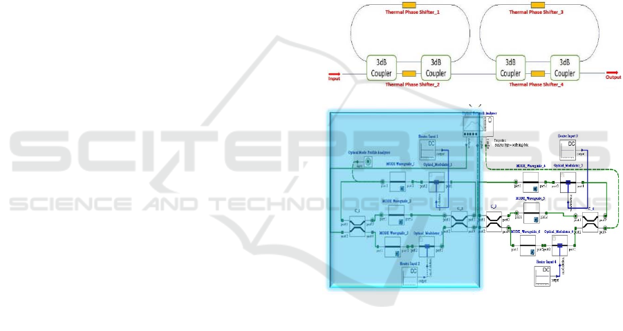
Figure 1 (a) shows the schematic of the 2-stage ODL
where each stage is a tunable racetrack resonator with
a tunable coupler. The tunable coupler is a symmetric
Mach-Zehnder interferometer (MZI) with one of the
two arms equipped with a thermal heater based phase
shifter to tune the output ratio of the MZI. The peak
delay occurs at the resonance condition of the
racetrack resonator. The peak delay depends on the
coupling ratio of the MZI output. In general, as the
peak delay increases, the insertion loss of the ODL
rises and the wavelength bandwidth decreases. On the
same time, the peak wavelength where the peak delay
occurs moves with the coupling ratio. In order to
stabilize the peak wavelength in the application field
of optical sensing, the two phase shifters of each stage
is operated in push-pull mode. That is, as one phase
shifter is heating up, the other one will be cooling
down. The peak wavelength of the two stage can be
aligned to double the peak group delay or shifted
slightly to have a greater bandwidth.
To verify the operation characteristics of the
proposed 2-stage ODL, the simulation using the
Lumerical Solutions’ Photonic Design Tools
conducted here (Lumerical INTERCONNECT,
2019). The used to realize the two-stage integrated
ODL, which details as shown in Figure 1. The block-
diagrams component blocks used in the Lumerical
Interconnect is depicted in Figure 1(b). The device
architecture is constructed with six Lumerical MODE
waveguides, four thermal modulators, four 3-dB
couplers, four DC source components, and an optical
network analyzer. In each component block, we
import the exact file that comes from the MODE
simulation. We import the saved data from MODE
simulations into MODE waveguide and modulator
components. The change of effective index as a
function of input power of Heater 1, and Heater 3 can
be deposited into the "Optical Modulator 1", and
"Optical Modulator 3" respectively, and the change of
effective index as a function of input power of Heater
2, and Heater 4 can be loaded into "Optical Modulator
2", and "Optical Modulator 4" respectively. In each
component of MODE waveguide, we imported the
proper file of TE mode thermal waveguide profiles.
The response of the devices was measured through
the Optical Network Analyzer that permits
characterizing the power transmission spectrum and
the group delay spectrum.
(a)
(b)
Figure 1: (a) Schematic of 2-stage tunable delay lines, (b)
Lumerical INTERCONNECT blocks for the two cascaded
identical stages ODL based on racetrack resonator and MZI.
The box with blue shaded part includes the schematic of a
single stage delay line.
3 TWO STAGE INTEGRATED
OPTICAL DELAY LINE
SIMULATION RESULTS
Figure 2 shows the group delay, power transmission,
and wavelength at the resonant condition as a function
of the input power of Heater 4 when the input power
of Heater 1 and Heater 3 is fixed at 0 mW. It
corresponds to the case that only the coupling
PHOTOPTICS 2020 - 8th International Conference on Photonics, Optics and Laser Technology
158
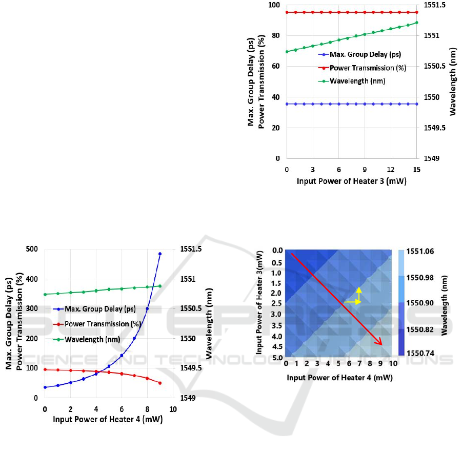
coefficient of the ODL is tuned. By tuning the input
power of Heater 4, from 0 to 7mW, the group delay,
measured at the resonant peak varies from 35.62 ps to
201.43 ps, while the corresponding power
transmission efficiency at the transmission dip in the
spectrum, can be kept above 80% over the tuning
range. However, the peak wavelength shifts from
1550.74 nm to 1550.85 nm during tuning. That is, the
wavelength drifts at a rate of 0.0016 nm/mW
regarding the input power of Heater 4. This
wavelength drift will appear in a change in the group
delay for a fixed wavelength. Also, Figure 3 shows
the results for tuning the racetrack loop phase with
Heater 3 by fixing the input power of Heater 2 and
Heater 4 at 0 mW. During the tuning of Heater 3, the
peak group delay and power transmission are almost
constant, but the wavelength varies linearly with a
slope of 0.031 nm/mW. Hence, Heater 3 can be used
to correct the resonant wavelength without affecting
the group delay and power transmission.
Figure 2: Simulation of the group delay, power
transmission, and wavelength at the resonant peak versus
the input power of Heater 4 when the other heater is at 0
mW.
Figure 4 shows the contour plot of the wavelength
of the proposed ODL as a function of the input power
of the two heaters. The contour plot will be used to
illustrate how to tune the group delay and keep the
peak wavelength intact. Figure 4 shows the tuning of
the peak wavelength versus the power to heater 3 and
4, as indicated by the red arrows in Figure 4. The
triangular background pattern shows in Figure 4 is the
wavelength due to the push pull operation of the
heaters tuning. This figure shows particularly one of
the peaks between the several peaks caused by the
ring resonance.
Figure 3: Simulation of the group delay, power
transmission, and wavelength at the resonant peak versus
the input power of Heater 3 when the other heater is at 0
mW.
Figure 4: Contour plot of wavelength as a function of the
input power of heaters.
Figure 5 shows that the peak group delay can be
continuously tuned by simply changing the input
power to Heater 4 while it remains fixed in the tuning
of Heater 3. From Figures 2 & 3, the wavelength drift
rate is different for tuning Heater 4 and Heater 3,
respectively. Moreover, the tuning of Heater 3 and
Heater 4, the shift of the wavelength is in the same
direction (longer wavelength). To retain the
wavelength in tuning the group delay, the two heaters
require to be operated at the push-pull mode. That is,
the heater input power to heater 3, must be decreasing
as the input power to heater 4, increases.
As designated by the yellow arrows in Figure 4
and 5 as an example, the input power of Heater 4 is
increased to increase the group delay, then the input
power to Heater 3 needs to be decreased to keep the
same peak wavelength.
Cascaded Tunable Optical Delay Line based on a Racetrack Resonator with Tunable Coupling and Stable Wavelength
159
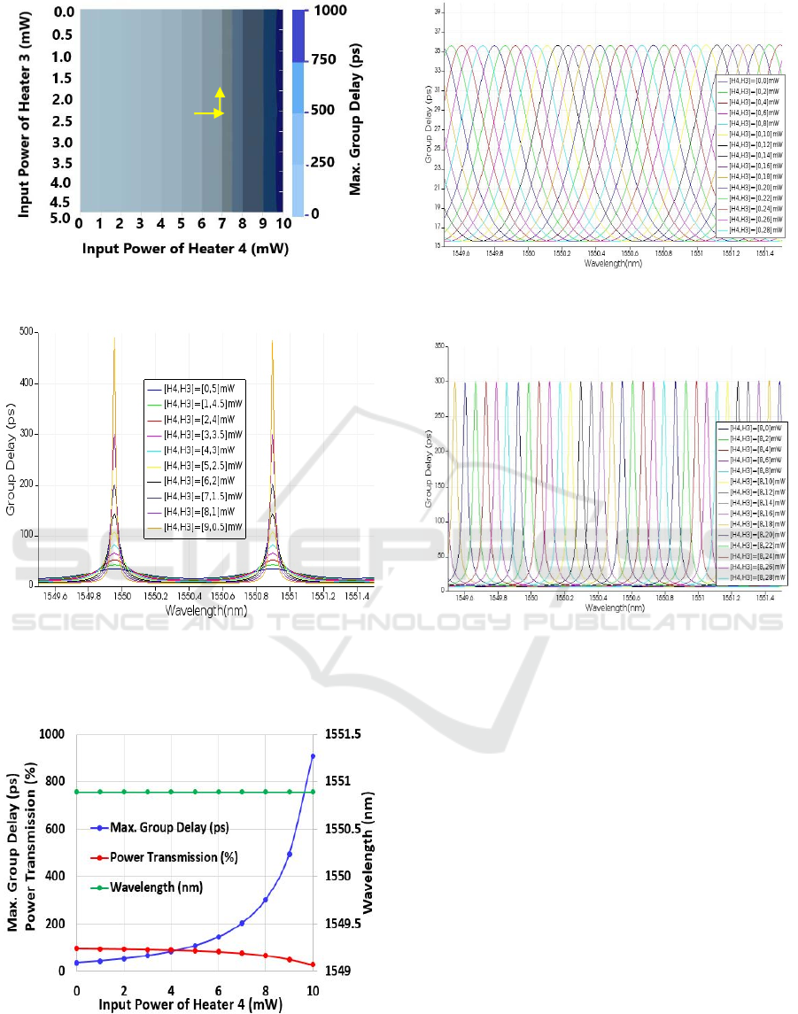
Figure 5: Contour plot of peak group delay as a function of
the input power of heaters.
Figure 6: Group delay as a function of the wavelength for
[(H4, H3) = (0,5), (1,4.5), (2,4), (3,3.5), (4,3), (5,2.5), (6,2),
(7,1.5), (8,1), (9,0.5)] mW, where H3 and H4 indicate the
power to Heater 3 and 4, respectively.
Figure 7: Peak group delay, power transmission, and
wavelength as function of the input power of heater 4.
Figure 8: Group delay as a function of the wavelength for
[(H4, H3) = (0, 0-28)] mW.
Figure 9: Group delay as a function of the wavelength for
[(H4, H3) = (8, 0-28)] mW.
Figure 6 depicts the tuning spectrum for the push-
pull operation. Since the wavelength drift rate for
tuning Heater 3 is about double of that for tuning
Heater 4, the input power for Heater 4 and Heater 3 is
of a step of 1 mW and 0.5 mW, respectively, for the
spectra shown in Figure 7. During group delay tuning,
the resonant wavelength is almost fixed. The
summary of the group delay, power transmission, and
wavelength by tuning the two heaters together at the
push-pull mode is as shown in Figure 7. The
wavelength keeps constant while the group delay is
tuned by more than one order of magnitude.
Figures 8 and 9 show that the peak group delay can
be tuned over one free spectral range (FSR) by using
less than 30 mW of the Heater 3 power when the input
power of Heater 4 is 0 and 8 mW for different delay
time. Due to the periodic delay-time characteristics,
Figures 8 and 9 indicates that the proposed two-stage
tunable delay lines can be tuned to track the
wavelength of the input light sources over a wide
wavelength range and provide the needed group delay.
PHOTOPTICS 2020 - 8th International Conference on Photonics, Optics and Laser Technology
160

4 CONCLUSIONS
We present here a novel way of tuning the group
delay of a two-stage optical delay line by operating
the thermal heater at push-pull mode. The peak group
delay and resonant peak wavelength can be tuned
almost independently. The group delay is tuned by the
heater in one arm of the balanced MZI coupler to vary
the effective coupling coefficient to the resonator. On
the other hand, the thermal tuning on the racetrack
loop can correct the wavelength drift without
affecting the group delay. The simulation using the
practical device structure of a semiconductor foundry
is pursued to demonstrate the group-delay tuning
characteristics of such a racetrack-resonator.
The targeted applications for such tunable optical
delay lines are for optical sensing and/or bio-medical
sensing, where the light source usually has very
narrow linewidth. We demonstrate the tuning of
group delay to nearly 40 ps while fixing the resonant
wavelength by adjusting the heating power of Heater
3. The maximum group delay can be achieved by
tuning the coupling coefficient to have an even
sharper resonant peak with a tradeoff on the
transmission power. The tuning of hundreds of
picosecond is achievable with a very compact device
and very small power consumption. The use of two
cascaded identical stages with the described control
scheme allows to double both the tunability range of
the group delay compared to a single-stage ODL.
ACKNOWLEDGEMENTS
This research was supported by the Ministry of Science and
Technology, Taiwan, under Grant MOST 108-2622-E-011-
CC1.
REFERENCES
Melati, D., & Melloni, A. (2018). On-chip continuously
tunable optical delay line based on cascaded Mach-
Zehnder interferometer. In proceedings of the Optical
Fiber Communication Conference, OSA, San Diego,
California, USA.
Zhou, L., Wang, X., Lu, L., Chen, J., (2018). Integrated
optical delay lines. COL. Rev. 16, pp. 101301:1-
101301:16.
Melati, D., Waqas, A., Mushtaq, Z., & Melloni, A., (2018).
Wideband integrated optical delay line based on a
continuously tunable Mach-Zehnder interferometer.
IEEE J. Sel. Topics Quantum Electron. 24, pp.1-8.
Han, X., Wang, L., Zou, P., Wang, Y., Zhang, S., Gu, Y.,
Wang, J., Jian, X., & Zhao, M., (2013). A Tunable
Optical Waveguide Ring Resonator for Microwave
Photonic Filtering. In Proceedings of the IEEE
International Topical Meeting on MWP, Alexandria,
VA, USA, 28-31.
Cardenas, J., Foster, M. A., Sherwood-Droz, N., Poitras,
C.B., Lira, H L., Zhang, B., Gaeta, A. L., Khurgin, J.B.,
Morton, P., & Lipson, M., (2010). Wide-bandwidth
continuously tunable optical delay line using silicon
microring resonators. Opt. Express. 18, pp. 26525–
26534.
Zhuang, L., Hoekman, M., Beeker, W., Leinse, A.,
Heideman, R., van Dijk, P., & Roeloffzen, C., (2013).
Novel low-loss waveguide delay lines using Vernier
ring resonators for on-chip multi-λ microwave photonic
signal processors. Laser Photon. Rev. 7, pp. 994–1002.
Melloni, A., Canciamilla, A., Ferrari, C., Morichetti, F.,
O’Faolain, L., Krauss, T.F., de La Rue, R., Samarelli,
A., & Sorel, M., (2010) Tunable delay lines in silicon
photonics: Coupled resonators and photonic crystals, a
comparison. IEEE Photonics J. 2, pp. 181–194.
Liu, Y., Whichman, A. R., Isaac, B., Kalkavage, J., Adles,
E.J., Clark, T.R., & Klamkin, J., (2018). Ultra-low-loss
silicon nitride optical beamforming network for
wideband wireless applications. IEEE J. Sel. Topics
Quantum Electron. 24, pp. 1-10.
Balbas, E. M., Pandraud, G., & French, P. J., (2007)
Thermo-Optical Delay Line for Optical Coherence
Tomography. Proc. of SPIE 6717, pp. 671704:1-
671704:9
Pegios, M. M., Alexzndris, G. M.., Terzenidis, N., Cherchi,
M., Harjanne, M., Aalto, T., Miliou, A., Pleros, N., &
Vyrsokinos, K., (2018). On-Chip SOI Delay Line Bank
for Optical Buffers and Time Slot Interchangers. IEEE
Photonics Technology Letters. 30, pp. 31-34.
Park, H., Mack, J. P., Blumenthal, D. J., & Bowers, J. E.,
(2008). An integrated recirculating optical buffer. Opt.
Express. 16, pp. 11124-11131.
Capmany, J., & Novak, D., (2007). Microwave photonics
combines two worlds. Nature Photonics. 1, pp. 319–330.
Xia, F., Sekaric, L., & Vlasov, Y., (2007). Ultra compact
optical buffers on a silicon chip. Nature Photonics. 1,
pp. 65–71.
Hyeon, M. G., Kim, H. J., Kim, B. M., & Eom, T. J., (2015).
Spectral Domain Optical Coherence Tomography with
Balanced Detection Using Single Line-Scan Camera
and Optical Delay Line. Optics Express. 23, pp. 23079-
23091.
Bogaerts, W., De, H. P., van Vaerenbergh, T., De, V. K.,
Kumar, S. S., Claes, T., Dumon, P., Bienstman, P., van
Thourhout, D., & Baets, R., (2012). Silicon microring
resonators. Laser & amp Photonics Rev. 6, pp. 47–73.
Takahashi, H., Carlsson. P., Nishimura, K., & Usami, M.,
(2004). Analysis of Negative Group Delay Response of
All-Pass Ring Resonator with Mach-Zehnder
Interferometer IEEE Photonics Technology Letters. 16,
pp. 2063-2065.
Green, W. M., Lee, R. K., deRose, G. A., Scherer, A.,
Yariv, A., (2005). Hybrid InGaAsP-InP Mach-Zehnder
Racetrack Resonator for Thermo-Optic Switching and
Coupling Control. Optic Express. 13, pp. 1651-1659.
Cascaded Tunable Optical Delay Line based on a Racetrack Resonator with Tunable Coupling and Stable Wavelength
161

Poon, J. K., Scheuer, J., Mookherjea, S., Paloczi, G. T.,
Huang, Y., & Yariv, A., (2004). Matrix analysis of
microring coupled-resonator optical waveguides.
Optics Express. 12, pp. 90-103.
Katti, R., & Prince, S., (2018). Photonic Delay Lines Based
on Silicon coupled Resonator Optical Waveguide
Structures. Silicon. 10, pp. 2793-2800.
Xie, J., Zhou, L., Zou, Z., Wang, J., Li, X., & Chen, J.,
(2014). Continuously tunable reflective-type optical
delay lines using microring resonators. Optics Express.
22, pp.817-823.
Lumerical Solutions’ Inc.Innovative Photonic Design
Tools, URL:http://www.lumerical.com (accessed on 14
March 2019).
PHOTOPTICS 2020 - 8th International Conference on Photonics, Optics and Laser Technology
162
