
Business Processes with Pre-designed Flexibility for the Control-flow
Thomas Bauer
a
Hochschule Neu-Ulm, University of Applied Sciences, Wileystr. 1, 89231 Neu-Ulm, Germany
Keywords: Process Modelling, Process Execution, Process Engine, Pre-modelled Flexibility, Flexibility by Design.
Abstract: In order to avoid limitations for end users, run-time deviations from the pre-defined business process have to
be allowed at process-aware information systems (PAIS). Predictable flexibility shall be pre-designed already
at build-time. The advantage, compared to completely dynamic modifications at run-time, is that this signifi-
cantly reduces the effort for the end users necessary to trigger a deviation. Furthermore, this increases process
safety since, for instance, it can be pre-defined which users are allowed to perform which modifications. In
this paper we present the corresponding requirements for the control-flow perspective. Thereby, the main
focus is to discuss which information has to be pre-designed at build-time in each case. Furthermore, examples
from practice are presented in order to illustrate the necessity of the requirements.
1 INTRODUCTION
Business processes (BP) are an important topic in sci-
entific literature and practice. Often, only the aspects
modelling, optimization, and simulation of BP are re-
spected. But also the automatic control of BP by pro-
cess management systems (PMS) offers many ad-
vantages. Their usage results in process-aware infor-
mation systems (PAIS) (Reichert and Weber 2012)
that guarantee that the process is executed exactly as
defined at build-time (process reliability). Further-
more, non-productive actions of end users are no
longer necessary; e.g. searching the right function of
the application or the data required in the current pro-
cess step. PAIS perform such actions automatically.
However, they have disadvantages as well: Some us-
ers have problems with the reduced freedom that re-
sults from the active process control by the PMS. Ad-
ditionally, in exceptional cases, execution orders of
process activities, which would be advantageous for
the business, are not possible because of the modelled
process template. In order to avoid such disad-
vantages, there must exist the flexibility to vary from
the rigidly designed BP
(Redding et al. 2009); (Scho-
nenberg et al. 2007); (Dadam et al. 2011).
A special case of flexibility are predictable devi-
ations, which are pre-designed at build-time with the
goal to apply them later on at run-time of the process
a
https://orcid.org/0000-0001-8360-8430
instances (Pre-Designed Flexibility (Kumar and Na-
rasipuram 2006), Flexibility by Design (Schonenberg
et al. 2007)). In scientific literature, however, only
this categorization is mentioned. Details of the corre-
sponding requirements and realization approaches
were not in the focus of existing research.
The project CoPMoF (Controllable Pre-Modelled
Flexibility) addresses this aspect. The goal is to im-
prove the flexibility of PMS by deviations, which are
not defined arbitrary (i.e. completely dynamic) by the
end users. Instead, already at build-time, it was de-
fined which predictable flexibility is required at run-
time. This allows the BP-designer and the BP-owner
(the responsible person) to evaluate the consequences
of these possible deviations. In addition, process reli-
ability is guaranteed because only approved devia-
tions may occur and only users with the required
rights are allowed to trigger deviations.
But the main advantage is the reduced effort for
the end users to trigger a deviation, compared to de-
fining a dynamic modification (eventually it would be
even too complicated to do this completely dynami-
cally). Assume that a telephone enquiry fails for a
specific customer. As solution, an activity “enquiry
by mail” could by inserted dynamically into the BP.
Then, the user of the PAIS would have to define all
the specifications described in the following (the bet-
ter solution is to pre-design these specifications at
build-time only once): The location of the additional
Bauer, T.
Business Processes with Pre-designed Flexibility for the Control-flow.
DOI: 10.5220/0009161606310642
In Proceedings of the 22nd International Conference on Enterprise Information Systems (ICEIS 2020) - Volume 2, pages 631-642
ISBN: 978-989-758-423-7
Copyright
c
2020 by SCITEPRESS – Science and Technology Publications, Lda. All rights reserved
631

activity within the control-flow has to be defined (i.e.
the preceding and successive activities). Addition-
ally, the data-flow has to be specified; i.e., the map-
ping of the input and output parameters of the activity
to the variables of the BP. For instance, the field
Street of the input parameter Address shall get its con-
tent from the attribute CustomerStreet of the BP-var-
iable CustomerAddress. Furthermore, an appropriate
actor assignment has to be defined; e.g. “role = credit-
approver and department = x”, whereat x is read from
the attribute ExecutingUnit of the BP-variable
CreditApplication.
With dynamic modifications (Reichert and Weber
2012) new activities can be inserted into a process in-
stance, and they can be deleted and moved. This is
necessary to realize not predictable changes. As ex-
plained above, completely dynamic modifications are
not suited well for predictable exceptional situations,
since they cause much effort for the users at each
change. It is better to pre-design eventually required
flexibility only once during build-time.
Scientific literature only defines the category pre-
designed flexibility, but there exists no work concern-
ing details. That means, it is known that (additionally
to the building blocks offered by common BP model-
ling languages; e.g. BPMN) further functionality is
required to model flexible and understandable pro-
cess templates (Laue and Kirchner 2017). Such func-
tionality, however, is not examined in a detailed and
comprehensive way until now. Therefore, no answer
exists to the following research question: At which
scenarios (i.e. requirements) it is advantageous to pre-
design flexibility of a BP at build-time, and which in-
formation shall be provided for this purpose?
The approach developed in the project CoPMoF
has the following properties:
The identified requirements shall cover as many
scenarios as possible. However, completeness
cannot be reached because of the research design.
To identify a large number of requirements, de-
spite multiple BP are analysed with respect to
their flexibility requirements. The author knows
these BP because of his long-term work in indus-
try and research. In addition, generally known BP
and processes described in scientific literature
(e.g. credit application) were respected.
As a result of the presented approach, the BP tem-
plates are “enriched” with pre-designed flexibil-
ity. Thereby, they shall stay well-understandable
for BP-designers and “normal users”. Naturally,
this is necessary for semantic process models (the
business view), but also for technical models (pro-
cess implementation); e.g., to enable users to de-
tect the errors of a process model.
Despite this simplicity, the building blocks for
pre-designed flexibility must have a clear execu-
tion semantics, since a vague modelling technique
would not allow automatic execution of process
instances by a process engine.
Triggering a flexible deviation at run-time shall
cause only very little effort for the end users.
The following topics are covered by this paper: BP of
different domains are presented. The scenarios of pre-
dictable flexibility are explained based on these case
studies. Thereby, several requirements and their vari-
ants are explained, in order to present the scenarios
exhaustively. Thus, the validity of the requirements is
shown with examples from practice. In this paper
solely the control-flow perspective (Jablonski 1997)
is respected; for other process perspectives see (Bauer
2018b, 2019b) .The development of detailed realiza-
tion concepts (e.g. execution semantics for a process
engine, cf. (Bauer 2018a, 2019a)), a prototypical re-
alization, and case studies based on this prototype will
be part of future work.
The following section introduces several terms
and explains the basic principles of PAIS. In addition,
the challenges are demonstrated at an example pro-
cess from practice. Section 3 presents the require-
ments and corresponding practical examples. Section
4 discusses related work. The paper concludes with a
summary and an outlook in Section 5.
2 BASICS AND CHALLENGES
Section 2.1 describes basics of PMS. In Section 2.2,
some problem statements for pre-designed flexibility
are explained at an example scenario from practice.
2.1 Business Process Management
PMS have of a build-time and a run-time component.
During build-time, a process template is designed that
defines the BP. Hereto, a process graph that contains
activities as nodes is modelled. Their execution order
is defined by edges and conditions. At run-time, pro-
cess instances are created based on this process tem-
plate. A process engine controls the execution of mul-
tiple process instances. When an activity instance (of-
ten named short: activity) becomes executable it in-
serts a work item into the worklists of its potential ac-
tors. One of these users picks the work item and per-
forms this activity (instance). Activity execution is
often performed by filling a form.
The control-flow perspective of a BP defines the
execution order with a process graph (cf. Figure 1).
Its nodes are activities that represent human tasks and
ICEIS 2020 - 22nd International Conference on Enterprise Information Systems
632
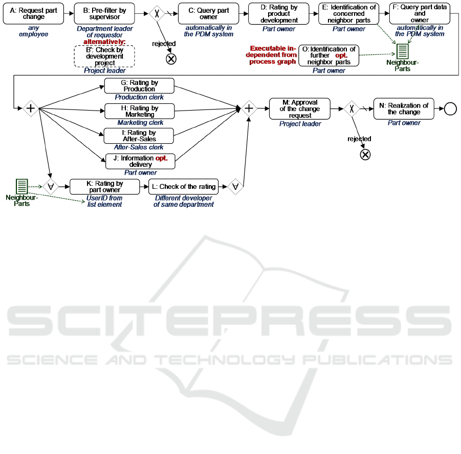
Figure 1: Change Management Process (CMP) for Product Modifications.
automatically executed program code (e.g. service
calls). Additionally, the it contains gateways (Split-
and Join-Nodes). (Russell and Hofstede 2006) de-
scribe many control-flow patterns. Commercial PMS
typically offer Split- and Join-Nodes with XOR- (one
branch is chosen based on a rule), OR- (several
branches), and AND-Semantics (all branches are ex-
ecuted). Loops are typically supported as well.
Branches and loops are a simple kind of pre-designed
flexibility, since the set of executed activities and
their execution order may differ for the process in-
stances. In addition, some PMS enable the definition
of a variable number of identical parallel branches.
This number must be determined at least when start-
ing this “Multi-Instance-Parallelism”. This corre-
sponds to the control-flow pattern “Multiple In-
stances with a priori Run-Time Knowledge” (Russell
and Hofstede 2006).
2.2 Pre-designed Flexibility
In this subsection, an example BP from practice is
presented in order to demonstrate the need for pre-de-
signed flexibility. As already explained, completely
dynamic modifications are not in the focus of this pa-
per. Instead, predicable exceptional cases are in-
spected. In such cases, an appropriate behaviour can
be pre-designed already at build-time.
The simplified Change Management Process
(CMP) depicted in Figure 1 is used to request product
changes in the automotive domain. The notation is
similar to BPMN 2.0 (but extended). Any user may
request a change of a vehicle part (e.g. the shape of
the engine bonnet) with Act. A. The execution of a
whole CMP-instance causes much effort. Therefore,
it can be stopped with Act. B resp. B' by a manager.
Act. C determines the owner of the concerned part
with a query to the product data management (PDM)
system automatically. In Act. D this owner rates the
effort and the benefits of the change from the view-
point of the development domain. Afterwards, in Act.
E he identifies neighbour parts (e.g. car wing, radia-
tor) that must be changed because of the modified
shape of the engine bonnet as well. Act. F queries the
corresponding part details and part owners and stores
these data in the list NeighbourParts.
With Act. G to I, clerks of several domains are
rating (in parallel) whether the change can be real-
ized. Additionally, they estimate the resulting costs.
With Act. J, the part owner may provide additional
information to these clerks (for instance, if this was
requested by phone). The rating from the viewpoint
of the neighbour parts happens in Act. K by the re-
spective part owner. This activity is instantiated mul-
tiple times (once for each neighbour part). The same
applies to the check of the rating by another developer
in Act. L. Act. M decides on the approval of the
change request. The parts may be changed in Act. N.
The execution of the CMP requires flexibility at
several points: Act. B' was designed as alternative to
Act. B. B' is used if Act. B is not appropriate in this
case; e.g., since the department leader does not have
sufficient technical competences for the decision.
Act. J was marked as optional (flag opt.). This means
that it appears in the worklist of the part owner with a
corresponding label. He has to decide, whether he
needs to deliver additional information, or whether he
Business Processes with Pre-designed Flexibility for the Control-flow
633
wants to omit this activity. The Act. K and L are in-
cluded within a Multi-Instance-Parallelism. That
means, the -Split creates a number of branches that
corresponds to the length of the list NeighbourParts.
This list was filled by Act. E and F. But it may also
be extended afterwards by Act. O. It is independent
of the process graph. Therefore, it may be executed at
an arbitrary point in time. However, its execution
does only make sense before the Multi-Instance-Par-
allelism is finished (i.e. before the -Join). Later on,
additional neighbour parts cannot be respected by ad-
ditional instances of Act. K and L any more.
3 PATTERNS FOR
PRE-DESIGNED FLEXIBILITY
This section explains the approach of CoPMoF; i.e.,
what shall be pre-designed at build-time to achieve
flexibility at run-time without causing much effort for
the end users. The necessity of these requirements is
demonstrated with examples from practice. In this pa-
per, only the perspective control-flow (CF) is re-
spected. For other process perspectives, because of
the limited space, we refer to (Bauer 2018b, 2019b).
Some of the presented scenarios have similarities
with well-known control-flow patterns (Russell and
Hofstede 2006). In the following they are discussed
from the viewpoint of pre-designing flexibility.
3.1 Optional Activities
The end users decide, whether an optional activity
shall be executed, or whether it is not relevant for this
process instance. For this purpose, the activity is dis-
played in their worklists. Then, the users are able to
start this activity. The worklist item, however, con-
tains a label that indicates that this activity is optional.
Furthermore, there is a possibility to omit the activity;
e.g., by using a corresponding button included in this
worklist item. Additionally, a pre-modelled hint may
be displayed, that explains when the activity shall be
executed and when it shall be omitted. An optional
activity may also be a composed activity, with the ef-
fect that a whole sub-process is omitted.
At build-time, it must be possible to pre-define
that an activity shall be optional (cf. Act. J in Figure
1); e.g. by setting a flag. In some cases, an optional
activity shall be skipped “automatically”; i.e., without
any user omitting it actively (see below: CF-1b und
c). Such a behaviour must be definable as well.
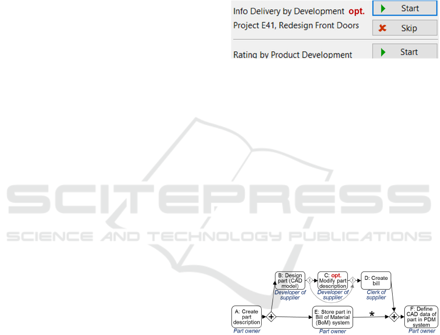
CF-1a: The regular case for optional activities is that
they are executed. To omit an optional activity, the
user has to perform an action actively (e.g. use the
button Skip in Figure 2). At this example, at the CMP
depicted in Figure 1, Act. J is offered to the part
owner until he performs the activity or he decides to
omit it. This is meaningful since the provided infor-
mation is used by the concurrently executed Act. G to
I as well as by the successive Act. M. Therefore,
providing information with Act. J can be necessary
even after completion of Act. G to I.
Figure 2: Worklist with an optional Activity.
Other scenarios require a different behaviour:
CF-1b: In the process depicted in Figure 3, the origi-
nal part description is created in Act. A. With the op-
tional Act. C, however, it can be modified (typically
slightly) if this becomes necessary because of the de-
sign decisions made in Act. B. The part description is
transmitted to the BoM system by Act. E. Act. E,
however, does not wait for the execution or omission
of Act. C, since the BoM data are urgently required
by other BP and delays would not be acceptable. If
the lower branch is completed (i.e. it reached the
AND-Join) the execution of Act. C is not meaningful
anymore (since its output data is only used by Act. E).
Therefore, Act. C is omitted by the process engine au-
tomatically. This behaviour shall be definable for Act.
C at build-time.
Figure 3: Development of a Part by a Supplier.
CF-1c: If we modify the example of Figure 3, a dif-
ferent behaviour becomes necessary: Assume that af-
ter Act. E (at the *) there exist further activities X and
Y. Then, Act. C shall not only be omitted when the
lower branch reaches the AND-Join (since Act. X and
Y do not use the output data of Act. C). Instead, it
must be definable that Act. C is omitted automatically
as soon as Act. E completes. That means, Act. E has
the role of a “milestone” for Act. C.
To summarize, for optional activities it must be
possible to define at build-time which behaviour (CF-
1a to c) shall be used. In case of CF-1c, it must be
possible to define which activity acts as milestone.
ICEIS 2020 - 22nd International Conference on Enterprise Information Systems
634

It is not possible to realize optional activities with
normal XOR-Nodes
1
(as sketched with grey colour in
Figure 3), since in case of CF-1a a different (resp. no)
user interaction would result: The branching decision
would be made already at the XOR-Split based on
rules and values of BP-variables. In case of its omis-
sion, Act. C would never appear in the worklists of
the potential actors. In the other case, it would not be
possible to omit it anymore. The problem is, that the
branching decision is made too early. CF-1b and c
cannot be realized this way as well, for the same rea-
son: The decision whether Act. C shall be offered to
the users would be made at the XOR-Split. This is too
early if the completion of the lower branch (CF-1b)
resp. Act. E (CF-1c) occurs later. In all cases, a work-
around with XOR-Nodes does not result in the de-
sired behaviour; i.e., optional activities must be of-
fered as separate construct for the control-flow of BP.
3.2 Alternative Activities
The necessity of alternative activities was already
mentioned for the CMP in Section 2.2: If the depart-
ment leader is not capable to execute Act. B, a differ-
ent Act. B' is executed instead (e.g., with a different
form and performed by a different person).
At alternative activities the PMS behaves as fol-
lows: The standard Act. X is inserted into the work-
lists of all potential actors. Additionally, a label is dis-
played, that indicates that an alternative Act. Y exists,
and a pre-defined hint explains when this alternative
shall be used. Now, the user is able to switch to the
alternative activity by performing an active action;
e.g., by using a button (except for CF-2d, see below).
The BP-designer defines at build-time for each al-
ternative activity, which of the following types shall
be used; i.e., when and how the decision for the alter-
native activity is made.
CF-2a: The user makes this decision before reserving
(resp. starting) the regular activity X. This is the nor-
mal and simplest case.
CF-2b: Even after the start of Act. X (i.e. during its
execution), the user may decide to switch to the alter-
native Act. Y. Then, the regular Act. X is aborted au-
tomatically and the alternative Act. Y is inserted into
the worklists.
CF-2c: The user may realize later on that the alterna-
tive activity would have been the better choice. Then,
the alternative Act. Y is executed additionally to the
1
A realization would be possible with a XOR-Split with
“Deferred Choice” Semantics (Russell & Hofstede, 2006).
This type of XOR, however, is typically not supported by
commercial PMS. As alternative, in BPMN, a two-way
regular Act. X. This makes sense, for instance, for an
Act. X that captures data and an alternative Act. Y
that captures more or different data. If someone real-
izes, at a successive activity of the BP, that the output
data of the alternative Act. Y is required, it is executed
additionally (i.e. delayed) in order to complement the
originally captured process data.
CF-2d: The alternative activity is selected by the pro-
cess engine automatically if the execution of the reg-
ular activity fails. This may be caused by a failed ser-
vice call of an automatically executed activity. At a
manually executed activity (human tasks) the check
of post-conditions may indicate that it has failed (e.g.
missing or inconsistent output data).
At build-time, it must be possible to define who
has the right to switch to the alternative activity. Of-
ten, a (potential) actor of the regular activity has to
make this decision. But it shall be possible to restrict
this set of persons; e.g., to (especially competent) per-
sons which possess a special role.
If the alternative activity is composed, a whole
sub-process is selected instead of a single activity.
Then, not only one actor is concerned by this deci-
sion, but all actors of sub-process activities. There-
fore, it is possible that the decision has to be made by
an especially responsible person (e.g. project leader)
who may not be an actor of the regular activity.
Naturally, it is possible that, for one regular activ-
ity, several alternative activities are pre-modelled.
Then, the user may select the most appropriate one.
Alternative activities, again, cannot be realized
with (normal) XOR-Nodes. Similar as for CF-1, the
decision would be made too early; i.e., before the reg-
ular activity was inserted into the worklists.
3.3 Jumps within the Process Graph
CF-3a: Forward Jumps. Assume a travel applica-
tion process where the approval happens after several
evaluations and cost ratings which may take a long
time. At a travel application for a near-term appoint-
ment, as exception, it may be necessary to jump di-
rectly to the approval and omit some of these activi-
ties. Otherwise, an important appointment would be
missed resulting in economic loss.
The simplest case is that the jump happens before
its source activity (i.e. the starting point of the jump)
is started. If the source activity was already started, it
may be aborted before jumping. At build-time, it must
event-based XOR-Split may be modelled in combination
with intermediate throw and catch events. Defining such
a sophisticated BP graph, however, may overwhelm “nor-
mal” BP designers.
Business Processes with Pre-designed Flexibility for the Control-flow
635

be definable whether a jump is allowed with this ac-
tivity as source, whether it shall be aborted (automat-
ically), and which are the allowed target activities.
Additionally, it has to be modelled, who is allowed to
trigger a jump; e.g., the current actor of the source ac-
tivity or the process owner.
For the missed activities (between the source and
the target node) it has to be defined, whether they
shall be caught up. Often, they will be omitted finally.
It may be necessary, however, to execute a missed ac-
tivity later on. For instance, one of the cost ratings
may be necessary (after the approval) for the calcula-
tion of the travel expenses. It must be definable at
build-time, therefore, whether an activity has to be
caught up and, furthermore, whether this is allowed
anytime or whether this must happen before the start
of a specific successive activity.
To keep clarity, a process modelling tool shall be
able to hide all edges that represent pre-designed
jumps. When they are displayed, they shall be distin-
guishable from the regular control-flow. Addition-
ally, it must be possible to define whole regions as
allowed source resp. target of a jump (cf. the grey
edges and blocks in Figure 4).
Realizing jumps with normal XOR-Splits is
hardly meaningful. As discussed at CF-1, the condi-
tions of XOR-Splits are evaluated too early. In addi-
tion, many XOR-Gateways and edges would be re-
quired, which make the process graph confusing. In
the travel application process, a separate XOR-Split
in front of all evaluations and cost ratings would be
necessary to enable all required forward jumps.
CF-3b: Backward Jumps. Assume that, during the
execution of Act. E to L of the CMP (Figure 1), a user
detects that incorrect data were captured in Act. D.
Therefore, the request cannot be approved (Act. M).
Instead, the process shall jump back to Act. D in order
to repeat it. Afterwards, this part of the process is ex-
ecuted again (with correct data).
In this scenario, there exist many possible source
activities (Act. E to L) for the jump. As explained
above, it is no good idea to insert a XOR-Split after
each of them. Instead, one source and one target re-
gion shall be modelled. Additionally, it has to be de-
fined, who has the right to trigger this jump.
After performing a backward jump, the process
graph is traversed forward again. Therefore, for each
activity it has to be defined (at build-time) how the
original results (output data) shall be handled. There
exist three possibilities and it depends on the nature
of the activity, which one is suited best.
1. Discard: The original results are discarded and
the activity is executed “normally” as at its first
execution.
2. Control: The activity is executed again, but the
original output data are kept. The user can in-
spect these data in a pre-filled form and may cor-
rect it, if necessary.
3. Keep: The activity is not executed again und its
output data are kept unchanged.
The CMP is used to explain, why all possibilities are
meaningful: Assume that Act. G to I are completed,
when jumping back from Act. L to Act. D. Discard
(1.) is used for Act. I. Its original output data are ir-
relevant (therefore discarded) since a changed part
causes different purchase and installation costs at a
repair. Control (2.) was selected for Act. G. The re-
sults of Act. G may be influenced seldom by changed
development data. Therefore, they have to be con-
trolled and modified sometimes. Such a modification
becomes necessary, for instance, if the changed part
data results in a more difficult assembly procedure.
Keep (3.) was specified for Act. H. It is not necessary
to execute this activity again (after the backward
jump) since changed development details are not rel-
evant for marketing. The variants 2 and 3 have the
advantage that time and effort may be saved at the re-
peated execution of the activity.
In some cases, it is necessary that the original ex-
ecution of an activity is compensated when jumping
back. Assume an order process and a backward jump
with a target before the activity “place order at sup-
plier”. Then, the order shall be cancelled or the sup-
plier shall be informed that this order must be sus-
pended (since it will be changed). For this purpose, a
compensation activity is modelled. In principle, this
is a normal activity, but it is connected with the back-
ward jump; i.e., it does not belong to the regular con-
trol-flow.
CF-3c: Jumps and Parallelism. At jumps into resp.
out of a parallelism, some additional problems occur.
Again, as sketched in Figure 4, the source and target
regions are defined at build-time (the same applies the
already described aspects; e.g. user rights). Because
of the parallelism, activities of different branches
build the source resp. target region of the jump. In
Figure 4a, for instance, possible target activities are
Act. C and D in the upper branch, Act. F and G in the
middle branch, and Act. I in the lower branch. When
triggering a jump, the user must specify one activity
of each branch as target.
Forward Jump: At the forward jump depicted in
Figure 4a, target nodes are required for 3 branches.
The user may specify, for instance, the Act. C, G, and
I for this purpose. In order to reduce the effort for the
user, it shall be possible to pre-design a default node
as target for each branch.
ICEIS 2020 - 22nd International Conference on Enterprise Information Systems
636

Figure 4: Parallelism with a) Forward b) Backward Jumps.
With respect to catching up or skipping the activ-
ities between the source and the target of the jump,
again, there exist the possibilities described for CF-
3a.
Backward Jump: Assume that in Figure 4b currently
the Act. G, I, and K have to be performed; the execu-
tion of Act. I and K was already started (by another
user). Then, the actor of Act. G triggers a backward
jump. At build-time, it was defined for each activity
how it shall behave at a backward jump. There exist
the following possibilities:
1. Abort (no Start, no Complete): An already
started activity shall be aborted (automatically).
For instance, the running Act. I is aborted since
its results would be discarded (cf. CF-3b: Dis-
card) at the repeated execution (after the back-
ward jump) anyway. In this branch, no further
activities are started (i.e. Act. J).
2. Complete (no Start): An already started activity
can be completed, but it must not be started
(newly). Assume, the already started Act. K has
the type Control (CF-3b). It can be completed,
to avoid the loss of the already performed work.
If Complete was specified for the successive
Act. L as well, it is not started. This makes sense
since until now, Act. L was not executed by a
user; i.e., no effort is lost.
3. Start&Complete: Now assume that Act. K and L
of the lower branch have this type. Then, after
completion of Act. K, the Act. L may be exe-
cuted as well. This is meaningful if their output
data are used later on (CF-3b: Keep). Then,
much time is available for the execution of these
activities, till the other branches reach the AND-
Join after the backward jump. The execution of
a branch may continue until an activity of type
Abort or Complete is reached.
As explained, this parameter may be used for the po-
tential source activities of the jump and for their suc-
cessors. Furthermore, it may be meaningful to use the
parameter for backward jumps without parallelism as
well.
In combination with Control (CF-3b) all pre-
sented parameter values are meaningful. The BP-de-
signer chooses between fast process execution
(Start&Complete: no delays caused by waiting) and
reduced effort for the users (Abort: no work is dis-
carded). The type Complete is a compromise where
already performed work is preserved but future work
may be eventually discarded.
3.4 Multi-Instance-Parallelism
An example for this building block was already pre-
sented in Section 2.2. In the CMP depicted in Figure
1, a part shall be changed. This may affect neighbour
parts since its shape may change. A list of these
neighbour parts is determined by Act. E. The number
of instances required for Act. K and L corresponds to
the length of this list and each activity instance has
different input data and actors.
CF-4a: The easiest case is that, when starting (-
Split) the Multi-Instance-Parallelism at run-time, it is
known how many parallel branches (instances of Act.
K and L) are required. This number does not change
later on. This correspond to the control-flow pattern
“Multiple Instances with a priori Run-Time
Knowledge” (Russell and Hofstede 2006).
CF-4b: With Act. O it is possible to append addi-
tional neighbour parts to the list NeighbourParts.
Therefore, additional branches are required. They re-
sult in further instances of Act. K and L and can be
created until all existing branches of the Multi-In-
stance-Parallelism have finished (i.e. all reached the
-Join). This corresponds to the pattern “without a
priori Run-Time Knowledge” (Russell and Hofstede
2006).
CF-4c: As an extension, a user-defined rule is used to
specify whether additional branches may be created
anymore. One type of rules is that this is only allowed
until a milestone in one of the multi-instance branches
is reached: For example, new branches cannot be cre-
ated anymore if the first rating by the part owner (Act.
K) has completed. This rating was not yet checked by
a colleague (Act. L); i.e., the branch has not finished
(cf. CF-4b). The execution of Act. K was based on the
original list NeighbourParts and an extended list may
result in a different rating. Therefore, it is prohibited
that this list is changed subsequently. A different type
of rules defines a milestone in a parallel branch out-
side the Multi-Instance-Parallelism: For instance, if
the production clerk has made his rating (Act. G)
based on the current list NeighbourParts, it is not al-
lowed to change this list anymore. Therefore, no new
branches may be created later on.
Business Processes with Pre-designed Flexibility for the Control-flow
637

At build-time it is pre-designed, which type of
Multi-Instance-Parallelism shall be used as well as
the rule in case of CF-4c. Furthermore, it is defined
which users have the right to create additional
branches at run-time. In the given scenario this may
be realized by the actor assignment of Act. O.
3.5 Activities Independent from the
Process Graph
CF5: There may exist activities in a BP that are of-
fered to the users additionally; i.e. they are not part of
the process graph. A user can decide to execute such
an activity if this is necessary in the current situation.
For instance, in the CMP (Figure 1), it may be recog-
nized at any point in time, that a neighbour part was
forgotten in Act. E. Therefore, it becomes necessary
to execute the process graph independent (additional)
Act. O. It complements the list NeighbourParts, what
results in an additional branch of the Multi-Instance-
Parallelism (cf. CF-4). Such a process graph inde-
pendent activity may be started by a user with an en-
try of his program menu or a special button of his user
interface. Another possibility is to offer this function
as optional activity (cf. CF-1) in the worklist of the
user during the execution of the whole process in-
stance.
At build-time, process graph independent activi-
ties are specified completely (like normal activities)
inclusive an actor assignment, the mapping of in-
put/output parameters to BP-variables (e.g. list
NeighbourParts), etc. At run-time, their usage is sim-
ilar to normal activities. Therefore, the effort for the
users is much smaller (cf. Section 1) than inserting an
additional activity dynamically (Reichert and Dadam,
1998).
For each process graph independent activity, it
has to be defined, whether it can be executed multiple
times. In addition, a pre-defined process region may
specify, when it is allowed to start this activity. At the
CMP, Act. O may be started as often as needed, but
only before the Multi-Instance-Parallelism has com-
pleted (cf. CF-4b).
As workaround, these requirements can be real-
ized with a parallel branch that contains the optional
Act. O (embedded in a loop to allow its multiple exe-
cution). This parallelism surrounds the whole process
region where Act. O may be started; i.e., from Act. F
to the -Join. If multiple process graph independent
activities with different process regions are required,
this results in a very confusing process graph.
3.6 Start-End-Dependencies between
Activities
The control-flow patterns presented in (Russell and
Hofstede 2006) enable many execution orders. These
patterns, however, only respect the order of whole ac-
tivities; e.g., Act. A must be completed before Act. B
can be started. This can be extended by respecting the
start and the end events of an activity separately. This
results in additionally (explicitly allowed) execution
orders and, therefore, increased flexibility.
There exist four possibilities to define execution
orders (the first one corresponds to a normal se-
quence):
CF-6a: EndBeforeStart End of Act. A must be be-
fore start of Act. B
CF-6b: StartBeforeStart Start of Act. A must be be-
fore start of Act. B
CF-6c: EndBeforeEnd End of Act. A must be before
end of Act. B
CF-6d: StartBeforeEnd Start of Act. A must be be-
fore end of Act. B
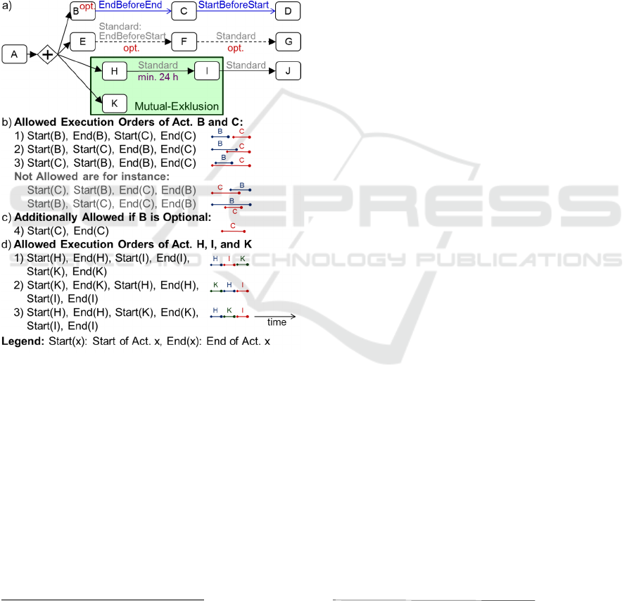
To give an example, the type EndBeforeEnd (CF-
6c) is depicted in Figure 5a for Act. B and C. The Act.
B (clean vehicle) must be completed before the Act.
C (deliver vehicle to customer) is finished. It is not
possible to clean the vehicle afterwards. But, consid-
ering this restriction, it is allowed to execute the ac-
tivities concurrently; e.g., the vehicle is cleaned dur-
ing a transportation break. The possible execution or-
ders of Act. B and C are sketched in Figure 5b.
The type StartBeforeStart is required in the fol-
lowing example (cf. Figure 5a): Act. C (the vehicle
delivery) must start before Act. D (inform customer
about upcoming delivery) starts. If the customer is in-
formed earlier, the risk of a misinformation is too
high. Before the start of the delivery, the transporta-
tion is cancelled often; e.g., because the truck is not
available or broken.
In combination with these types of dependencies,
again, optional activities (cf. CF-1) may occur. The
Act. B (clean vehicle) may be omitted if the vehicle
is already clean. This results in the additionally al-
lowed execution order depicted in Figure 5c.
CF-6e (Optional Dependencies): As extension,
start-end-dependencies may be marked as optional
(dotted edges to Act. F and to Act. G in Figure 5a). It
is desired that such a dependency is respected, but this
is not absolutely necessary. The PMS creates worklist
entries for Act. E, and additionally, entries for Act. F
and G, but with a remark that starting is not desired
yet. The user, however, can decide to execute these
activities despite.
ICEIS 2020 - 22nd International Conference on Enterprise Information Systems
638
The necessity of optional dependencies is ex-
plained with an example from a hospital: After a spe-
cific diagnosis (Act. A), typically an electrocardio-
gram (ECG) is made (Act. E), then an X-ray (Act. F),
and finally a magnetic resonance tomography (MRT)
imaging (Act. G). If one of the corresponding exami-
nation facilities is not available or overburdened,
however, it may be deviated from this standard order:
The worklists of the users contain the Act. E, F, and
G, with Act. F and Act. G marked as “not yet de-
sired”. If the ECG machine is currently not available,
the patient is directly sent to the X-ray. The radiolog-
ical assistant is able to execute Act. F without any
problems.
Figure 5: Process with Start-End-Dependencies.
CF-6f (Time Intervals): It may be necessary that
minimal and maximal time intervals are met between
activities. Assume that in Figure 5a, a part is hardened
in Act. H. Then, it has to cool for 24 hours before it
can be painted (Act. I). Therefore, Act. I shall appear
in the user worklists only after these 24 hours have
elapsed. Such time intervals are specified in the pro-
cess model and have to be guaranteed by the process
engine. Time intervals may refer to the start and the
end event of activities.
2
The search was performed with the following terms, all in
combination with business process: flexibility by design,
pre-designed flexibility, flexibility build-time, flexibility
CF-6g (Mutual-Exclusion): This is depicted in Fig-
ure 5a for the Act. H, I, and K. Only one of these ac-
tivities may be executed at any point in time. The
other activities must be executed completely before
or completely after it (cf. Critical Section and Inter-
leaved Routing in (Russell and Hofstede 2006)). A
part is hardened first (Act. H) and painted afterwards
(Act. I). Then, a bill is created (Act. J). In parallel, the
part is controlled by the customer (Act. K). The Act.
H, I, and K are performed at different locations and
they require to possess the part (physically). There-
fore, their execution cannot overlap in time. This can
be modelled with a region of mutual-exclusion. It de-
fines that no contained activity can be started while
another one is running. In the given example, this re-
sults in one of the execution orders sketched in Figure
5d. Since Act. J is not included in the mutual-exclu-
sion, its execution may overlap with Act. K.
4 RELATED WORK
Different types of flexibility for BP are presented in
(Kumar and Narasipuram 2006). The approach of
CoPMoF corresponds to the category “Pre-Designed
Flexibility”. (Schonenberg et al. 2007) details the cat-
egories resulting in the categories “Flexibility by De-
sign” and “Flexibility by Underspecification”. (Re-
gev et al. 2006) defines categories of dynamic modi-
fications and schema evolution. (Dadam et al. 2011)
distinguishes flexibility at build-time and flexibility
at run-time. The meaning of the first one, however, is
that changed process templates shall become execut-
able as soon as possible using appropriate verifica-
tions and tests. All these papers do not discuss re-
quirements for pre-designed flexibility as presented
for CoPMoF.
The result of the literature review
2
was that, until
now, it was hardly examined what shall be pre-de-
signed at build-time in order to reach much flexibility
and low effort for the users at run-time. That means,
there does not exist scientific work that explicitly
concerns pre-designing of flexibility. Instead, flexi-
bility papers in the BP domain (Reichert and Weber
2012) handles topic as dynamic modifications (e.g.
ADEPT
flex
(Reichert and Dadam 1998), Breeze
(Sadiq et al. 2000), Wasa (Weske 2001), Spade
(Bandinelli et al. 1993)), schema evolution and prop-
agation to running process instances (e.g. ADEPT2
(Rinderle 2004), Breeze (Sadiq et al. 2000),
control flow. Furthermore, Reichert and Weber (2012) as
“overview book for flexibility in BP” was examined with
respect to hints to relevant approaches.
Business Processes with Pre-designed Flexibility for the Control-flow
639

MOKASSIN (Joeris and Herzog 1998), TRAM
(Kradolfer and Geppert 1999), WASA2 (Weske
1998), WIDE (Casati et al. 1998)), or handling of BP
variants (e.g. (La Rosa et al. 2009), (Schobbens et al.
2006), ADOM (Reinhartz-Berger et al. 2010), C-
YAWL (Gottschalk 2009), Provop (Reichert et al.
2015)). Therefore, in the remaining section, ap-
proaches are described that handle topics similar to
pre-designing flexibility in a wider sense. Addition-
ally, approaches are discussed that can be used to re-
alize some of the presented requirements.
An approach to pre-design special cases is excep-
tion handling based on events and exception handlers
(Lerner et al. 2010); (Reichert and Weber 2012). For
single activities or whole process regions, an event is
modelled. If it occurs at run-time (throw) an excep-
tion handler is executed (catch). This is similar to a
try-catch-block in programming languages and well
suited to handle technical errors; e.g., the crash of an
activity program. It may also be used to handle busi-
ness exceptions during process execution; e.g., alter-
native activities (CF-2) may be modelled (Lerner et
al. 2010), (Reichert and Weber 2012). Embedding
events and exception handlers into the process model,
however, results in a more complex process graph. It
may be too complicated for many BP-designer and
business users since they typically do not possess the
required IT background. Events and exception han-
dlers, however, may be used as workaround to map
the presented requirements (automatically) to an ex-
isting BP language (e.g. BPMN) and a corresponding
PMS.
(Reichert et al. 2003) describes how pre-modelled
jumps can be mapped to regular building blocks of
the ADEPT meta model at run-time. This addresses
the requirements CF-3a and b (forward and backward
jumps), but without parallelism.
Complex control-flow patterns offer a special
type of flexibility. (Reichert and Weber 2012) de-
scribes some patterns that enable many execution or-
ders and, therefore, offer pre-designed flexibility. In
addition to designing a BP, the aspects execution se-
mantics and verification (i.e. checking correctness of
a process model) are respected. But the requirements
that concern flexibility by design are not presented
comprehensively. (Russell and Hofstede 2006) de-
scribes even more control-flow patterns. This work,
however, does not focus on requirements for pre-de-
signing flexibility as well. (Weber et al. 2008) pre-
sents “Pattern of predefined change” to pre-model
that specific decisions shall only be made at run-time.
This includes Multi-Instance-Parallelism (cf. CF-4)
In (Klingemann 2000), additional Quality of Ser-
vice Goals (e.g. process execution time, costs) are de-
fined for BP. The PMS automatically deviates from
the standard process, if necessary, to reach these goals
even in exceptional cases. For this purpose, three
types of “flexible elements” are offered: alternative
activities (cf. CF-2), non-vital (i.e. optional) activities
(CF-1), and optional execution orders (they shall be
respected but also parallel execution is allowed; this
is similar to CF-6e).
The approach of (Redding et al. 2009) enables a
special kind of pre-designed flexibility. The process
execution order is defined by the processing order of
business objects (data). Different types of business
objects interact and their signals define the execution
order. Optional signals enable flexibility, since they
are triggered by a user. These “dynamic signal types”
enable pre-designed flexibility and, therefore, cover
some of the requirements of CoPMoF: An activity
may be “delegated” to a different (alternative) activity
type (cf. CF-2). Furthermore, it is possible to create
additional (optional) activity instances and sub-pro-
cesses (CF-1). Their type is pre-modelled and this ac-
tion is only allowed in pre-defined process states (cf.
process regions).
The goal of the approach of CoPMoF is to reach
high flexibility, however, a process structure shall ex-
ist; i.e., a process graph has to be modelled. The ap-
proaches described in the following have a different
goal: a much higher degree of flexibility. At the ap-
proach of (Mangan and Shazia 2002) only process
fragments are (pre-)modelled, not the whole BP. Con-
straints (i.e. rules, conditions) define, which frag-
ments shall be used, which dependencies exists be-
tween the fragments, and when a process instance is
finished. Based on this information, at run-time, the
user is able to create process instances (manually) that
fulfil his needs. Case Handling (Aalst et al. 2005) is
an approach for knowledge intensive BP, with the fo-
cus on data. The state of a process instance results
from the content of its data objects. It determines the
activities that are currently executable; i.e., the con-
trol-flow is not modelled explicitly. The users decide
(autonomously) to execute, skip, or repeat activities.
There exist several constraint-based approaches
(e.g. (Montali 2010), (Pesic et al. 2007), (Sadiq et al.
2001), Freeflow (Dourish et al. 1996), Tucupi
(Wainer et al. 2004)) and rule-/goal-based approaches
(Burmeister et al. 2006). They all have in common
that no control-flow is modelled as graph. Instead,
constraints (rules) are defined which restrict the set of
allowed execution orders. That means, all executions
orders are allowed that do not violate a constraint. By
ICEIS 2020 - 22nd International Conference on Enterprise Information Systems
640

defining only a few constraints, a large number of ex-
ecution orders can be modelled. Therefore, it is pos-
sible to reach high flexibility with little effort.
(Reichert and Weber 2012) offers an overview of
such approaches and their principles. At constraint-
based approaches, alternative execution paths are not
modelled explicitly as special cases. They cannot be
distinguished from normal execution paths. Further-
more, there does not exist a graphical representation
of the process structure. Therefore, they are not suited
for many domains and BP-designers since they do not
possess the required IT skills. Furthermore, even
business users (who may not have any IT skills at all)
must be able to understand, discuss, and improve the
process models. For instance, (Laue and Kirchner
2017) present a case study where this is very im-
portant and, therefore, corresponding building blocks
(e.g. optional activities, cf. CF-1) must be offered by
a graphical process modelling language.
5 SUMMARY AND OUTLOOK
End users must be able to deviate from the rigidly
modelled BP of a PAIS. If a PMS does not offer cor-
responding functionality, it is not usable in practice.
Dynamic modifications may be used for this purpose.
But for predictable deviations, they result in too much
effort for the end users and eventually in mistakes. In
order to avoid this, predictable exceptions and special
cases should be pre-designed already at build-time.
Corresponding requirements and examples from
practice are presented in this paper.
3
Hopefully, this
will motivate tool manufacturers to support the de-
scribed scenarios in commercial PMS. Such a direct
support is also necessary for requirements that are al-
ready realizable with workarounds that are based on
complex constructs (e.g. event-based gateways and
catching events of BPMN for the realization of op-
tional activities as described in Section 3.1) since
there usage overwhelms “normal” BP designers. Fur-
thermore, with such workarounds, business users are
not able to understand and check correctness of a pro-
cess graph.
4
Further BP from other domains have to be in-
spected in order to verify the generalisability and rel-
evance of the presented scenarios. Furthermore, this
allows to complement the requirements for pre-de-
signed flexibility. But this is impeded by the fact that
3
Due to lack of space one category was omitted: I should
be possible to define user rights and allowed process re-
gions for spontaneous user actions as abort a process in-
stance or abort / skip / undo / redo an activity instance.
some of the presented concepts are not available in
current process modelling languages (e.g. start-end-
dependencies as CF-6b to d do not exist in EPC and
BPMN). Therefore, corresponding situations are
probably not captured in existing BP models, even if
they exist in reality. Usage of other research methods
(e.g. expert interviews) may solve this problem.
As future work, in the project CoPMoF, it is in-
tended to examine some of the presented require-
ments in more detail. For instance, this is necessary
for jumps (CF-3): The desired execution semantics
has to be defined formally (Bauer 2018a) since it is
not obvious (especially at parallelism). The same ap-
plies to start-end-dependencies (CF-6) (Bauer
2019a).
REFERENCES
Aalst, W.M.P. van der, Weske, M., and Grünbauer, D.,
2005. Case Handling: A New Paradigm for Business
Process Support. Data & Knowledge Engineering, 53
(2), 129–162.
Bandinelli, S., Fugetta, A., and Ghezzi, C., 1993. Software
Process Model Evolution in the SPADE Environment.
IEEE Transactions on Software Engineering, 19 (12),
1128–1144.
Bauer, T., 2018a. Execution Semantics for Jumps in Busi-
ness Processes. Datenbank-Spektrum, 18 (2), 99–111
(in German).
Bauer, T., 2018b. Pre-modelled Flexibility for Business
Processes. Proc. Modellierung 2018, Workshop Re-
quirements Engineering and Business Process Man-
agement, 201–213 (in German).
Bauer, T., 2019a. Modelling Extended Relationships be-
tween the Start and the Completion of Activities in
Business Processes: Scenarios, Requirements, and Var-
iants for Visualization. Proc. Informatik 2019,
Gemeinsamer Workshop IT-Governance und
Strategisches Informationsmanagement, 353–366 (in
German).
Bauer, T., 2019b. Pre-modelled Flexibility for Business
Processes. Proc. 21th Int. Conf. on Enterprise Infor-
mation Systems, 547–555.
Burmeister, B., et al., 2006. Agile Processes through Goal-
and Context-oriented Business Process Modeling.
Proc. Business Process Management Workshops,
Workshop on Dynamic Process Management, Wien,
217–228.
Casati, F., et al., 1998. Workflow Evolution. Data and
Knowledge Engineering, 24 (3), 211–238.
4
For pure BP execution, of course, it is possible to map
these “easy to understand” modelling constructs automat-
ically to already existing constructs of the BP execution
engine even in a sophisticated way.
Business Processes with Pre-designed Flexibility for the Control-flow
641

Dadam, P., Reichert, M., and Rinderle-Ma, S., 2011. Pro-
cess Management Systems. Only a bit Flexibility will
not be enough. Informatik-Spektrum, 34 (4), 364–376
(in German).
Dourish, P., et al., 1996. Freeflow: Mediating Between
Representation and Action in Workflow Systems. Proc.
ACM Conf. on Computer Supported Cooperative Work,
Boston, 190–198.
Gottschalk, F., 2009. Configurable Process Models. Ph.D.
thesis, Eindhoven University of Technology.
Jablonski, S., 1997. Architecture of Workflow Management
Systems. Informatik Forschung und Entwicklung,
Themenheft Workflow-Management, 12 (2), 72–81 (in
German).
Joeris, G. and Herzog, O., 1998. Managing Evolving Work-
flow Specifications. Proc. Int. Conf. on Cooper-ative
Information Systems, New York City, 310–321.
Klingemann, J., 2000. Controlled Flexibility in Workflow
Management. Proc. Int. Conf. on Advanced Infor-
mation Systems Engineering, Stockholm, 126–141.
Kradolfer, M. and Geppert, A., 1999. Dynamic Workflow
Schema Evolution based on Workflow Type Version-
ing and Workflow Migration. Proc. Int. Conf. in Coop-
erative Information Systems, Edinburgh, 104–114.
Kumar, K. and Narasipuram, M.M., 2006. Defining Re-
quirements for Business Process Flexibility. Workshop
on Business Process Modeling, Design and Support,
Proc. of CAiSE06 Workshops, Luxemburg, 137–148.
La Rosa, M., et al., 2009. Questionnaire-based Variability
Modeling for System Configuration. Software and Sys-
tem Modeling, 8 (2), 251–274.
Laue, R. and Kirchner, K., 2017. Using Patterns for Com-
municating About Flexible Processes. Proc. 18th Int.
Conf. on Business Process Modeling, Development and
Support, Essen, 12–19.
Lerner, B.S., et al., 2010. Exception Handling Patterns for
Process Modeling. IEEE Transactions on Software En-
gineering, 36 (2), 162–183.
Mangan, P. and Shazia, S., 2002. On Building Workflow
Models for Flexible Processes. Australian Computer
Science Communications, 24 (2).
Montali, M., 2010. Specification and Verification of De-
clarative Open Interaction Models. Berlin Heidelberg:
Springer.
Pesic, M., et al., 2007. Constraint-based Workflow Models:
Change Made Easy. Proc. 15th Int. Conf. on Coopera-
tive Information Systems, Vilamoura, 77–94.
Redding, G., et al., 2009. Modelling Flexible Processes
with Business Objects. Proc. IEEE Conf. on Commerce
and Enterprise Computing, Wien, 41–48.
Regev, G., Soffer, P., and Schmidt, R., 2006. Taxonomy of
Flexibility in Business Processes. Workshop on Busi-
ness Process Modeling, Design and Support, Proc. of
CAiSE06 Workshops, Luxemburg, 90–93.
Reichert, M. and Dadam, P., 1998. ADEPTflex - Support-
ing Dynamic Changes of Workflows Without Losing
Control. Journal of Intelligent Information Systems,
Special Issue on Workflow Management Systems, 10
(2), 93–129.
Reichert, M., Dadam, P., and Bauer, T., 2003. Dealing with
Forward and Backward Jumps in Workflow Manage-
ment Systems. Software and Systems Modeling, 2 (1),
37–58.
Reichert, M., Hallerbach, A., and Bauer, T., 2015. Lifecycle
Management of Business Process Variants. In: J. vom
Brocke, M. Rosemann, ed. Handbook on Business Pro-
cess Management, 2nd Edition: Springer, 251–278.
Reichert, M. and Weber, B., 2012. Enabling Flexibility in
Process-Aware Information Systems: Challenges,
Methods, Technologies: Springer.
Reinhartz-Berger, I., Soffer, P., and Sturm, A., 2010. Ex-
tending the Adaptability of Reference Models. IEEE
Transactions on Systems, Man, and Cybernetics, 40 (5),
1045–1056.
Rinderle, S., 2004. Schema Evolution in Process Manage-
ment Systems. Ph.D. thesis, Universität Ulm.
Russell, N. and Hofstede, A.H.M. ter, 2006. Workflow Con-
trol-Flow Patterns: A Revised View. BPM Center Re-
port BPM-06-22.
Sadiq, S., Marjanovic, O., and Orlowska, M., 2000. Man-
aging Change and Time in Dynamic Workflow Pro-
cesses. Int. Journal on Cooperative Information Sys-
tems, 9 (1&2), 93–116.
Sadiq, S., Sadiq, W., and Orlowska, M., 2001. Pockets of
Flexibility in Workflow Specification. Int. Conf. on
Conceptual Modeling, Yokohama, 513–526.
Schobbens, P.Y., Heymans, P., and Trigaux, J.C., 2006.
Feature Diagrams: A Survey and a Formal Semantics.
14th IEEE Int. Requirements Engineering Conf., Min-
neapolis / St. Paul, 136–145.
Schonenberg, M.H., et al., 2007. Towards a Taxonomy of
Process Flexibility (Extended Version). Eindhoven
University of Technology: Eindhoven University of
Technology.
Wainer, J., Bezerra, F., and Barthelmess, P., 2004. Tucupi:
A Flexible Workflow System based on overridable
Constraints. Proc. ACM Symposium on Applied Com-
puting, Nicosia, 498–502.
Weber, B., Reichert, M., and Rinderle-Ma, S., 2008.
Change Patterns and Change Support Features - En-
hancing Flexibility in Process-Aware Information Sys-
tems. Data and Knowledge Engineering, 66 (3), 438–
466.
Weske, M., 1998. Flexible Modeling and Execution of
Workflow Activities. Proc. 31th Hawaii Int. Conf. on
System Sciences, 713–722.
Weske, M., 2001. Formal Foundation and Conceptual De-
sign of Dynamic Adaptations in a Workflow Manage-
ment System. Proc. 34th Hawaii Int. Conf. on System
Sciences.
ICEIS 2020 - 22nd International Conference on Enterprise Information Systems
642
