
RehabVisual: Implementation of a Low Cost Eye Tracker without
Pre-calibration
Pedro Dias
1
, Ana Ferreira
2,3
, Ricardo Vig
´
ario
1,2
, Cl
´
audia Quaresma
1,2
and Carla Quint
˜
ao
1,2
1
Departamento de F
´
ısica, Faculdade de Ci
ˆ
encias e Tecnologia, Universidade Nova de Lisboa,
2829-516 Caparica, Portugal
2
LIBPhys - UNL, Faculdade de Ci
ˆ
encias e Tecnologia, Universidade Nova de Lisboa, 2829-516 Caparica, Portugal
3
Departamento de Sa
´
ude, Escola Superior de Sa
´
ude, Instituto Polit
´
ecnico de Beja, 7800-111 Beja, Portugal
Keywords:
Rehabilitation, Visuomotor Skills, Eye Tracker.
Abstract:
Visual impairments affect the life of millions of people. Some of these impairments can be corrected or
diminished. Visual stimulation is one way of visual rehabilitation, that has produced better results when used
in the early years of life. As there is nothing standardized in this field, a platform named RehabVisual was
developed (Machado et al., 2018; Santos, 2018). This platform has the objective of creating an individual
visuomotor rehabilitation for children under two years old, that were born prematurely. In order to reach a
therapists’ need, a video analysis tool was developed. This tool should be capable of following the motion
of the patients’ eyes, with the purpose of facilitating and making the analysis of their reactions to the stimuli
more objective. The solution developed on this paper consists on the creation of an eye tracker system, that
does not need to be pre-calibrated and is low-cost. The eye tracker was tested in healthy individuals and the
results show that is very effective in detecting horizontal eye variations.
1 INTRODUCTION
According to the World Health Organization (WHO),
the number of people who are affected by vision im-
pairment or blindness is at least 2,2 billion. At least
1 billion of these impairments could have been pre-
vented or have not yet been addressed (World Health
Organization, 2019).
These vision impairments can be corrected or
diminished, for example, with the use of glasses,
through surgery or with visual rehabilitation (World
Health Organization, 2019).
The first years of a human being’s life are the most
important to stimulate the brain, as it is at this age
that the brain is most receptive to visual stimulation.
In case of visual skills deficits, it is important that a
controlled and specific visual therapy is applied to the
child in order to stimulate the brain. (Bishop, 1998)
The visual skills are extremely important for the
normal development of a child. If any kind of visual
impairment is present, this deficit may lead to motor,
social and cognitive problems. The motor problems
translate into difficulties in reaching an object or a
person. The social problems are related to commu-
nication difficulties that appear because of the inabil-
ity to recognize faces, facial expressions or gestures.
The cognitive problems arise due to difficulties to as-
sociate objects and actions (Agni et al., 2007).
The methods used to treat visual impairments, by
using visual stimuli, are generic and not customized,
hence the development of a computer platform with
the name of RehabVisual (Machado et al., 2018; San-
tos, 2018).
This platform fills the need in the field of evalua-
tion and rehabilitation of the visuomotor skills of pre-
mature babies. This web-based platform contains a
data base, which can store clinical information about
the patients, and a wide variety of visual stimuli
(Machado et al., 2018; Santos, 2018).
Since the evaluation of the therapy sessions was
subjective, and the therapist had to keep paying atten-
tion to the child and the stimulus at the same time,
the idea of creating an eye tracker capable of being
used during the sessions appeared. This eye tracker
had to be one that did not need any previous calibra-
tion because of the age of the individuals undergoing
therapy.
Dias, P., Ferreira, A., Vigário, R., Quaresma, C. and Quintão, C.
RehabVisual: Implementation of a Low Cost Eye Tracker without Pre-calibration.
DOI: 10.5220/0009148002350241
In Proceedings of the 13th International Joint Conference on Biomedical Engineering Systems and Technologies (BIOSTEC 2020) - Volume 1: BIODEVICES, pages 235-241
ISBN: 978-989-758-398-8; ISSN: 2184-4305
Copyright
c
2022 by SCITEPRESS – Science and Technology Publications, Lda. All rights reserved
235
2 RehabVisual PLATFORM
The RehabVisual was developed in a partnership be-
tween students and teachers of biomedical engineer-
ing of the Faculdade de Ci
ˆ
encias e Tecnologia da Uni-
versidade Nova de Lisboa and the occupational ther-
apists and doctors from the Physical Rehabilitation
department of the Hospital Dona Estef
ˆ
ania - Centro
Hospitalar Lisboa Central. This study was approved
by the Portuguese Ethics Committees of this Hospital.
(Machado et al., 2018; Santos, 2018)
Its main goal was to create a personalized and
adaptable visual therapy for children who suffered
from a deficit on their visuomotor capabilities.
This platform was created using programming
languages such as HyperText Markup Language
(HTML), Hypertext Preprocessor (PHP), JavaScript
(JS) and Cascading Style Sheets (CSS).
The platform has an integrated database that con-
tains information about the patients. This information
consists on personal data, results of the evaluations
and results of the therapy sessions.
2.1 Structure of the Platform
The RehabVisual has four types of users: adminis-
trator, doctor/technician, occupational therapist and
family/caregiver. Each one has different restrictions
on what they can do inside the platform, which can be
seen on the list below.
• Administrator:
– Add, view, edit and remove all the other types
of users;
– Add, view and edit patients’ medical records;
– Add, view and edit eye evaluations;
– Add, view and edit functional and behavioural
evaluations;
– Add, view and edit visual stimulation evalua-
tions and choose the stimuli.
• Doctor/Technician:
– Add, view, edit and remove caregivers;
– Add, view and edit patients’ medical records;
– Add, view and edit eye evaluations;
– View functional and behavioural evaluations;
– View visual stimulation evaluations and exam-
ples of stimuli.
• Occupational therapist:
– Add, view, edit and remove caregivers;
– Add, view and edit patients’ medical records;
– View eye evaluations;
– Add, view and edit functional and behavioural
evaluations;
– Add, view and edit visual stimulation evalua-
tions and choose the stimuli.
• Caregivers:
– View the examples of stimuli provided by the
occupational therapist.
2.2 Visual Stimuli
The visual stimuli available on RehabVisual are
videos made on Microsoft PowerPoint. The user has
the possibility to choose the shape, colour, complex-
ity, type of movement and velocity of the stimulus.
On the shape category, the user can choose
squares, triangles, circles and mixed. This shapes can
be black and white, red, yellow, green or blue.
Regarding the complexity of the stimuli, there are
four options available: simple, medium, high and very
high complexity. An increase in the complexity level
translates into more shapes inside the main shape.
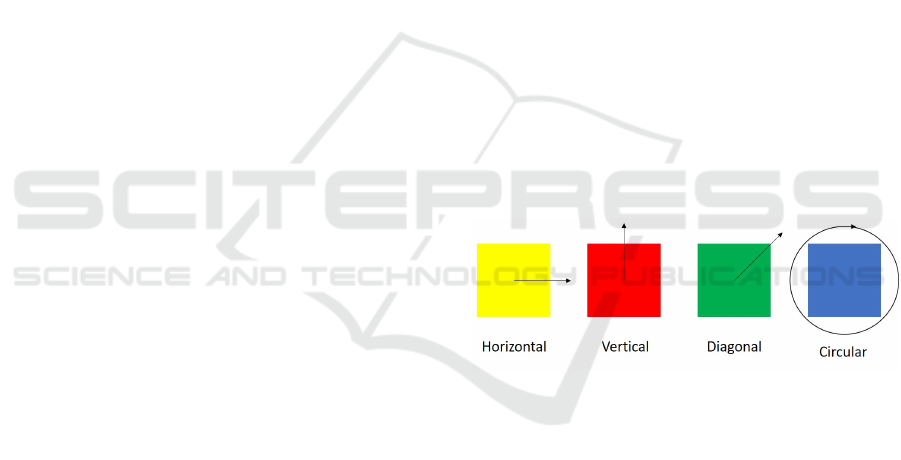
The type of movement of the stimulus can be di-
vided into four groups: horizontal, vertical, diago-
nal and circular, as shown in figure 1. Every type of
movement has the capability of being slow, moderate
and fast.
Figure 1: Types of movement - horizontal, vertical, diago-
nal and circular.
3 EYE TRACKER
An eye tracker was developed using the Matlab
R2017a software. Its main objective, as the name sug-
gests, is to keep track of the position of the eyes of the
subject under study, without any pre-calibration. The
target population for whom this software was devel-
oped were children with less than two years old (Jones
Petas Santos Dias, 2019).
The eye tracker was developed with the purpose of
being integrated in therapy sessions, while the chil-
dren are looking at the stimuli available on the Re-
habVisual platform. With this new tool, the thera-
pists would have a more objective way to understand
whether or not the child was following the stimuli.
BIODEVICES 2020 - 13th International Conference on Biomedical Electronics and Devices
236
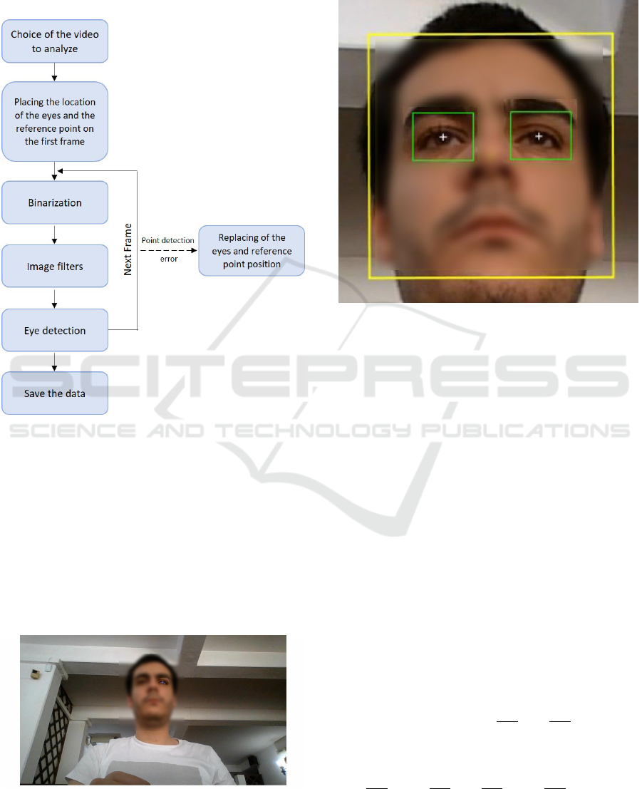
3.1 Implementation of the Eye Tracker
The software developed can be separated into the sec-
tions shown in figure 2.
Figure 2: Process summary.
The whole process, which occurs offline, begins
with the choice of the video, previously recorded, to
analyze. Immediately after choosing the video, the
first frame is shown to the user and he is asked to
click, using the cursor of the computer, on the eyes
and to choose a reference point. This section is made
using the getpts() function, which assigns coordinates
to the selected points. Usually, the reference point
chosen was the nose because it is equidistant to both
eyes and easy to track.
Figure 3: First frame with the left eye being selected.
After choosing the points, the analysis starts. Fig-
ure 4 represents a zoomed image of what is shown to
the user while the video is being analyzed.
Figure 4: Zoomed image of the video being analyzed.
The yellow box around the face represents the
face detector. This box is made by the function vi-
sion.CascadeObjectDetector(), available in the Com-
puter Vision Toolbox of Matlab.
The yellow point on the nose, represents the ref-
erence point. This point is tracked using the func-
tion vision.PointTracker(), which is also available in
the Computer Vision Toolbox. This function uses the
Kanade-Lucas-Tomasi algorithm to track a moving
point taking into account its features.
The white points represent the position of the cen-
ter of the eyes detected by the algorithm, which will
be discussed later.
The green boxes around the eyes, have fixed di-
mensions and are always centered on the position of
the eyes. Their color is green when the eye is be-
ing detected and red when it is not detected. The
boxes crop the image of the video using the im-
crop() function. The movement of these boxes is
explained in figure 5. The box is generated accord-
ing to its top left point. For example, if the eye has
the coordinates (x, y), the box will have as its top
left point coordinates (x −
dimx
2
, y −
dimy
2
), with dim
x and dim y being the fixed dimensions. If on the
next frame, the eye coordinates are (a, b), the new
coordinates of the top left corner of the box will be
(x −
dimx
2
+ a −
dimx
2
, y −
dimy
2
+ b −
dimy
2
). This way,
the eye will always be centered inside the box, making
it easier to detect it, even if the head slightly moves.
RehabVisual: Implementation of a Low Cost Eye Tracker without Pre-calibration
237
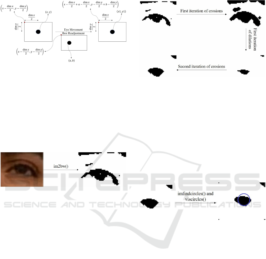
Figure 5: Scheme of the movement of the box.
The cropped image of the eye in the original video
is binarized by the function im2bw(). This function
has as input arguments, the image and the level of
luminance threshold. This threshold accepts values
between 0 and 1. The values of luminance under the
threshold are converted to black and the values above
are turned into white. The binarization is used be-
cause it makes it easier to detect the eye when com-
pared to the RGB image. The result of this function
is shown in figure 6.
Figure 6: Binarization of the image using the function
im2bw().
Three different types of image filters were used:
imerode(), imdilate() and medfilt2(). The first two are
used to erode and dilate, respectively, the binary im-
age, according to a structural element named strel.
The strel used in this algorithm was of the disk type
with a radius of 1. The erosion and dilation filtering
is made on the white part of the image, which means
that it will have the opposite effect on its dark part.
These filters are used with the objective of removing
the noise around the eyes, such as shadows and eye-
lids. The cycle used in this algorithm, consists of iter-
ations of erosions, followed by iterations of dilations,
finishing with another iteration of erosions, as shown
in figure 7.
The last one, the median filter, is used to remove
the ”salt and pepper noise”, that is, small dots that
have not been removed by the previous filters.
The eye detection is made by the function imfind-
circles(). This function is programmed to detect cir-
cles according to a radius range and sensitivity fac-
tor. Higher sensitivity level, means a higher num-
ber of circles detected, because it expands the search
to weak and partially obstructed circles. The radius
range used was between 6 and 12 and the sensitiv-
Figure 7: Scheme of the erosion and dilation filters.
ity level used was 0,90. An input argument of this
function called Object Polarity was also used with the
value dark, in order to detect black circles.
In order to guarantee that the circle detected in the
next frame is the eye, from all the circles detected in
the next frame, the circle chosen will be the one that
has the most similar coordinates to the one detected
previously.
To draw the circles, the function viscircles() was
used. It has as input arguments, the image and the
center and radius of the circle.
The detection of the eye is shown in figure 8.
Figure 8: Detection of the filtered image of the eye.
The data collected from each detected eye, each
box and the reference point is saved into matrices.
Each one has an horizontal position matrix and a ver-
tical position matrix. The final matrix for each posi-
tion is the sum of the matrix of the top left point of the
box with the correspondent eye and direction. Then,
this sum matrix is subtracted by the correspondent po-
sition matrix of the reference point.
In some situations, the analysis of the video stops
and the user has to manually click on the position of
the eyes and/or the reference point. This way, if the
eyes are not being detected, the user can manually in-
troduce the points. These situations are:
• Excessive rotation of the facial detector: When
a large rotation of the head occurs, one of the
eyes may not be detected. This way, the user can
skip between frames until the face is at a position
where both eyes can be detected.
• Program continues not running because the new
BIODEVICES 2020 - 13th International Conference on Biomedical Electronics and Devices
238

points have not been placed yet: When the pro-
gram stops because one of the conditions to stop it
is still activated, it only starts running again when
all the points are replaced. This way, the user can
skip between frames until reaching one that is in-
teresting to track.
• Change of size of the facial detector box: Since
this detector is used to correct some flaws regard-
ing the detection of the eyes, it is necessary that
its size does not change much. If the size exceeds
a certain limit, the user will replace the points and
a new facial detector is generated.
• Box of one of the eyes moves outside the facial
detector box: Another way to correct the non de-
tection of the eyes is to verify if the boxes created
around the eyes are inside the facial detector box.
If one of them goes out of the facial detector box,
the user reintroduces the points.
• Loss of validity of the reference point: Since the
video is recorded using the webcam of the laptop,
its quality is not always the best. Also, the lighting
conditions might not be the best as well. This way,
it might not always be possible for the tracker to
keep track of the reference point. If this condition
is true, the user has to reintroduce the reference
point again.
• Total loss of the facial detector: Related to the
problems described above, the facial detector
might have difficulty to trace every feature needed
to work properly. The detector stops working
when there are no longer enough feature points.
When this happens the user reintroduces the eyes’
position and reference point and a new face detec-
tor is created.
4 RESULTS
The results are displayed through graphics. The
graphics have represented on the x-axis the variable
count, which corresponds to the number of frames,
and on the y-axis the difference between the position
of the eye and the position of the reference point. The
reference point used was always the center of the nose
because it has the same distance between both eyes.
The videos recorded for this paper, were recorded
using the webcam of the laptop, which was located at
the bottom center of the screen. The videos had 30,03
frames per second and a quality of 720p. The distance
between the screen and the subject being recorded
was, approximately, 60 cm.
The eye tracker algorithm developed was tested on
healthy adults and healthy children under two years
old.
When the right eye is referred, this eye matches
the right eye of the individual. The same happens to
the left eye.
When a movement to the right is referred, this
movement means that the subject moved to their right
side.
• Horizontal Movement
– Left eye:
∗ Movement to the left: The left eye moves
away from the nose, so the difference will be
higher;
∗ Movement to the right: The left eye gets closer
to the nose, so the difference will be lower;
– Right eye:
∗ Movement to the left: The right eye gets closer
to the nose, so the difference will be lower;
∗ Movement to the right: The right eye moves
away from the nose, so the difference will be
higher;
• Vertical Movement
– Both eyes: Both eyes have the same kind of
response on the graphic when the individual
looks up or down.
∗ Looking up: When the subject looks up, the
center of the eye moves away from the ref-
erence point, so the difference between them
will be higher.
∗ Looking down: When the subject looks down,
the center of the eye gets closer to the ref-
erence point, so the difference between them
will be lower.
In this paper, an example of a healthy individual
is shown and its video acquisition was made under a
controlled environment and protocol.
In this example, the subject is a brown-eyed male,
without known evidences of visual impairment. The
distance between the laptop and the male is about 60
cm. The eye movements in the video were premed-
itated. The binarization threshold was 0,12 for both
eyes and two erosions were made followed by five di-
lations and, finally, three erosions.
The video has a duration of, approximately, 9,4
seconds and the head stands still until the 8,7 seconds
mark.
Figure 9 represents a frame taken from a video
where the subject is looking to the center. Figure
10 represents the variation of the horizontal position,
over time, of the subject’s left eye. The dot placed on
the graphic corresponds to the frame shown in figure
9.
RehabVisual: Implementation of a Low Cost Eye Tracker without Pre-calibration
239
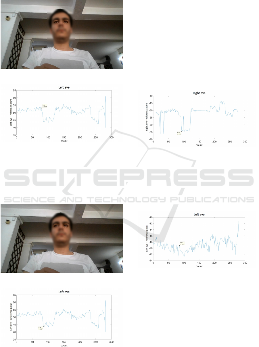
Figure 9: Picture of a subject looking at the center.
Figure 10: Graphic of the variation of the horizontal posi-
tion of the subject’s left eye.
Figure 11 represents a frame taken from a video
where the subject is looking to his right. Figure 12
shows the variation of the horizontal position, over
time, of the subject’s left eye. The dot placed on the
graphic corresponds to the frame shown in figure 11.
Figure 11: Picture of a subject looking to his right.
Figure 12: Graphic of the variation of the horizontal posi-
tion of the subject’s left eye.
Comparing the two graphics, it can be concluded
that an approximation of the left eye to the reference
point, leads to a decrease in their horizontal distance,
which translates in a decrease of the variable repre-
sented on the y axis of the graphic.
The graphic of the horizontal variation of the right
eye is shown in figure 13. The dot placed on the
graphic occurs during the same eye movement of fig-
ure 11, where the subject is looking to his right. Since
the right eye moves away from the reference point, the
difference of the horizontal position between them in-
creases. This translates into a decrease in the graphic,
as its y-axis is negative.
Figure 13: Graphic of the variation of the horizontal posi-
tion of the subject’s right eye.
Figure 11 also represents a frame taken from a
video where the subject is looking slightly up. Figure
14 represents the graphic of the variation of the verti-
cal position, over time, of the subject’s left eye. The
dot placed on the graphic corresponds to the frame
shown in figure 11.
Figure 14: Graphic of the variation of the vertical position
of the subject’s left eye.
Since the subject is looking up, the left eye moves
away, vertically, from the reference point. This means
that the two points are farther apart, which should re-
sult in a decrease in the graphic, as the y-axis is neg-
ative. However, the opposite occurs in this frame, as
the point shown is higher than the last one. This is
due to the fact that the human eye has an horizontal
elliptical shape, meaning that the range of movements
possible in the horizontal direction is higher than the
vertical direction. This means that the vertical posi-
tion will have larger margin for errors.
BIODEVICES 2020 - 13th International Conference on Biomedical Electronics and Devices
240
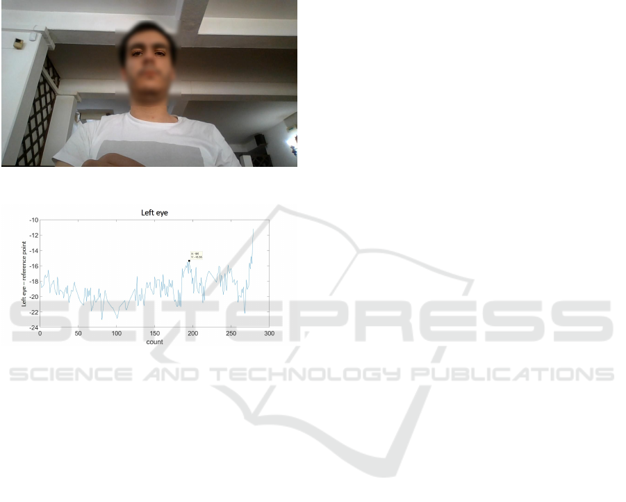
Figure 15 represents a frame taken from a video
where the subject is looking down. Figure 16 shows
the graphic of the variation of the vertical position,
over time, of the subject’s left eye. The dot placed on
the graphic corresponds to the frame shown in figure
15.
Figure 15: Picture of a subject looking down.
Figure 16: Graphic of the variation of the vertical position
of the subject’s left eye.
In this situation, the left eye gets closer to the ref-
erence point. This means that the vertical difference
between them decreases, which will correspond to a
rise in the graphic, because its y-axis is negative.
5 CONCLUSIONS AND FUTURE
WORK
The main purpose of this article was to develop an
eye tracker capable of showing the gaze direction of
children under two years old, that did not require pre-
calibration.
The results show that the eye tracker works in
detection of the variation of the horizontal position.
However, the variation of the vertical position is
harder to detect because of the horizontal elliptical
shape of the human eye.
As our eye tracker is still in its early stages, further
testing is needed to gather information to compare it
with other systems.
Regarding future work, an algorithm should be
developed in order to automatically choose the bi-
narization threshold and the number of iterations of
the erosion and dilation filters. Another algorithm
that should be developed is one that is able to auto-
matically detect the eye movements displayed in the
graphics.
ACKNOWLEDGEMENTS
The authors would like to thank all the healthcare pro-
fessionals of Hospital Dona Estef
ˆ
ania - Centro Hospi-
talar Lisboa Central.
REFERENCES
Agni, J., Cohen, J., Guthrie, J., Lucker, G., McElhearn, S.,
Mistrett, S., Morabito, V., Nickolai, L., Nozyce, M.,
Olitsky, S., Ricioppo, S., Rosen, I., Shanske, A., and
Gurland, J. (2007). Report of the Recommendations:
Vision Impairment. New York State Development of
Health, Clinical P(4970).
Bishop, V. E. (1998). Infants and Toddlers with Visual Im-
pairments. pages 1–26.
Jones Petas Santos Dias, P. H. (2019). Actualizac¸
˜
ao e
validac¸
˜
ao da plataforma RehabVisual: Ferramenta
para estimulac¸
˜
ao das compet
ˆ
encias visuomotoras.
Master’s thesis, Faculdade de Ci
ˆ
encias e Tecnologia
- Universidade Nova de Lisboa.
Machado, R., Ferreira, A., Quint
˜
ao, C., and Quaresma, C.
(2018). Rehabvisual: Development of an application
to stimulate visuomotor skills. BIODEVICES 2018
- 11th International Conference on Biomedical Elec-
tronics and Devices, Proceedings; Part of 11th Inter-
national Joint Conference on Biomedical Engineering
Systems and Technologies, BIOSTEC 2018, 1:173–
178.
Santos, C. (2018). Desenvolvimento e validac¸
˜
ao de uma
ferramenta para estimulac¸
˜
ao das compet
ˆ
encias visuo-
motoras em beb
´
es com alterac¸
˜
oes de desenvolvimento
decorrentes do nascimento. Master’s thesis, Facul-
dade de Ci
ˆ
encias e Tecnologia da Universidade Nova
de Lisboa.
World Health Organization (2019). Blindness and vision
impairment.
RehabVisual: Implementation of a Low Cost Eye Tracker without Pre-calibration
241
