
Refining Automation System Control with MDE
Pascal André
1
and Mohammed El Amin Tebib
2
1
LS2N, University of Nantes, CNRS UMR 6004, France
2
Davidson, Paris, France
Keywords:
Model Driven Engineering, Control Systems, Statecharts, Refinement, Model Transformation Process.
Abstract:
Software gets increasing matter in control systems such as cyber-physical systems and pervasive computing.
Beyond the reliability and performance requirements, the software must continuously evolve and adapt to new
needs and constraints from the physical world or technical support (reconfiguration and maintenance). Model
engineering aims to shorten the development cycle by focusing on abstractions and partially automating code
generation. In this article, we explore the assistance for stepwise transition from the models to the code
to reduce the application development time. The model covers structural, dynamic and functional aspects
of the control system. The target code is that of a system distributed over several devices. To conduct the
experiments, the models are written in UML (or SysML) and programs deployed on Android and Lego EV3.
We report the lessons learnt for future work.
1 INTRODUCTION
Software gets increasing matter in control systems
such as cyber-physical systems and pervasive com-
puting. Conversely the physical environment continu-
ously evolves and requires the software to be changed.
The development and maintenance lifecycle requires
means to assert the system functional and non func-
tional properties but also to (re)develop the applica-
tion code. Model Driven Engineering (MDE) (Bram-
billa et al., 2017) is an answer by focusing on abstrac-
tions and partially automating code generation. Rea-
soning to verify the system properties can happen at
the level of the models (there are methods and tools
for this) but more hardly at the code level, due to im-
plementation and distribution details. The code gen-
eration from high abstraction level models e.g. analy-
sis, still remains a costly software developer’s prerog-
ative. Automation becomes more cost-effective than
manual development when considering the evolution-
ary maintenance, including testing.
The transition from model to code remains a chal-
lenge from the point of view of automation (or as-
sistance) (Paige et al., 2016) especially for heteroge-
neous models of distributed (control) applications. By
heterogeneous we mean a model covers structural, dy-
namic and functional aspects. The code is the one of
a distributed application deployed over physical de-
vices. Despite a rich literature on the code genera-
tion from UML models (Ciccozzi et al., 2019; Ba-
jovs et al., 2013; Mukhtar and Galadanci, 2018), we
did not found a roadmap for practitioners. The ex-
isting approaches are often too specific or conversely
too general to apply in practice.
Our contribution is to highlight the problems by
comparing the approaches and to draw a vision and
guidelines for a generic MDE transformation process.
We rather focus on methodological issues than on
technical ones. We conduct empirical works with stu-
dents using trials and errors. We started from models
written with UML and we target programmable con-
trollers, Lego EV3 in this case, remotely controlled
by an android application. We compare three ways to
reach the source code: manual design, code genera-
tion and model transformation. The experiments il-
lustrate the complexity of the task. The lessons learnt
from these observations open tracks for future work.
The paper is structured as follows. Section 2 in-
troduces the context elements and then presents the
illustrating case study, a simple home automation (do-
motics) system. We overview three approaches to re-
fine models to code: fully manual in Section 3, fully
automatic in Section 4 and stepwise refinement in
Section 5. Ongoing experimentations are reported in
Section 6. The different approaches are illustrated on
the case study. Lessons learnt are discussed in Sec-
tion 7. Finally, Section 8 summarises the contribution
and draws the new vision perspectives.
André, P. and Tebib, M.
Refining Automation System Control with MDE.
DOI: 10.5220/0009147804250432
In Proceedings of the 8th International Conference on Model-Driven Engineering and Software Development (MODELSWARD 2020), pages 425-432
ISBN: 978-989-758-400-8; ISSN: 2184-4348
Copyright
c
2022 by SCITEPRESS – Science and Technology Publications, Lda. All rights reserved
425
2 CONTEXT
The goal is to set up a software production chain
based on models for distributed automation systems.
In particular, we target here programmable controllers
having a "real" execution environment that takes
into account operating, safety and performance con-
straints (Rierson, 2013). Some properties are gen-
eral (safety, liveness), others are related to the envi-
ronment or the system itself (energy, dangerousness,
quality of service...). From the software point of view
we consider at least two levels:
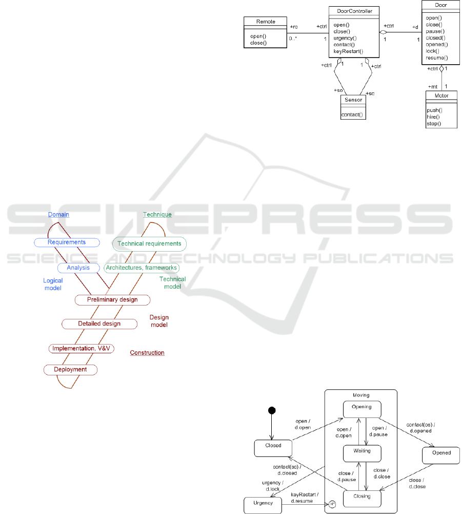
• the modelling and simulation level, where the in-
dividual and collective behaviours are described
and the constraints are analysed. The models at
this level will be called logical (or analysis) mod-
els in the sense that the technical details are not yet
given. The analysis model plunged into a techni-
cal environment will be called a design model, as
illustrated by the Y process of Figure 1.
• the operational level where the controllers of
the physical devices are implemented. This is
achieved using communication tools based on
programmable logic controllers (PLCs), robots,
sensors and actuators.
Figure 1: 2TUP Unified Process (Roques and Vallée, 2011).
In MDE, it is essential to ensure the model correct-
ness before starting the process of transformations
and code generation (André et al., 2017). This re-
duces the high cost of late detection of errors. What-
ever the modelling language is, the models are consid-
ered to be sufficiently detailed to be made executable.
In this work, the target technical platform includes
Java/Lejos for the control system and Java/Android
for the graphical human interface.
Case Study. We selected a simplified home au-
tomation equipment: a garage door including hard-
ware devices (remote control, door, PLC, sensor, ac-
tuators ...) and the software that drives these devices.
We assume the system behaviour to be simple enough
to be understood. We provide a logical model of the
case study in the UML notation e.g. the class diagram
of Figure 2.
Figure 2: Door garage class diagram.
The system operates as follows. Initially the door is
closed. The user starts opening the door by press-
ing the open button on his remote control. She can
stop the opening by pressing the open button again,
the motor stops. Otherwise, the door opens com-
pletely and triggers the open sensor so, the motor
stops. Pressing the close button will close the door
if it is (partially or completely) open. Closing can be
interrupted by pressing the close button again, the
motor stops. Otherwise, the door closes completely
and triggers a closed sensor sc, the motor stops. The
state diagram of Figure 3 describes the behaviour of
the door controller. The actions on the doors are prop-
agated to the engines by the door itself. At any time,
if someone triggers an emergency stop button located
on the wall, the door will lock. To resume we turn
a private key in a lock on the wall. The device state
machines are not given here. In the following, we as-
sume model properties to be verified some way.
Figure 3: Door controller State diagram.
MODELSWARD 2020 - 8th International Conference on Model-Driven Engineering and Software Development
426
3 FROM MODELS TO
IMPLEMENTATION
Software design is a key engineering activity that im-
plements a logical model inside a target technical plat-
form, taking decisions that affect the quality of the re-
sult. The result is a design model that covers comple-
mentary aspects such as persistence, concurrency, hu-
man interfaces, deployment in an architectural vision
that gradually reveals the details cf. Figure 1. Accord-
ing to the degree of automation, there are three main
alternatives to develop an application from a logical
model: (i) manual development, (ii) model transfor-
mation process, (iii) full automatic code generation.
In the remaining of this section, we report the manual
development. Section 4 overviews solutions for iii)
and Section 5 introduces a process for ii).
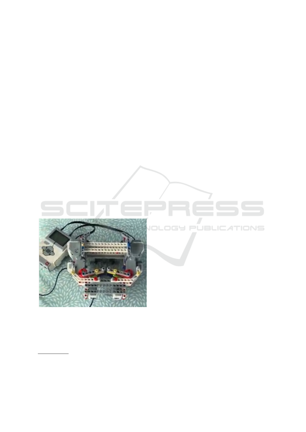
The case study was given to different groups of
students. The starting point was the logical model
figured in Section 2, documentation on EV3 Lejos, tu-
torial examples and also articles like (Hansen, 2011;
Niaz et al., 2004; Pilitowski and Dereziñska, 2007). A
first version
1
has been implemented with the physical
prototype of Figure 4 which has been extended later
with an android application to play the remote device
with bluetooth connection. Another group of students
implemented a different version
2
.
Figure 4: Lego prototype of the door system.
The code they produced does not fully conform to
the logical models which were perceived as a doc-
umentation reference rather than an abstract model.
The detailed design decisions are different. In ver-
sion v1 the students used enum types to implement
1
https://github.com/demeph/TER-2017-2018
2
https://github.com/FrapperColin/2017-2018/tree/
master/IngenierieLogicielleDomoDoor
state machines while a state pattern has been cho-
sen in version v2. The remote device was also im-
plemented in different ways according to the student
experience and motivation: from java swing GUI with
wired TCP-IP communication with EV3 or Android
app with bluetooth or wifi connection. Finally, the
prototype of Figure 4 uses two motors for two door
swings while a single door and motor were speci-
fied in the logical model. Isolating the various design
choices is a main stage to rationalize development in
a refinement process (see Section 5).
4 CODE GENERATION,
EXECUTION
UML Tool Code Generation. We compared code
generation facilities of UML (visual) tools according
to selected features. Our panorama is definitely not
an exhaustive study but show tendencies in some big
categories prototypes (free, eclipse modelling, case
tools...). The model interoperability is ensured by
the XMI standards. Unfortunately, the diagram in-
terchange standard is less interoperable. The tools
enable to edit class diagrams (CD) and State transi-
tion diagrams (STD) and (re)generate source code.
Despite a link exists between method body and ac-
tivity diagrams we did not seen concretely it in the
tools. Usually they provide the operation signature
but rarely more except when a round trip engineering
is allowed that enables to attach target code fragments
to model operations in order to keep them when re-
generating the code after model evolution.
• StarUML is a free UML editors. It generates the
structural and type declarations of the class dia-
grams but not the operations body or STDs.
• Papyrus and Modelio represent the Eclipse Mod-
eling open source ecosystem with an active com-
munity. The code generator (native C++ and Java)
includes operation behaviours with round trip. We
did not found an adequate plugin for STDs and
the associations were not generated in the Java
code. Modelio includes round trip but unlike Vi-
sual Paradigm, it makes the difference between
the methods managed by Modelio and the others.
A managed method is automatically generated for
each release. A simple (not managed) method
is under the responsibility of the developer. In
this category, also mention UML Designer Obeo
tools, and Acceleo, or the Polarys project.
• Yakindu by Itemis is a tool for STDs. Its code
generator provides a detailed code for one STD
only which does not match with classes and object
communication. A Java generation from UML
Refining Automation System Control with MDE
427

Table 1: Comparison of some tools with code generators.
Star UML Papyrus Yakindu Modelio VisualParadim IBM rational rhapsody
UML - XMI 2.0 2.5 - 2.4.1 2.0 2.4.1
CD
√ √
-
√ √ √
STD - - one only
√
1
√ √
Operations - incremental - RoundTrip RoundTrip
√
Round-trip - override -
√ √ √
MOM - - - - - -
API Mapping - - - - - -
Licence
d
F, C O F, C O C C
1
Extension in http://www.sinelabore.com/doku.php?id=wiki:landing_pages:modelio
state machines is detailed in (Hansen, 2011).
• Visual Paradigm is very rich in standards and fea-
tures. It supports the generation of class diagrams
and STDs in Java, C++ or VB.net. Its round-trip
engineering feature synchronizes the code and the
model. We did not have access to the generated
code to estimate the programming effort to add
communication between STDs.
• IBM Rational Rhapsody appears to be the refer-
ence tool. The code is updated automatically in
a parallel with the model. One can edit the code
directly, the diagrams will stay in synchronised.
Again we did not have access to the generated
code to estimate the manual contribution.
Most of the tools are not bound to one language only,
for example Modelio, Papyrys or Visual Paradigm
integrate different OMG standards such as SysML,
BPMN... Consequently some of the tools can have
esoteric notations for some model elements. Also sev-
eral tools cover a larger perimeter than system mod-
elling, covering parts of enterprise architecture.
Table 1 summarizes some selected features.
MOM (Message Oriented Middleware) stands for
concrete implementations of the UML message send
or signal raising. We call API Mapping a facility to
map model elements to predefined libraries elements.
The license may be OpenSource, Free, Commercial.
Table 1 illustrates the fact that, to our knowledge, no
tool deals clearly yet with the problem of (hetero-
geneous) communication middleware or to mapping
with technical features (high level for architectures,
low level for framework libraries) except embedding
in a given context like Java, .NET, REST... However,
we noted that Visual Paradigm can integrate deploy-
ment models in the cloud. IBM Engineering Systems
Design Rhapsody is rather dedicated to detailed de-
sign. Some tools also offer persistence features (e.g.
mapping object relations or SQL) that we have not
be retained here since we focus on automation. Note
also that during our experiments, we used Papyrus to
generate class diagrams in Java.
Executable UML. The ultimate code generation is
to execute UML models. Several attempts exist since
2000’s. There were specific to a given technical ar-
chitecture or even a given framework and often lim-
ited to simple cases like the CRUD (Create, Read,
Update, Delete) application generation on simple re-
lational databases. The technical framework must be
generic and complete, but also the models must be
simple. We can also generate plain source code to an-
imate (operational) specifications.
The prerequisites are a complete language and
a formal semantics. Diagrams are usually not suf-
ficient to describe a operational system. One can
add constraints written in OCL (for invariant and
pre/post-condition assertions) or pseudo-code writ-
ten in a language conforming to the Action Seman-
tics (AS). Compare to source code annotations, OCL
or AS expressions remain abstract vs the target plat-
form. The concept of action is present in activity
and state transitions diagrams. Action Semantics has
been defined by a meta-language since UML 1.4 but
no standard concrete syntax was proposed. Early
concrete syntaxes were associated to XUML tools,
especially for real-time systems: (i) Action Spec-
ification Language (ASL) was defined for iUML-
Lite of Kennedy-Carter (Abstract Solutions) support-
ing xUML (Raistrick et al., 2004). (ii) BridgePoint
Action Language (AL) (and the derived SMALL,
OAL, TALL) proposed by Balcer & Mellor was
implemented in xtUML of Mentor Graphics (Mel-
lor and Balcer, 2002). (iii) Kabira Action Seman-
tics (Kabira AS) proposed by Kabira Technologies
(and later TIBCO Business Studio). Other proposals
are Platform Independent Action Language (PAL) of
Pathfinder Solutions, or SCRALL which had a visual
representation.
All these efforts led to a semantics for a subset of ex-
ecutable UMLs, called fUML (OMG, 2018), with now
a normalized concrete syntax Alf. A reference im-
plementation exists
3
that we plan to integrate later in
3
http://modeldriven.github.io/fUML-Reference
-Implementation/
MODELSWARD 2020 - 8th International Conference on Model-Driven Engineering and Software Development
428

the project. We did not experimented the "executable"
approach yet since out goal was not to execute or to
animate UML models but to design applications.
5 DESIGN TRANSFORMATION
PROCESS
In MDE a transformation process implements refine-
ments from Platform Independent Model (PIM) to
(more) concrete Platform Specific Model (PSM). As
exhibited by Figure 1, the software design consists in
"weaving" the logic model to the technical infrastruc-
ture (platform) to obtain in fine an executable model.
We draw the reader’s attention to the following ob-
servations : (i) Only a complete (and consistent)
logical model enables to reach an executable source
code. Model transformation can infer but not invent.
(ii) The generation of code itself is not conceivable
as a single transformation step, because of the seman-
tic distance between the logical model and the tech-
nical target, especially if it is composed of orthogo-
nal but related aspects, called domains (e.g. persis-
tence, GUI, control, communications, inputs/outputs)
on which the logical model must be "woven". (iii) De-
sign is by nature an engineering activity, linked to
the designers’ experience. A process can be auto-
mated only if all the activities are known precisely.
(iv) MDE practice shows that transformations are ef-
fective when the source and target models are seman-
tically close e.g. class diagram and relational model
for persistence. (v) The transformations comply an al-
gorithmic style (e.g. Kermeta
4
) or a rule-based style
(e.g. ATL
5
). Working with small transformations en-
ables to make them more verifiable and reusable.
On the basis of these considerations we adopt a
principle of small step transformations. The com-
plexity (or intelligence) should not be in the atomic
transformations but in the transformation processes it-
self. A complex transformation is hierarchically com-
posed of other transformations, until atomic trans-
formations. Figure 5 sketch the aspects to con-
sider to refine towards implementation. These macro-
transformations use configuration information.
• T1 starts by structuring subsystem applications
with a mapping on the application architecture by
describing the APIs and the communication pro-
tocols. Of course, if the logical model includes
component and deployment diagrams for a pre-
liminary design in figure 1, T1 will be simplified.
• In T2, for each kind of communication, the UML
4
http://diverse-project.github.io/k3/
5
https://www.eclipse.org/atl/
message send are refined according to the protocol
under consideration (called MOM in Table 1). At
least, in a sequential implementation, we simply
send messages in the target OOP language (Java,
C++ or C#).
• T3 transforms state machines into a OOP model
which in general does not natively include this
concept. We can use enum types or State pattern
depending on the situation. This thorny problem
is overviewed in Section 6.
• T4 aims to match model elements to predefined
libraries of the technical frameworks. For ex-
ample, the class Motor is implemented by the
class lejos.robotics.RegulatedMotor. This API
mapping requires adaptors for message send or
method call according two ways: (i) encapsulate
the predefined class in the model class and use
it by delegation, the advantage is to preserve the
model API. (ii) substitute the class of the model
by the predefined class and rename the calls to the
API of the model (we lose traceability).
Note that the transformation parameters and decisions
must be stored to replay the transformation process in
case of evolution of the initial model. The process of
Figure 5 is abstract and generic. Optimizations are
possible considering round trip or model animation.
6 EXPERIMENTATIONS
In this section, we report elements of students’ inves-
tigations for the STDs to Java transformation, a subset
of the T3 (macro-)transformation of Figure 5. Trans-
formation T1 and T2 were implemented manually.
Due to its expressivity and abstraction, we chosed
ATL
6
to conduct these experiments. ATL is a model
transformation language based on non-deterministic
transformation rules. In a model to model (M2M)
ATL reads a source model conforming to the source
meta-model and produces a target model conforming
to the target meta-model. In the last transformation
we used model to text (M2T) transformation to gen-
erate java source code. The refine mode of ATL en-
ables to handle partial homomorphic transformations.
In this mode, the source and target models share the
same meta-model. We thereby limit the number of
metamodels or profiles by keeping standard UML as
far as we can. A rule can modify, create, or delete
properties or attributes in a model.
The input model is a Papyrus model (XMI format
for UML 2.5). We assumed simple automata only:
no composite states, no real time, no history. Also
6
https://www.eclipse.org/atl/
Refining Automation System Control with MDE
429
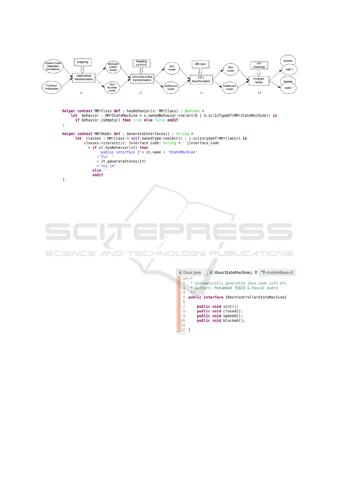
Figure 5: General transformation process.
Figure 6: ATL transformation rule for state diagrams.
a main restriction is that state machine inheritance
through class inheritance is not allowed because the
UML rules for it are fuzzy. Code style conventions
have been determined (for example, the elements Re-
gion and StateMachine have the name of their class)
that make it easier to write the transformation rules.
In a first trial, the students proposed a 4-step
transformation to implement each (sequential) STD
by a small machinery: (i) T3-1: The states names
are the values of an Enumeration type. (ii) T3-2:
A currentState variable is defined to store the
current state, it is initialised with the initial state
value. (iii) T3-3: For each operation correspond-
ing to an event, a case clause is introduced as a
<before><after> aspect to check if the operation is
callable in the currentState. If no action descrip-
tion exist, the non-trivial operation behaviour is left
to programmers by a method call <op>_beh with the
same parameters (in a round trip style). (iv) T3-4:
The STDs are removed from the model. The transfor-
mations used visitor patterns to extract informations
from the source model.
In a second trial, we defined two ATL transforma-
tions to parse the model and generate the code.
1. The rules of the first transformation generate the
static structure based on parsing class diagrams.
Four ATL helpers (methods) are defined to parse
the XMI model, each helper generates a piece of
code that conforms to the Java grammar (syntax).
For example the ATL helper GenerateClasses()
generates the Java class’ code structure, this
helper calls other ones (GenerateAttibutes(),
GenerateMethods()) to obtain the complete code.
2. The second transformation goal is to provide a
complete generation engine from statecharts. An
example of ATL rules is described Figure 6. Fol-
lowing a State pattern, we use helpers to generate
the states machine related to each object, this ob-
ject should implements the interface that declares
the fundamental methods to initialize, enter, and
exit a state machine. Figure 7 is a screenshot of
the interface of the door states.
Figure 7: ATL transformation rule for state interface.
These experiments highlight the complexity of the
problem and some basic aspects to deal with. The
results are still quite far from the final objectives.
7 DISCUSSIONS
We discuss here some lessons learnt from the above
studies.
MODELSWARD 2020 - 8th International Conference on Model-Driven Engineering and Software Development
430
The manual design of the application from a log-
ical model was not difficult to the students, except
learning the target technical environment. However,
their code did not fully conforms the initial model.
Of course there are technical constraints but also free
interpretation. For example the Lego model uses two
motors (one per door panel) and not a single engine
as in the model. The manual design shows various or-
thogonal aspects that were are not a priori prioritized
by the students. Dependencies remain implicit for
them, even if they realize that choices for one aspect
will influence other aspects. The wireless communi-
cation between the remote control and the controller
remains abstract in the form of sending messages in
the model. Some implementation issues imply a feed-
back on the initial models which, although detailed,
did not guarantee the consistency or completeness of
the system specification.
The automatic generation of code provides an in-
complete model, which often does not even exploit
the information of the model (OCL constraints, oper-
ation details). Although many studies have been con-
ducted, the systematic study (Ciccozzi et al., 2019)
shows that the execution of UML models remains a
difficult problem and answers to animation needs not
to software development. The new standards fUML
and Alf contribute to palliate a lack in action mod-
elling. They have been implemented in the verifica-
tion of models (Planas et al., 2016), execution via
C++ (Ciccozzi, 2018) or MoKa/Papyrus (Guermazi
et al., 2015).
In the design transformation process, we ordered
the transformations according to their impact level:
architectural choices (deployment, communications),
general design choices (programming language), de-
tailed design choices (patterns, library mapping).
This workflow remains abstract because the macro-
transformation and the parameters to provide remain
substantial. It must be customised to each context.
For example, coding state machines is subject to
interpretation and strongly related to the execution
model (Pilitowski and Dereziñska, 2007). The im-
plement strategy (enumerations, State pattern, execu-
tion engine) may vary according to the STD nature
or the programming language features. For example,
we advise (i) boolean types for two state automata,
(ii) enumerations types for small automata, (iii) State
pattern if the associated operations have different be-
haviour from one state to another, (iv) full STD in-
strumentation (framework API) for STDs beyond 10
states. These strategies should be parametrisable in
the transformation process. We also believe that sev-
eral transformation tools should be used because the
rule-based approach is unsuitable in some operational
transformations like the one mentioned in (Pilitowski
and Dereziñska, 2007). The anchoring to the tech-
nical platform can be given by a mapping to types,
classes and operations. The human intervention in
transformations remains predominant when there are
alternative choices, such as state machines or message
send detailed design. The process has to be more ra-
tionalised to be assisted by the means of interactive
design decisions. This point remains premature in the
state of our experiments.
SysML (Weilkiens, 2008) is recommended for the
design of control systems. We found an example
of transmission control for Lego NXT
7
. Its SysML
model is very detailed and can then be simulated by
the Cameo tool. Modelling with SysML is suitable
but it does not fundamentally change the problem. We
used UML because it belongs to the student program.
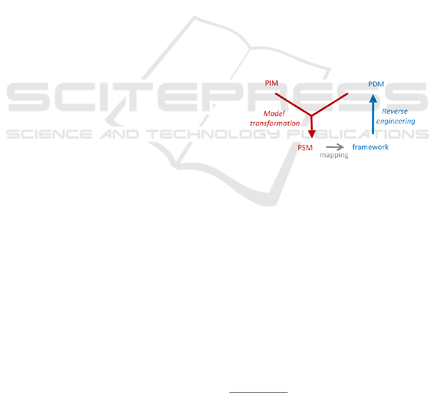
The experimentations changed our vision. De-
sign is more than refinement, which assumes that the
concrete models add details to abstract models. We
perceive design as a set of parallel mapping transfor-
mations from a PIM to PDM (Platform Description
Model) leading to a PSM, as illustrated in the pattern
of Figure 8.
Figure 8: Mapping transformation pattern.
• The input PIM must be checked (model verifica-
tion and testing but also conformity to modelling
rules and annotations coming from the transfor-
mation process experience.
• Everything is model until the last level which is
code generation.
• There are at least four frameworks to be compliant
with the design process of Figure 5.
• The more you advance in the transformation pro-
cess the more you can process transformations in
parallel: one for T1, then one by deployment node
in T2, then one by middleware in T3, etc.
• Transformations should be hierarchically com-
posable in transformation processes (composite)
and parametrisable.
• Accordingly, the verification and the test of mod-
els can be inserted at any time in the process (An-
dré et al., 2017).
7
https://tinyurl.com/wkja25u
Refining Automation System Control with MDE
431

• The missing link is usually a PDM, a model of the
target framework. A PDM is now mandatory. It
can be obtained by model driven reverse engineer-
ing (André, 2019).
8 CONCLUSION
The maintenance of control systems software high-
lights the need for industrialisation tools that go be-
yond integrated development. The manual develop-
ment enables to carry the main design decisions but
takes time and is subject to the developers experience
and availability especially during maintenance. The
code generators of many case tools typically produce
skeletons where the bulk of the development remains
to be done. Integrated MDA solutions exist but for
a limited range of application. We propose a generic
model transformation workflow where the complexity
should rely to the process not the atomic transforma-
tions. To reduce a technical debt, we must abstract
the infrastructure and reason at the model level while
helping to refine these models. Enriching models, for-
malizing development processes, making composable
customized transformations are tracks we follow.
Much work remains to be done, that are challeng-
ing. From a theoretical point of view, the transforma-
tion processes remain little explored. One perspective
is to design an algebra of transformations to combine
them by assertion conditions. From a practical point
of view, we still need to rationalise the software en-
gineering process as a combination of decisions and
experiment with a typology of transformations. From
a tooling point of view, it is necessary to be able to
reverse engineering the design frameworks as PDM
and to combine transformations written in different
languages and that are interactive so that the designer
influences the design choices.
REFERENCES
André, P., Attiogbé, C., and Mottu, J.-M. (2017). Combin-
ing techniques to verify service-based components. In
Proceedings of AMARETTO@MODELSWARD 2017,
Porto, Portugal.
André, P. (2019). Case studies in model-driven reverse en-
gineering. In Proceedings of MODELSWARD 2019,
Prague, Czech Republic, February 20-22, 2019, pages
256–263.
Bajovs, A., Nikiforova, O., and Sejans, J. (2013). Code gen-
eration from uml model: State of the art and practical
implications. Applied Computer Systems, 14(1):8–18.
Brambilla, M., Cabot, J., and Wimmer, M. (2017). Model-
Driven Software Engineering in Practice: Second
Edition. Morgan & Claypool Publishers, 2nd edition.
Ciccozzi, F. (2018). On the automated translational execu-
tion of the action language for foundational uml. Soft-
ware & Systems Modeling, 17(4):1311–1337.
Ciccozzi, F., Malavolta, I., and Selic, B. (2019). Execution
of uml models: a systematic review of research and
practice. Software & Systems Modeling, 18(3):2313–
2360.
Guermazi, S., Tatibouet, J., Cuccuru, A., Seidewitz, E.,
Dhouib, S., and Gérard, S. (2015). Executable model-
ing with fuml and alf in papyrus: Tooling and experi-
ments. In Proc. of the 1st International Workshop on
Executable Modeling in (MODELS 2015)., pages 3–8,
Ottawa, Canada.
Hansen, M. O. (2011). Exploration of UML State Machine
implementations in Java. Master’s thesis, University
of Oslo, Norway.
Mellor, S. J. and Balcer, M. J. (2002). Executable UML:
A Foundation for Model-Driven Architecture. Object
Technology Series. Addison-Wesley, 1 edition. ISBN
0-201-74804-5.
Mukhtar, M. I. and Galadanci, B. S. (2018). Automatic
code generation from uml diagrams: the state-of-the-
art. Science World Journal, 14(4):47–60.
Niaz, I. A., Tanaka, J., and Words, K. (2004). Mapping uml
statecharts to java code. In in Proc. IASTED Interna-
tional Conf. on Software Engineering (SE 2004, pages
111–116.
OMG (2018). Semantics of a Foundational Subset for Exe-
cutable UML Models (fUML), version 1.4. Technical
report, Object Management Group, https://www.omg.
org/spec/FUML/1.4/.
Paige, R. F., Matragkas, N., and Rose, L. M. (2016). Evolv-
ing models in model-driven engineering: State-of-the-
art and future challenges. Journal of Systems and Soft-
ware.
Pilitowski, R. and Dereziñska, A. (2007). Code generation
and execution framework for uml 2.0 classes and state
machines. In Innovations and Advanced Techniques in
Computer and Information Sciences, pages 421–427.
Springer.
Planas, E., Cabot, J., and Gómez, C. (2016). Lightweight
and static verification of uml executable models. Com-
put. Lang. Syst. Struct., 46(C):66–90.
Raistrick, C., Francis, P., Wilkie, I., Wright, J., and Carter,
C. B. (2004). Model Driven Architecture with Exe-
cutable UML. Cambridge University Press. ISBN 0-
521-53771-1.
Rierson, L. (2013). Developing Safety-Critical Software: A
Practical Guide for Aviation Software and DO-178C
Compliance. Taylor & Francis.
Roques, P. and Vallée, F. (2011). UML 2 en action: De
l’analyse des besoins à la conception. Architecte logi-
ciel. Eyrolles. (in french).
Weilkiens, T. (2008). Systems Engineering with SysM-
L/UML: Modeling, Analysis, Design. The MK/OMG
Press. Elsevier Science.
MODELSWARD 2020 - 8th International Conference on Model-Driven Engineering and Software Development
432
