
Image-based Material Editing for Making Reflective Objects Fluorescent
Daichi Hidaka and Takahiro Okabe
Department of Artificial Intelligence, Kyushu Institute of Technology, Japan
Keywords:
Image-based Material Editing, Photometric Consistency, Fluorescence, Reflection, Spectral Irradiance.
Abstract:
Fluorescent materials give us a unique sense of quality such as self-luminous ones, because they absorb light
with certain wavelengths and then emit light with longer wavelengths. The existing methods for image-based
material editing make objects in an image specular, translucent, and transparent, but they do not address
fluorescent materials. In this paper, we propose a method for making reflective objects in a single input image
fluorescent by adding photorealistic fluorescent components to the objects of interest. Specifically, we show
that photometrically consistent fluorescent components can approximately be represented by using the 3-band
(RGB) spectral irradiance on the surface of a reflective object, and then compute the fluorescent components
on the basis of intrinsic image decomposition without explicitly estimating the object’s shape and the light
sources illuminating it from the input image. We conducted a number of experiments using both synthetic and
real images, and confirmed that our proposed method is effective for making reflective objects fluorescent.
1 INTRODUCTION
Fluorescence is a very common phenomenon ob-
served both in natural objects such as minerals and
plants and in man-made objects such as papers and
clothes (Barnard, 1999). Fluorescent materials ab-
sorb light with certain wavelengths and then emit light
with longer wavelengths, in contrast to reflective ma-
terials which reflect light with the same wavelengths
as those of the incident light. Therefore, they give us
a unique sense of quality such as self-luminous mate-
rials.
Image-based material editing is a technique for
automatically and photo-realistically replacing one
material in an image with another. Khan et al. (Khan
et al., 2006) propose a method for making an object in
a single input image specular, translucent, and trans-
parent. Since the appearance of an object depends on
the shape of the object and the light sources illumi-
nating it, their proposed method roughly estimates the
depth map of the object and the illumination distribu-
tion of a scene from the input image on the basis of
heuristics. Liu et al. (Liu et al., 2017) propose an end-
to-end network architecture that predicts the shape,
illumination, and material from a single image, and
make use of the predicted results for material editing
of diffuse and specular objects.
On the other hand, fluorescent materials are not
addressed in the context of image-based material edit-
ing. They are addressed mainly in the context of re-
flection separation, i.e. separating reflective and flu-
orescent components under narrow-band camera as-
sumption (Zhang and Sato, 2013), under narrow-band
illumination assumption (Koyamatsu et al., 2019),
and by using high-frequency illumination in the spec-
tral domain (Fu et al., 2016b), and in the context of
image-based modeling, i.e. recovering the spectral
properties of reflection and fluorescence (Fu et al.,
2016a).
In this paper, we propose a method for making re-
flective objects in a single input image fluorescent by
adding photorealistic fluorescent components to the
objects of interest. Specifically, we show that pho-
tometrically consistent fluorescent components can
approximately be represented by using the 3-band
(RGB) spectral irradiance on the surface of a reflec-
tive object. Therefore, our proposed method com-
putes the fluorescent components on the basis of in-
trinsic image decomposition (Tappen et al., 2005)
without explicitly estimating the object’s shape and
the light sources illuminating it from the input image.
We conducted a number of experiments using both
synthetic and real images, and confirmed that the ap-
proximation represented by using the 3-band spectral
irradiance works well and that our proposed method
is effective for making reflective objects fluorescent.
The application scenarios of our method include the
appearance simulation of fluorescent materials for
traffic signs, commercial posters, manufactured prod-
ucts, and so on.
Hidaka, D. and Okabe, T.
Image-based Material Editing for Making Reflective Objects Fluorescent.
DOI: 10.5220/0009146103550360
In Proceedings of the 15th International Joint Conference on Computer Vision, Imaging and Computer Graphics Theory and Applications (VISIGRAPP 2020) - Volume 1: GRAPP, pages
355-360
ISBN: 978-989-758-402-2; ISSN: 2184-4321
Copyright
c
2022 by SCITEPRESS – Science and Technology Publications, Lda. All rights reserved
355

The main contributions of this study are twofold.
First, based on the fluorescent model, we show that
photometrically consistent fluorescent components
can approximately be represented by using the 3-band
spectral irradiance on the surface of a reflective ob-
ject. It enables us to compute the fluorescent com-
ponents on the basis of intrinsic image decomposi-
tion without explicitly estimating the object’s shape
and the light sources illuminating it from an input im-
age. Second, we experimentally confirmed that our
proposed method is effective for making reflective
objects in a single input image fluorescent. Specif-
ically, we confirmed that the approximation repre-
sented by using the 3-band spectral irradiance works
well through qualitative and quantitative evaluation
using synthetic images, and that our method provides
visual enrichment of photographs with virtual fluores-
cence.
2 PROPOSED METHOD
2.1 Overview
For fluorescent materials, the pixel value i
b
(x
x
x) at a
point x
x
x on an object surface consists of a reflective
component r
b
(x
x
x) and a fluorescent component f
b
(x
x
x)
as
i
b
(x
x
x) = r
b
(x
x
x) + f
b
(x
x
x), (1)
where b (b = 1, 2, 3) stands for the band (RGB) of a
color camera. Our proposed method assumes that an
object of interest has only the first term, i.e. the re-
flective component, and then adds the second term,
i.e. the fluorescent component to the object surface.
In this section, we explain the fluorescence model
and the diffuse reflection model, and then explain our
method for computing photometrically consistent flu-
orescent components.
2.2 Fluorescence Model
In general, a pure fluorescent material absorbs light
with a certain wavelength λ
0
, and then emits light
with a longer wavelength λ
00
. Those properties are
described by the absorption spectrum a(λ
0
) and the
emission spectrum e(λ
00
) (Zhang and Sato, 2013).
When a fluorescent material is illuminated by dis-
tant light sources from various directions with various
wavelengths, the fluorescent component is given by
f
b
(x
x
x) =
Z
a(λ
0
)
Z
l(ω
ω
ω, λ
0
)ω
ω
ω
>
n
n
n(x
x
x)dω
ω
ω
dλ
0
×
Z
c
b
(λ
00
)e(λ
00
)dλ
00
. (2)
Here, l(ω
ω
ω, λ
0
) describes the energy of the light rays
from the direction ω
ω
ω and with the wavelength λ
0
, i.e.
the spectral illumination distribution of a scene. n
n
n(x
x
x)
and c
b
(λ
00
) are the surface normal at the point x
x
x and
the b-th band’s spectral sensitivity of a camera respec-
tively. It is reported that the brightness of a fluorescent
component approximately obeys the Lambert model,
i.e. is represented by the inner product between the
surface normal and the light source direction (Sato
et al., 2012; Treibitz et al., 2012).
We assume that the spectral sensitivity of a camera
is narrow-band as is often assumed in color constancy
algorithms. Namely, the spectral sensitivity is approx-
imately represented by using the Dirac delta function;
c
b
(λ
00
) ' δ(λ
00
− λ
b
). Then, the integral with respect
to λ
00
in eq.(2) is represented as
Z
c
b
(λ
00
)e(λ
00
)dλ
00
' e(λ
b
), (3)
where we assume the peak value of the spectral sen-
sitivity is 1 for the sake of simplicity.
The integral with respect to ω
ω
ω in eq.(2) is the spec-
tral irradiance s(x
x
x, λ
0
) due to incident light rays from
various directions to the point x
x
x with the wavelength
λ
0
, and is defined by
s(x
x
x, λ
0
) ≡
Z
l(ω
ω
ω, λ
0
)ω
ω
ω
>
n
n
n(x
x
x)dω
ω
ω. (4)
We substitute eq.(4) into the integral with respect to λ
0
in eq.(2), and then approximately represent the inte-
gral by the summation with respect to the wavelengths
of the 3 bands as
Z
a(λ
0
)s(x
x
x, λ
0
)dλ
0
'
∑
b
a(λ
b
)s(x
x
x, λ
b
). (5)
Substituting eq.(3) and eq.(5) into eq.(2), we obtain
f
b
(x
x
x) ' e(λ
b
)
∑
b
0
a(λ
b
0
)s(x
x
x, λ
b
0
). (6)
Therefore, the brightness of the fluorescent compo-
nent is computed by the sum of the products between
the 3-band absorption spectrum a(λ
b
0
) and the 3-band
spectral irradiance s(x
x
x, λ
b
0
). The color of the fluores-
cent component is determined by the 3-band emission
spectrum e(λ
b
).
2.3 Diffuse Reflection Model
According to the Lambert model, the diffuse reflec-
tion component is described as
r
b
(x
x
x) =
Z
c
b
(λ
0
)ρ(x
x
x, λ
0
)
Z
l(ω
ω
ω, λ
0
)ω
ω
ω
>
n
n
n(x
x
x)dω
ω
ω
dλ
0
=
Z
c
b
(λ
0
)ρ(x
x
x, λ
0
)s(x
x
x, λ
0
)dλ
0
(7)
GRAPP 2020 - 15th International Conference on Computer Graphics Theory and Applications
356
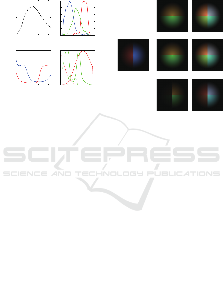
(a) (b)
(c) (d)
400 500 600 700
0
0.2
0.4
0.6
0.8
1
400 500 600 700
0
0.2
0.4
0.6
0.8
1
400 500 600 700
0
0.2
0.4
0.6
0.8
1
400 500 600 700
Figure 1: The spectral data for synthetic images. (a) the
spectral intensity of a light source, (b) the spectral sensitiv-
ity of a camera, (c) the spectral reflectances of a reflective
object (red: left, blue: right), and (d) the absorption and
emission spectra of fluorescent materials (red: upper, green:
lower).
Here, ρ(x
x
x, λ
0
) is the spectral reflectance at the point x
x
x,
and we use the definition of the spectral irradiance in
eq.(4).
Assuming a narrow-band camera in a similar man-
ner to the previous subsection, the diffuse reflection
component is given by
r
b
(x
x
x) ' ρ(x
x
x, λ
b
)s(x
x
x, λ
b
). (8)
Therefore, the diffuse reflection component is com-
puted by the products between the 3-band spectral re-
flectance ρ(x
x
x, λ
b
) and the 3-band spectral irradiance
s(x
x
x, λ
b
).
2.4 Adding Fluorescence
Our proposed method adds fluorescent components,
whose absorption spectrum a(λ
0
) and emission spec-
trum e(λ
00
) are specified by a user
1
, to an object sur-
face of interest in a single input image. Since both
the 3-band absorption spectrum a(λ
b
) and the 3-band
emission spectrum e(λ
0
b
) in eq.(6) are given, the prob-
lem of computing photorealistic fluorescent compo-
nents results in the estimation of the 3-band spectral
irradiance s(x
x
x, λ
0
b
).
On the other hand, the diffuse reflection compo-
nents also depend on the 3-band spectral irradiance as
shown in eq.(8), and therefore we can estimate the 3-
band spectral irradiance from them. Specifically, we
1
The absorption and emission spectra can be selected
from the McNamara dataset (McNamara et al., 2006).
(a)
(b) (c)
(d) (e)
(f) (g)
Figure 2: The experimental results using synthetic images.
(a) the input image of a reflective object, (b) (d) (f) the flu-
orescent components, and (c) (e) (g) the result images, i.e.
the fluorescent components are added to and the reflective
components due to absorption are subtracted from the input
image. The spectral rendering, our proposed method, and
the naive method are used for (b) (c), (d) (e), and (f) (g)
respectively.
make use of intrinsic image decomposition without
explicitly estimating the object’s shape and the light
sources illuminating it from the input image.
Thus, our proposed method computes the fluo-
rescent components from the user-provided absorp-
tion and emission spectra and the 3-band spectral ir-
radiance estimated via intrinsic image decomposition.
Specifically, our method replaces the pixel value i
b
(x
x
x)
in the input image with i
0
b
(x
x
x) computed as
i
0
b
(x
x
x) = i
b
(x
x
x) + f
b
(x
x
x) − ρ(x
x
x, λ
b
)a(λ
b
)s(x
x
x, λ
b
). (9)
Here, the third term means that the reflective compo-
nent decreases because a part of incident light rays is
absorbed by the fluorescent material.
3 EXPERIMENTS
3.1 Synthetic Images
To confirm the effectiveness of our proposed method,
we conducted qualitative and quantitative evaluation
by using synthetic images. Specifically, we compared
the following three methods for replacing a reflective
object with a fluorescent one.
Image-based Material Editing for Making Reflective Objects Fluorescent
357

• Spectral Rendering: computes the fluorescent
components according to eq.(2) under the condi-
tion that all the spectral data, i.e. the absorption
spectrum a(λ), the emission spectrum e(λ), the
spectral sensitivity c
b
(λ), and the spectral illumi-
nation distribution l(x
x
x, λ) are given.
• Our Proposed Method: computes the fluores-
cent components according to eq.(6) under the
condition that the 3-band absorption spectrum
a(λ
b
), the 3-band emission spectrum e(λ
b
), and
the 3-band spectral irradiance s(x
x
x, λ
b
)
2
are given.
• Naive Method: computes the fluorescent com-
ponents according to eq.(6), but the pixel values
of the input image are used instead of the 3-band
spectral irradiance without using intrinsic image
decomposition.
We synthesized the image of a sphere illuminated by
a distant light source from the frontal direction. The
spectral data used for synthesizing the input image are
shown in Figure 1: (a) the spectral intensity of a light
source, (b) the spectral sensitivity of a camera, (c) the
spectral reflectances of a reflective object (red: left,
blue: right), and (d) the absorption and emission spec-
tra of fluorescent materials (red: upper, green: lower).
Figure 2 shows (a) the input image of a reflective ob-
ject, (b) (d) (f) the fluorescent components, and (c)
(e) (g) the result images, i.e. the fluorescent com-
ponents are added to and the reflective components
due to absorption are subtracted from the input image.
The spectral rendering, our proposed method, and the
naive method are used for (b) (c), (d) (e), and (f) (g)
respectively.
First, we can see that the fluorescent components
and the result images computed by using (b) (c) the
spectral rendering and (d) (e) our proposed method
are similar to each other. The SSIM (Wang et al.,
2003) and PSNR between (c) the result image of
the spectral rendering and (e) that of our method are
0.971 and 40.41 respectively. Those results qualita-
tively and quantitatively show that our approximation
represented by using the 3-band spectral irradiance
works well.
Second, we can see that the fluorescent compo-
nents and the result images computed by using (f)
(g) the naive method are significantly different from
those computed by using (b) (c) the spectral render-
ing. Specifically, (f) the fluorescent components are
brighter at the area with bluish reflectance. This is be-
cause we specified fluorescent materials which absorb
bluish light as shown in Figure 2 (d) and the naive
method uses not the 3-band spectral irradiance but the
2
In the experiments using synthetic images, we assume
that the 3-band spectral irradiance is known.
(a) (b)
(c) (d)
Figure 3: The experimental results using real images: an
object with uniform reflectance. (a) the input image, (b) the
3-band spectral irradiance, (c) the fluorescent components,
and (d) the result image computed by using our proposed
method.
pixel values of the input image without using intrinsic
image decomposition. The SSIM and PSNR between
(c) the result image of the spectral rendering and (g)
that of the naive method are 0.791 and 20.64 respec-
tively. Those results qualitatively and quantitatively
show that the use of the 3-band spectral irradiance
is important for computing photorealistic fluorescent
components.
3.2 Real Images
To demonstrate the effectiveness of our proposed
method for real images, we tested our method on three
different conditions: (i) an object with uniform re-
flectance, (ii) an object with texture, and (iii) an object
illuminated by an additional light source. In our ex-
periments, we used SIRFS (Barron and Malik, 2015)
for intrinsic image decomposition.
First, we tested an object with uniform reflectance
as shown in Figure 3. Figure 3 shows (a) the input
image, (b) the 3-band spectral irradiance, (c) the flu-
orescent components, and (d) the result image com-
puted by using our proposed method. Here, we spec-
ified the 3-band absorption and emission spectra as
a
a
a = (0, 0, 0.4)
>
and e
e
e = (0.8, 0.2, 0)
>
respectively. In
other words, we assume that a fluorescent material ab-
sorbs bluish light and emits reddish light. We can see
that (c) the fluorescent components and (d) the result
image computed by using our method on the basis
of the 3-band spectral irradiance are photometrically
consistent with the input image; the object is illumi-
nated mainly from the upper-right direction.
GRAPP 2020 - 15th International Conference on Computer Graphics Theory and Applications
358
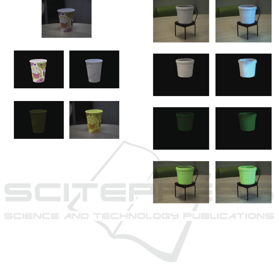
(d) (e)
(a)
(b) (c)
Figure 4: The experimental results using real images: an
object with texture. (a) the input image, (b) the reflectance
of the object, (c) the 3-band spectral irradiance, (d) the flu-
orescent components, and (e) the result image computed by
using our proposed method.
Second, we tested an object with texture as shown
in Figure 4. Figure 4 shows (a) the input image,
(b) the reflectance of the object, (c) the 3-band spec-
tral irradiance, (d) the fluorescent components, and
(e) the result image computed by using our proposed
method. The specified 3-band absorption and emis-
sion spectra are the same as the above. We can see
that (d) the fluorescent components and (e) the re-
sult image computed by using our method are photo-
metrically consistent with the input image; the object
is illuminated almost uniform ambient light. Since
our method makes use of the 3-band spectral irradi-
ance estimated via intrinsic image decomposition, the
computed fluorescent components are not contami-
nated by the texture on the object surface.
Third, we tested an object illuminated by an ad-
ditional light source as shown in Figure 5. Figure 5
shows (a) the input image of an object illuminated
by ambient light and (e) that illuminated by ambient
light and an additional bluish light source from right.
(b)/(f), (c)/(g), and (d)/(h) are the 3-band spectral irra-
diance, the fluorescent components, and the result im-
ages computed from (a)/(e) the corresponding input
images by using our proposed method. The specified
3-band absorption and emission spectra are the same
as the above. We can observe the photometrically
consistent effects of the additional light source in (f),
(g), and (h). Specifically, the 3-band spectral irradi-
(a)
(b)
(c)
(d)
(h)
(g)
(f)
(e)
Figure 5: The experimental results using real images: an
additional light source. (a) the input image of an object il-
luminated by ambient light and (e) that illuminated by am-
bient light and an additional bluish light source from right.
(b)/(f), (c)/(g), and (d)/(h) are the 3-band spectral irradiance,
the fluorescent components, and the result images computed
from (a)/(e) the corresponding input images by using our
proposed method.
ance becomes bluish due to the bluish additional light
source, and therefore the fluorescent components at
the right areas become brighter since the specified flu-
orescent material absorbs bluish light.
4 CONCLUSION
In this paper, we proposed a method for making re-
flective objects in a single input image fluorescent by
adding photorealistic fluorescent components to the
objects of interest. Specifically, we show that photo-
metrically consistent fluorescent components can ap-
proximately be represented by using the 3-band spec-
tral irradiance on the surface of a reflective object, and
then compute the fluorescent components on the ba-
Image-based Material Editing for Making Reflective Objects Fluorescent
359

sis of intrinsic image decomposition without explic-
itly estimating the object’s shape and the light sources
illuminating it from the input image. We conducted
a number of experiments using both synthetic and
real images, and confirmed that our proposed method
is effective for making reflective objects fluorescent.
Taking specular reflection and inter-reflection compo-
nents in an input image into consideration is one of
the future directions of this study.
ACKNOWLEDGMENTS
This work was partially supported by JSPS KAK-
ENHI Grant Numbers JP18H05011 and JP17H01766.
REFERENCES
Barnard, K. (1999). Color constancy with fluorescent sur-
faces. In Proc. CIC1999, pages 257–261.
Barron, J. and Malik, J. (2015). Shape, illumination, and
reflectance from shading. IEEE TPAMI, 38(7):1670–
1687.
Fu, Y., Lam, A., Sato, I., Okabe, T., and Sato, Y. (2016a).
Reflectance and fluorescence spectral recovery via ac-
tively lit RGB images. IEEE TPAMI, 38(7):1313–
1326.
Fu, Y., Lam, A., Sato, I., Okabe, T., and Sato, Y. (2016b).
Separating reflective and fluorescent components us-
ing high frequency illumination in the spectral do-
main. IEEE TPAMI, 38(5):965–978.
Khan, E., Reinhard, E., Fleming, R., and B
¨
ulthoff, H.
(2006). Image-based material editing. In Proc. ACM
SIGGRAPH2006, pages 654–663.
Koyamatsu, K., Hidaka, D., Okabe, T., and Lensch, H.
(2019). Reflective and fluorescent separation under
narrow-band illumination. In Proc. IEEE CVPR2019,
pages 7577–7585.
Liu, G., Ceylan, D., Yumer, E., Yang, J., and Lien, J.-
M. (2017). Material editing using a physically based
rendering network. In Proc. IEEE ICCV2017, pages
2261–2269.
McNamara, G., Gupta, A., Reynaert, J., Coates, T., and
Boswell, C. (2006). Spectral imaging microscopy web
sites and data. Cytometry Part A, 69A(8):863–871.
Sato, I., Okabe, T., and Sato, Y. (2012). Bispectral photo-
metric stereo based on fluorescence. In Proc. IEEE
CVPR2012, pages 270–277.
Tappen, M., Freeman, W., and Adelson, E. (2005). Re-
covering intrinsic images from a single image. IEEE
TPAMI, 27(9):1459–1472.
Treibitz, T., Murez, Z., Mitchell, G., and Kriegman,
D. (2012). Shape from fluorescence. In Proc.
ECCV2012, pages 292–306.
Wang, Z., Bovik, A., Sheikh, H., and Simoncelli, E. (2003).
Image quality assessment: from error visibility to
structural similarity. IEEE TIP, 13(4):600–612.
Zhang, C. and Sato, I. (2013). Image-based separation
of reflective and fluorescent components using illu-
mination variant and invariant color. IEEE TPAMI,
35(12):2866–2877.
GRAPP 2020 - 15th International Conference on Computer Graphics Theory and Applications
360
