
Open Problems in 3D Model and Data Management
Ren
´
e Berndt
1
, Carl Tuemmler
2
, Christian Kehl
3
, Mario Aehnelt
3
, Tim Grasser
4
, Andreas Franek
5
and Torsten Ullrich
1
1
Fraunhofer Austria Research GmbH, Graz, Austria
2
Fraunhofer IGD, Visual Computing System Technologies, Darmstadt, Germany
3
Fraunhofer IGD, Visual Assistance Technologies, Rostock, Germany
4
Fraunhofer IGD, Interactive Engineering Technologies, Darmstadt, Germany
5
Fraunhofer IGD, Virtual and Augmented Reality, Darmstadt, Germany
Keywords:
Computer Graphics, 3D Data, Collaboration, Data Management, Dependency Management.
Abstract:
In interdisciplinary, cooperative projects that involve different representations of 3D models (such as CAD
data and simulation data), a version problem can occur: different representations and parts have to be merged
to form a holistic view of all relevant aspects. The individual partial models may be exported by and modified
in different software environments. These modifications are a recurring activity and may be carried out again
and again during the progress of the project.
This position paper investigates the version problem; furthermore, this contribution is intended to stimulate
discussion on how the problem can be solved.
1 INTRODUCTION
Recently the combination of software development
and information-technology operations (DevOps) has
become the main-stream solution that is adopted by
the software development industry, being able to re-
duce the time-to-market and costs while improving
quality and ensuring extendibility and adaptability
of the resulting software architecture (Capizzi et al.,
2019).
In-a-nutshell, DevOps is a combination of (ag-
ile) mindsets, best practices and tools to reduce time
and complexity when providing applications and ser-
vices (Leite et al., 2020). The core of DevOps is to
overcome the (usually strict) separation between de-
velopment and operation. The main advantages of the
DevOps culture are:
• rapid deployment,
• fast delivery of results to the customer,
• short innovation and product release cycles,
• reliability, and
• scalability.
While the advantages of DevOps are widely con-
firmed by a large number of success stories in real
applications, the handling of 3D data still provides a
show-stopper. In this article, we collect and discuss
the missing pieces for a successful DevOps process-
ing when 3D data is part of a software project, e.g., the
creation of a virtual reality (VR) application for vir-
tual planning based on computer-aided design (CAD)
data.
In such an interdisciplinary, cooperative scenario,
different 3D models have to be merged to form an
overall model with a holistic view of all relevant as-
pects. The individual parts may be exported by and
modified in different software environments. A non-
exhaustive list of modifications includes:
• the repositioning of a submodel in a global coor-
dinate system,
• the reduction of a detailed, partial model to the
relevant aspects in the overall view,
• the creation of different resolutions for interactive
environments,
• the replacement of geometry; e.g., static 3D ge-
ometry may be replaced by animated elements,
• the enrichment of geometry; e.g., addition of con-
text according to the application purpose,
• the adaptation of lighting to different lighting
models, and
• the change of the materials.
Berndt, R., Tuemmler, C., Kehl, C., Aehnelt, M., Grasser, T., Franek, A. and Ullrich, T.
Open Problems in 3D Model and Data Management.
DOI: 10.5220/0009106403470354
In Proceedings of the 15th International Joint Conference on Computer Vision, Imaging and Computer Graphics Theory and Applications (VISIGRAPP 2020) - Volume 1: GRAPP, pages
347-354
ISBN: 978-989-758-402-2; ISSN: 2184-4321
Copyright
c
2022 by SCITEPRESS – Science and Technology Publications, Lda. All rights reserved
347

In particular, the modification of materials involves
many of the previously mentioned geometric prob-
lems in a similar form:
• exchange of materials; e.g., transparent materials
may be replaced by corresponding glass shaders,
• supplement materials; e.g., CAD software may
focus on functional aspects and does not always
define and export (renderable) materials,
• modification of materials; e.g., in the context of
geometry simplification, normal maps are created,
among other things.
These modifications transform a reference model into
a derived model that can be inserted into an overall
model. Within a 3D software project, the reference
model may constantly be developed, expanded and
changed. If the 3D model is a so-called reference
model, each update on the reference model has to be
applied on the derived models as well. During the
complete 3D life cycle, these modifications have to
be iteratively repeated for changing reference models.
With these transformations, even a simple process be-
comes complex as illustrated in Figure 1.
Figure 1: If the 3D model (and all its versions) is a reference
for derived models, then all modifications on the reference
lead to necessary updates on the derived versions.
These manual update processes on 3D data can be ex-
perienced in many contexts.
In the collaborative environment of an architec-
tural office several partners and departments are in-
volved in the planning of a building. The differ-
ent planning aspects (from urban planning and traffic
planning to statics and building services engineering)
are implemented in different software environments,
so that 3D/CAD/BIM/. . . data have to be merged to
form an overall view. In detail, for architectural de-
sign and energy planning, a derived energetic simula-
tion model is created and updated parallel to the BIM
reference model.
Another example is product design: the visually
appealing processing of data always requires the addi-
tion of elements that are not contained in the original
plan, e.g., people in an architectural visualization or a
show room around a car, etc. Despite the addition of
geometry, the opposite requirement is also a frequent
necessity. For the representation in VR environments,
on smartphones, etc. it is often necessary to reduce
the models.
These two exemplary examples serve the purpose
of illustration and stand for many similar situations in
which the versioning problem occurs.
2 RELATED WORK
Digital cross-organizational and cross-border col-
laboration are emerging research issues. Signifi-
cant drivers of this development are collaboration-
related information systems (Madlberger and Roz-
tocki, 2009).
2.1 Collaboration on Text-based Data
The processing of pure text is the most advanced
in respect of cooperation. The handling of text has
evolved through librarianship: Indexing, markup and
retrieval characterize the functional aspects of a li-
brary. These tasks can be considered as practically
solved. Research on metrics and similarity mea-
sures (Gomaa and Fahmy, 2013), on distributed syn-
chronization (Attiya et al., 2016), and on natural lan-
guage processing (Volkart et al., 2018) has made sig-
nificant progress in recent years. Since source code
is usually text-based, the same techniques can also be
used in software development.
2.2 Synchronization Tools for
Relational Databases
Databases typically undergo several schema changes
during their life cycle due to performance and
maintainability reasons. Research on how to sup-
port schema evaluation and migration within the
DevOps culture has made significant progress re-
cently (de Jong et al., 2017). Especially with the trend
to cloud-based micro services, different tool chains
exist for supporting continuous database deployment,
e.g., Microsoft’s Entity Framework Migration.
2.3 Collaboration on 3D Data
Since many 3D file formats and representa-
tions (Schinko et al., 2017) exist that are based
on simple text files, one could naively assume that
GRAPP 2020 - 15th International Conference on Computer Graphics Theory and Applications
348

the text-based approaches mentioned above are also
possible for 3D data. Unfortunately, this is not
possible for several reasons.
• The 3D structure is often represented by a (scene)
graph. Different serializations of the same graph
may result in files with different node order; i.e. a
simple load-and-save-as action without any mod-
ification may result in two files, whose equality
cannot be seen with a text-based diff tool.
• The equality problem is also reflected within
the individual nodes of a scene graph: a non-
uniformal rational B-spline (NURBS) data struc-
ture can also represent B
´
ezier and B-Spline data
(without data loss); for this reason some appli-
cations do not implement separate B
´
ezier and
B-Spline data structures. Once converted to
NURBS, most programs can not recognize that a
patch may “only” be a B
´
ezier or B-Spline patch.
• If a geometric structure cannot be represented in
an equivalent data structure, many programs per-
form a tessellation, which is not reversible.
• The equality problem also exists on the “low-
est” level: floating-point numbers can be repre-
sented in different formats (float/double) and
are not always unique even within one represen-
tation (0.0 vs. -0.0).
These problems and also the distributed synchroniza-
tion problem (Sun and Chen, 2002), (Fuh and Li,
2005) can be solved as long as all participants work
with the same, centralized system. In reality, however,
it is very rare to work with only one application suite,
so that file conversions (with intentional and uninten-
tional geometric modifications) are on the agenda.
3 PROBLEM CLASSIFICATION
3.1 File Formats
Already in 2007 Havemann & Fellner addressed the
absence of a single, commonly accepted, comprehen-
sive 3D file format (Havemann and Fellner, 2007).
With the (still growing) zoo of different file formats
for 3D data, the common denominator is often to use
the most basic ones (e.g., OBJ – although interpre-
tations of MTLs may vary, STL, PLY), while more
mature exchange standards such as STEP (the Inter-
national Standard for the Exchange of Product Model
Data) and IGES (the Initial Graphics Exchange Speci-
fication) are so comprehensive and elaborate that for a
software company to support them (to some degree) is
a predicate of excellence in itself. The vendors of the
most popular 3D tools, which generally use their own
proprietary file formats, have included and developed
various tools and services to support the “complete”
3D processing pipeline in order to keep users within
their ecosystem. The open question here is, how to
encourage these vendors to support and implement a
new file format? In the context of building informa-
tion management (BIM) this was enforced by the re-
quirement of using BIM in open formats (by Indus-
try Foundation Classes, IFC) for all projects of pub-
lic clients. An overview of BIM policies and legal
requirements in the different countries of the EU is
listed in the “European Construction Sector Observa-
tory – Trend Paper – Building Information Modelling
in the EU construction sector (March 2019)”.
A different approach for data exchange is de-
scribed by (Berinstein et al., 2014): “There are also
cases where it makes sense to use a specific 3D pack-
age format if you need specific features not available
in exported file formats. There is, however, a consid-
erable amount of work required to support those file
formats, and we do not recommend them at all. If you
really want to work directly with 3ds Max or Maya,
use the built-in scripting abilities and export exactly
what you need in your own format.”
This gives the consuming application the ability to
use all features the tools offer in order to get the in-
formation needed for the further processing. One ex-
ample is MeshlabXML, which extends Meshlab with
a Python scripting interface. The caveats of the API
approach are that (i) you need the software in order
to process your requests, i.e. you may need additional
licenses and/or hardware, and (ii) it transfers the prob-
lem of supporting many different file formats to sup-
porting many different APIs.
3.2 Different Semantic Interpretations
Although BIM and IFC were previously mentioned as
positive examples, they also illustrate the problem’s
complexity: a building’s design, planning, construc-
tion, operation and deconstruction involves a large
number of crafts, and thus an even larger number of
software environments that have to communicate with
each other. The mere exchange of data from the over-
all model to the energy model is an ongoing research
issue (Chen et al., 2018). The question of data han-
dling of information that is only required by one as-
pect is still open. Should this data be included in
a holistic model, or should a persistent reference be
used? Both approaches lead to new problems; i.e.,
the supplementary information problem and the per-
sistent naming problem.
Open Problems in 3D Model and Data Management
349
3.3 Context-based Supplementary
Information
In the domain of physical simulations, the physical
parameters, such as Young’s modulus, stress tensors
for stress-load simulation, distributions of external
forces and affiliation of vertices to vertex groups for
multi-point constraints, are the required contextual in-
formation. Those change considerably for each vertex
position of the geometry in each new simulation case.
On the other hand, for the purpose of comparability,
the geometric structure commonly stays fixed for sim-
ulations within the same series.
In the realm of augmented reality applications, the
geometrically-derived tracking information are vital
for the working of the system. How those tracking
information are represented depends majorly on the
tracking algorithm. As an example, feature point-
based tracking requires the selection of prominent
vertices within the geometry that are unambiguous
in their view projection and, thus, are stable track-
ing candidates. In image-based tracking approaches,
the scene components that are the tracking focal tar-
get need to be selected to reduce the loss of tracking
paths and speed-up convergence. In either case, the
geometric and tracking information need to be kept
up-to-date on changes of the base geometry.
For the visualization and digital design of engi-
neering products, ranging from manufactured goods
over vehicles to production plants, the data itself usu-
ally contains so-called Product Manufacturing Infor-
mation (PMI) data. This additional data helps visual-
ize important measurements from defined views, for
example, see Figure 2. A data set can define many
such measurements and associate these with defined
views, allowing users to switch between the views to
only see relevant information for each view.
Figure 2: A dataset may have product manufacturing in-
formation (PMI) associated to and only visible in certain
views.
The interoperability between different 3D data pro-
ducer and consumer systems, such as tools for CAD
modeling, geometric (post-)processing, physical sim-
ulation and visualization, is affected by the way con-
text information are stored and exchanged. Many
graphics systems are organized in a graph structure,
in which additional data can be stored in nodes. Al-
ternatively, they are organized in so-called “fat” data
structures – often encountered in volumetric simu-
lations – where all supplementary information, e.g.,
color, physical attributes, group adherence, etc. is at-
tached to each individual geometric element (face, tri-
angle, polyhedron, . . . ). Irrespective of the data struc-
ture used, however, it shall be possible to manage any
additional data sensibly. As long as programs simply
discard or ignore unknown data and attributes, this in-
formation gap is not closed and the problems in pre-
serving the coherence of context information across
multiple processing systems is not solved.
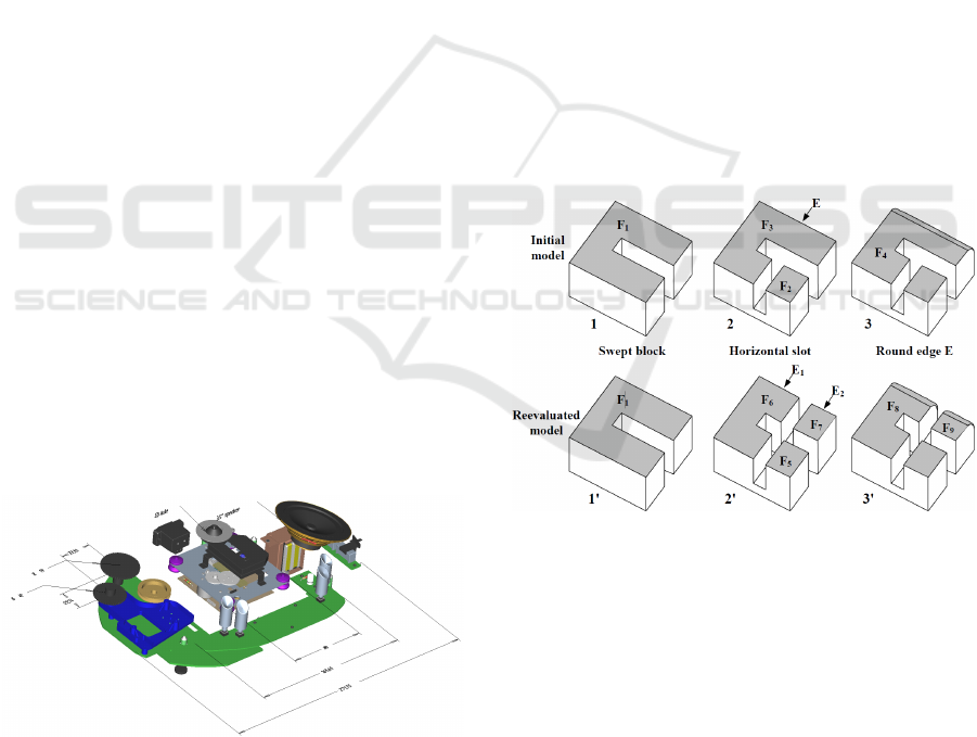
3.4 Persistent Naming Problem
An important problem in computer-aided design is
the persistent naming problem (Marcheix and Pierra,
2002). The problem occurs in the context of para-
metric and generative modeling (Krispel et al., 2016),
namely whenever entities are referenced that are the
result of an algorithmic evaluation.
Figure 3: In this example an initial model is designed by
means of a parametric specification containing four succes-
sive constructive steps. The fourth one consists of rounding
edge e. During re-evaluation at step 3’, the edge e has been
split into two edges e
1
and e
2
. As a consequence, at step 4’
the problem is to determine which edge or edges have to be
rounded. The problem is to identify, i.e. to match, edge e
with edges e
1
and e
2
despite topology changes.
Image source: (Marcheix and Pierra, 2002).
Referenced entities must then be named in a persistent
way in order to be able to re-evaluate the model in a
consistent manner. Figure 3 illustrates the problem.
GRAPP 2020 - 15th International Conference on Computer Graphics Theory and Applications
350

3.5 Different Geometry Representations
In simplified terms, CAD representations are well
suited for modelling; tessellations are used for visual
representations; and volumetric models are needed
for simulation purposes (Schinko et al., 2017). Hence,
in a cooperative, interdisciplinary project, conver-
sions are inevitable. Since model transformation is
a challenging task, a wide range of algorithms and
implementations have been developed. They can be
parametrized according to
• the resulting element quality and
• the input resolution adequate to the given prob-
lem,
• the interpretation of the input geometry, and ac-
cording to
• parameters specific to the given conversion algo-
rithm.
Due to these dependencies, a fully automatic conver-
sion is usually not possible. Because of the time con-
suming challenge of choosing the best parameters, a
full documentation of the process is required in order
to allow for efficient adaptations of the generated ge-
ometry. A documentation of the process may include
the used algorithm and the version of its implemen-
tation, the specified parameters and in some cases in-
formation about required modifications to the given
input object. A non-automated solution therefore re-
quires not only the effort that would be replaced by
automation, but also additional documentation effort.
3.6 Third-party Software Limitations
In addition to the purely technical problems, other
problems occur when one sets up an automatic pro-
cessing pipeline:
• When using an external library, software engi-
neering problems, such as poor documentation,
limited code readability, source code maintain-
ability issues, etc., are recognized more inten-
sively than with one’s own code.
• A multitude of software licenses and different
licensing models (from public domain via non-
protective licenses and protective licenses to pro-
prietary licenses) pose legal hurdles that can make
it impossible to combine different libraries.
4 APPROACHES
There are currently no generally accepted solutions
for the problems mentioned, but only solution strate-
gies and approaches.
4.1 Continuous Integration
In the context of 3D data pipelines, continuous inte-
gration can be used to reapply a given pipeline when
the ground truth changes, e.g., every time the original
file is updated. This ensures that any derived repre-
sentation always reflects the current state of the orig-
inal dataset. Using this workflow in practice requires
a tight coupling with the data source. Either the data
source triggers the pipeline to run, or the pipeline re-
sults need be abstracted in such a way that it can be
rerun, if required, on access. One way to implement
this approach is a service-oriented architecture. In a
serviced environment, accessing a result always trig-
gers a check against the original dataset before pro-
viding the results. This ensures that consumers of the
service always receive the latest representation.
A real-world example of this workflow in the do-
main of 3D data is instant3Dhub. It provides data
visualization in a web browser, allowing many data
formats to be used. When the system is asked to vi-
sualize a dataset, it transparently converts it to a web-
optimized format. In order to ensure the converted
data is never out of date, every access performs a
check against the data source, and transparently re-
converts it, if the source has changed. As a visual-
ization system, however, this solution is a data sink
in principle, i.e. it represents only the last links in a
processing chain.
4.2 Feedback Loops
An ad-hoc solution to the problem of managing
changes in 3D data is to define project-specific data
and communication standards with collaborators. In
detail, this means that, for example, everyone agrees
on file names with prefixes, that the function of a ge-
ometric group is encoded in its name, etc. As an ex-
ample; to identify parts of the 3D data that should be
enhanced with information that enables visual track-
ing, their node tags could be required to satisfy a reg-
ular expression. In this manner different tracking en-
vironments can be represented, too. The tree structure
could be used to express which parts of the model
should be assumed to occlude parts that are to be
tracked visually. This process can be time consum-
ing, especially if the collaborating parties are not col-
located, communication is time intensive or the data
has to be checked manually.
4.3 Reusability in Software Engineering
How must software be designed so that it can be
reused in new contexts and that it can be used for pur-
Open Problems in 3D Model and Data Management
351
poses that were not known during the software devel-
opment phase? Some answers to this question are as
follows:
• Open-source. If the source code of all programs
in a processing pipeline were openly accessible,
the pipeline could achieve any degree of integra-
tion. But even open-source programs cannot al-
ways be integrated if the effort is not justifiable.
• C-/REST-interface. Via well-defined interfaces,
programs, libraries and services can be integrated
into a processing pipeline – directly or via wrap-
pers. In most cases, the complexity of such a so-
lution correlates with the complexity of the data
structures to be exchanged.
• Plugins. In contrast to “low-level” interfaces like
C or REST, plugin mechanisms offer the possibil-
ity to exchange even complex information; how-
ever, this information exchange is more tied to the
platform (language, environment, etc.) and it is
less flexible. Nevertheless, they are useful, like
the Datasmith plugin for the Unreal Engine to im-
print CAD geometry.
• Scripting. In reality, an increasing number of
integration approaches are used as the length of
the processing pipeline advances. Since, in such
cases, not only the models are often subject to
change, but also the pipeline is being altered, flex-
ibility is of paramount importance. Scripting lan-
guages achieve this flexibility. As a consequence,
more and more libraries and geometry kernels
(CGAL, Open CASCADE, etc.) offer a Python
interface.
For an evaluation of which solution (for future li-
braries to be developed) achieves the highest degree
of reusability, the data basis is currently lacking.
4.4 Persistent Toolbox Environment
Next to plain-scripting, plain-plugin and plain-
wrapper approaches, some systems have chosen an
alternative solution to interface their system’s func-
tionality for external use:
• GraalVM is a universal virtual machine for run-
ning applications written in JavaScript, Python,
Ruby, R, JVM-based languages like Java, Scala,
Groovy, Kotlin, Clojure, and LLVM-based lan-
guages such as C and C++. It removes the isola-
tion between programming languages and enables
interoperability in a shared runtime.
• Complex toolboxes, such as MeshLab (Cignoni
et al., 2008), MatLab and Octave run their own,
shelled runtime environments. A well-know, es-
tablished expression of this context is MatLab’s
MEX environment, which are runtime-interpreted
function commands for MatLab operations for
transparent lower-level programming interfaces to
C, C++ or FORTRAN. Conversely, the execution
of MatLab’s M-files allows to run MatLab-native
functions from anywhere within the application
context and workspace environment.
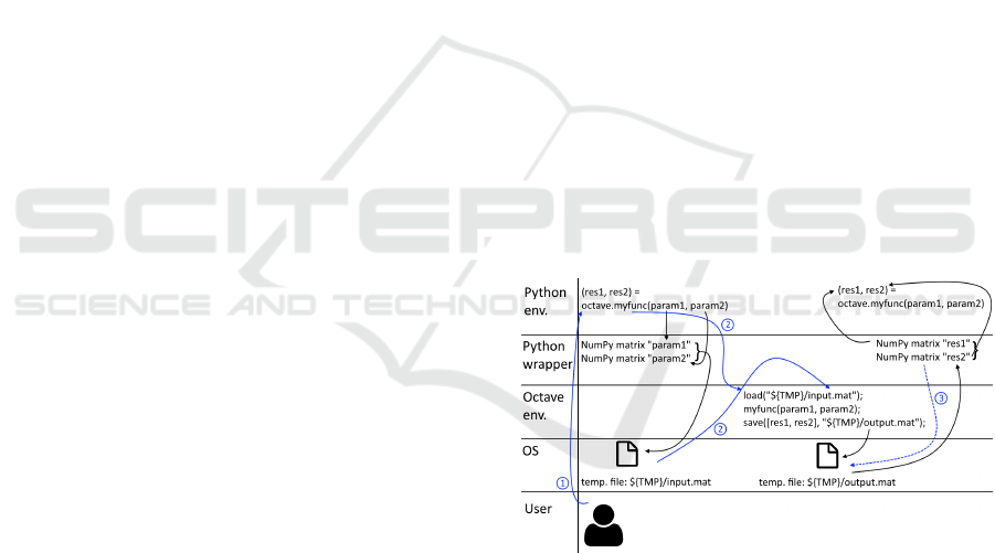
• Recently, the concept of system-wide M-file re-
mote procedure calls (RPC) has been expanded
in Octave’s Python interface Oct2Py, which ex-
poses the full Octave functionality during runtime
system-wide to active Python interfaces. The sys-
tem works as shown in Figure 4: The user re-
quests executing a given Octave function within a
Python environment. The Oct2Py wrapper trans-
forms the data and stores them as temporary files
within the operating system. Then, the Octave in-
struction is invoked in a running Octave instance,
which stores the results on disk after execution.
The Oct2Py Python wrapper picks up the results
and returns them as valid Python data to the user.
In terms of robustness and proficiency, this tool
and architecture has already been used in various
projects, such as the processing and segmenta-
tion of spectral CT scans of airport luggage (Kehl
et al., 2018).
Figure 4: Illustration of the working principle of Oct2Py.
These software architectures can be exploited and ex-
panded for interfacing other persistent-environment
subsystems and third-party toolboxes, such as Mat-
Lab, Blender, or the JT Open Toolkit. These ap-
proaches are a possible way to transfer knowledge and
best-practices across research groups.
5 SUMMARY
A solution for the described problem would have a
huge impact on 3D data processing. Optimizations in
GRAPP 2020 - 15th International Conference on Computer Graphics Theory and Applications
352
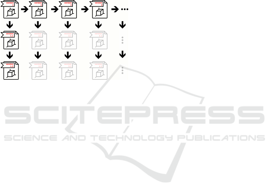
the 3D modeling pipeline enable fast iteration cycles
in the planning and development phase. A complete
automation, i.e. the automatic generation of all de-
rived models, offers many possibilities: the current
planning status would be always visible for a coop-
erative VR meeting – without delay due to manual,
time-consuming model preparation, which means that
the current planning status is never used, but the status
from a few days ago.
Figure 5: The 3D model (and all its derived versions) have
already been shown in Figure 1. This Figure illustrates
the impact of an automatic solution to generate the derived
models. If the grey files can be generated automatically,
even in this toy example the workload can be reduced by
50%.
Figure 5 illustrates the amount of work that may not
be necessary any more. In a non-representative, ad-
hoc survey among project partners, the savings po-
tential was estimated at 25% of the research project
costs in the field of visual computing. The total mar-
ket potential (in Germany) for a functioning solution
can be guessed using the study of (Astor et al., 2013)
which lists around 2 500 enterprises within the value
chain of 3D data processing.
As a consequence, this position paper should
therefore encourage a solution-oriented discussion.
ACKNOWLEDGEMENTS
This work is part of the strategic project “COntinuous
Model Integration Chain (COMIC)” funded by
Fraunhofer.
Furthermore, the authors acknowledge the gen-
erous support of the Carinthian Government and
the City of Klagenfurt within the innovation center
KI4Life.
REFERENCES
Astor, M., Glo
¨
ockner, U., Klose, G., Plume, A.-M., Schnei-
denbach, T., von Lukas, U., Bechtold, I., Ruth, T.,
Jarowinsky, M., and Bartels, H.-J. (2013). Markt-
perspektiven von 3D in industriellen Anwendungen.
Prognos AG, Fraunhofer IGD, MC Marketing Con-
sulting on behalf of the German Federal Ministry of
Economics and Technology.
Attiya, H., Burckhardt, S., Gotsman, A., Morrison, A.,
Yang, H., and Zawirski, M. (2016). Specification
and Complexity of Collaborative Text Editing. ACM
Symposium on Principles of Distributed Computing,
31:259–268.
Berinstein, P., Arnaud, R., Ardolino, A., Franco, S.,
Herubel, A., McCutchan, J., Nedelcu, N., Nitschke,
B., Olmstead, D., Robinet, F., Ronchi, C., Turkowski,
R., Walter, R., and Samour, G. (2014). Game Devel-
opment Tool Essentials. Apress.
Capizzi, A., Distefano, S., and Mazzara, M. (2019). From
DevOps to DevDataOps: Data Management in De-
vOps Processes. The Computing Research Repository,
10:1910.03066.
Chen, S., Jin, R., and Alam, M. (2018). Investigation of
Interoperability between Building Information Mod-
elling (BIM) and Building Energy Simulation (BES).
International Review of Applied Sciences and Engi-
neering, 9:137–144.
Cignoni, P., Callieri, M., Corsini, M., Dellepiane, M.,
Ganovelli, F., and Ranzuglia, G. (2008). Meshlab:
an Open-Source Mesh Processing Tool. Eurograph-
ics Italian Chapter Conference, 3:129–136.
de Jong, M., van Deursen, A., and Cleve, A. (2017). Zero-
downtime SQL Database Schema Evolution for Con-
tinuous Deployment. International Conference on
Software Engineering: Software Engineering in Prac-
tice, 39:143–152.
Fuh, J. Y. H. and Li, W. D. (2005). Advances in Collab-
orative CAD: the-State-of-the-Art. Computer-Aided
Design, 37:571–581.
Gomaa, W. H. and Fahmy, A. A. (2013). A Survey of Text
Similarity Approaches. International Journal of Com-
puter Applications, 68:13–18.
Havemann, S. and Fellner, D. W. (2007). Seven Research
Challenges of Generalized 3D Documents. IEEE
Computer Graphics and Applications, 27:70–76.
Kehl, C., Mustafa, W., Kehres, J., Dahl, A. B., and
Olsen, U. L. (2018). Multi-Spectral Imaging via
Computed Tomography (MUSIC)-Comparing Unsu-
pervised Spectral Segmentations for Material Differ-
entiation. arXiv preprint arXiv:1810.11823.
Krispel, U., Schinko, C., and Ullrich, T. (2016). A Survey
of Algorithmic Shapes. Remote Sensed Data and Pro-
cessing Methodologies for 3D Virtual Reconstruction
and Visualization of Complex Architectures, 219:498–
529.
Leite, L., Rocha, C., Kon, F., Milojicic, D., and Meirelles,
P. (2020). A Survey of DevOps Concepts and Chal-
lenges. ACM Computing Surveys, accepted.
Madlberger, M. and Roztocki, N. (2009). Digital Cross-
Organizational and Cross-Border Collaboration: A
Open Problems in 3D Model and Data Management
353

Scientometric Study. International Conference on
System Sciences, 42:1–10.
Marcheix, D. and Pierra, G. (2002). A Survey of the Per-
sistent Naming Problem. ACM Symposium on Solid
Modeling and Applications, 7:13–22.
Schinko, C., Riffnaller-Schiefer, A., Krispel, U., Eggeling,
E., and Ullrich, T. (2017). State-of-the-Art Overview
on 3D Model Representations and Transformations in
the Context of Computer-Aided Design. International
Journal On Advances in Software, 10:446–458.
Sun, C. and Chen, D. (2002). Consistency Maintenance in
Real-Time Collaborative Graphics Editing Systems.
ACM Transactions on Computer-Human Interaction,
9:1–41.
Volkart, L., Bouillon, P., and Girletti, S. (2018). Statisti-
cal vs. Neural Machine Translation: A Comparison of
MTH and DeepL at Swiss Post’s Language Service.
Translating and the Computer, 40:145–150.
GRAPP 2020 - 15th International Conference on Computer Graphics Theory and Applications
354
