On the Fly Vehicle Modeling and Tracking
with 2D-LiDAR Detector and Infrared Camera
Kazuhiko Sumi
1
a
, Kazunari Takagi
1
, Tatsuya Oshiro
2
, Takuya Matsumoto
2
, Kazuyoshi Kitajima
3
,
Yoshifumi Hayakawa
3
and Masayuki Yamamoto
3
1
Aoyama Gakuin University, Fuchinobe Honmachi, Sagamihara, Japan
2
Sohatsu System Laboratory, Kobe, Japan
3
Mitsubishi Heavy Industry Machinery Systems LTD, Kobe, Japan
Keywords:
Vehicle Detection, Vehicle Tracking, Localization, Infra-Red, Lidar.
Abstract:
We propose a vehicle detection and tracking system that tracks vehicles from the rear using a 10-band infrared
(IR) surveillance camera installed along the expressway. The main reason for using an infrared camera is to
suppress the strong light reflections of head and tail lights of the vehicle at rainy night. However, due to lack
of a large IR traffic video datasets covering all type of vehicles, we will not be able to take advantages of
recent machine learning advances. Therefore, we propose rather straight approach to detect vehicles by a pair
of 2D-LiDARs, then generate the image model of vehicle to be tracked on the fly. We prototyped the system
and evaluated it with a normal traffic video taken on a highway. We achieved a 94% tracking success rate at a
distance of 20m to 70m from the camera and mean error of localization is less than 2m at 70m.
1 INTRODUCTION
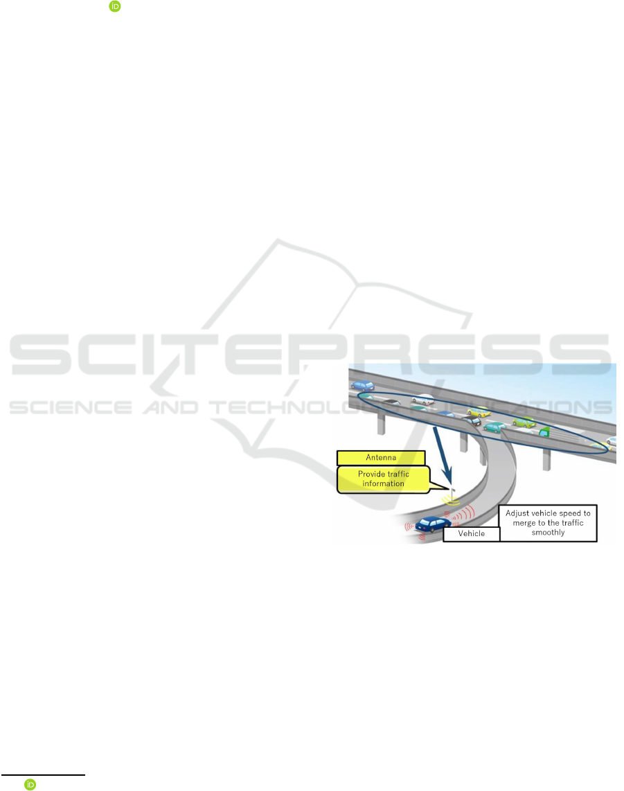
In Japan, in order to support driving operations where
autonomous vehicles join on highways, the position
and speed of traveling vehicles on the main line are
recognized as road infrastructure, and on the main
road A service is planned to provide information on
the position and speed of the vehicle before entering
the sensor field of the autonomous vehicle. (See Fig-
ure 1) Several methods are conceivable for realizing
the vehicle localization in this system. The first op-
tion is sensor selection: (a) camera, (b) LiDAR, or
(c) millimeter wave radar. The second option is sen-
sor location: (e) measuring a vehicle from front or
(f) tracking from the rear. The third is algorithm and
object modeling. For example, if a visible camera is
chosen, various algorithms and object models are pro-
posed (Al-Smadi et al., 2016).
Regards to the sensor selection, LiDAR has an ad-
vantage that the distance of the point scanned can be
directly measured. 3D-LiDAR is the most popular
sensor for autonomous driving. On the other hand, for
this application, LiDAR has disadvantages in measur-
ing a vehicle behind another one due to its sparse spa-
tial sampling. On the other hand, camera is suitable
a
https://orcid.org/0000-0002-9165-5912
Figure 1: Concept of autonomous vehicle support system at
expressway junction.
because camera has the best spatial resolution and this
enables recognizing each vehicle in a row of consec-
utive cars. The next question is the detection algo-
rithm. So far, successful algorithms includes back-
ground subtraction (Seki et al., 2003), optical flow
(Chen and Wu, 2015), HOG like features (Wei et al.,
2019), and deep learning based approach (Scheideg-
ger et al., 2018).
Currently, most of the surveillance cameras in-
stalled on the road use RGB cameras to make it easier
for humans to observe. However, RGB camera im-
ages are extremely hard to be correctly segmented by
810
Sumi, K., Takagi, K., Oshiro, T., Matsumoto, T., Kitajima, K., Hayakawa, Y. and Yamamoto, M.
On the Fly Vehicle Modeling and Tracking with 2D-LiDAR Detector and Infrared Camera.
DOI: 10.5220/0009105608100813
In Proceedings of the 15th International Joint Conference on Computer Vision, Imaging and Computer Graphics Theory and Applications (VISIGRAPP 2020) - Volume 4: VISAPP, pages
810-813
ISBN: 978-989-758-402-2; ISSN: 2184-4321
Copyright
c
2022 by SCITEPRESS – Science and Technology Publications, Lda. All rights reserved
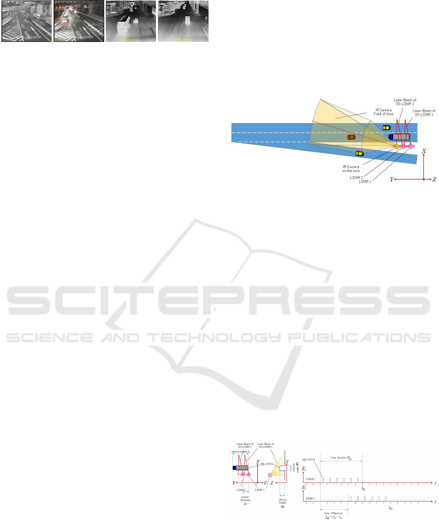
Figure 2: Comparison of day and night image in RGB cam-
era and IR camera. From the left to right: RGB daytime,
RGB night, IR daytime, IR night. Note that appearance
of RGB image changes drastically between night and day.
Vehicle segmentation becomes extremely hard in the rainy
night.
computers (Bahnsen and Moeslund, 2018). So, we
decided to use a 10m band IR camera this time. Us-
ing an IR camera eliminates the effects of strong light
reflections on the wet surface as well as suppressing
the direct light from the vehicle’s head and rear lights.
However, this time, the following technical issues
arise.
• Compared to RGB images, IR images reflect ve-
hicle heat at the road surface, so afterglow is ob-
served around the vehicle. Therefore, it is difficult
to separate only the vehicle by background differ-
ence.
• IR cameras are not often installed on the road, and
IR image learning data sets cannot be obtained.
Therefore, the method of learning HOG features
(requires thousands to tens of thousands of anno-
tated image data) and Deep Learning methods (re-
quires tens of thousands to millions of annotated
image data) cannot be obtained, and the detector I
can’t learn.
• On actual roads, there are cases that cannot be
covered by standard data sets, such as variations
in truck loading, towed trailers, and rarely used
special vehicles.
• Compared to RGB images, IR images have many
components with low spatial frequency, so there
are fewer key points for image feature descrip-
tors such as SIFT and ORB. Therefore, keypoint-
based tracking is difficult to perform.
• The IR image is a 1-band image, and a color his-
togram cannot be created. Therefore, it is difficult
to apply Mean-shift and MCMC, which are track-
ing methods featuring color histograms.
In order to overcome these problems, we make the
following proposals.
1. Vehicle tracking is performed using IR images.
The input image is a 1-band IR image, and the
vehicle model is an image model obtained by cut-
ting out the rear end region of the vehicle from the
IR image taken on the spot.
2. Tracking in successive images is done by search-
ing for the point where the normalized cross-
correlation with the vehicle model image is maxi-
mized.
3. To accurately determine the rear end of the ve-
hicle, measure the width, height, length, and
speed of the vehicle using two 2D-LiDARs. After
passing through 2D-LiDAR, which frame Predict
whether the rear end of the vehicle will appear at
the position.
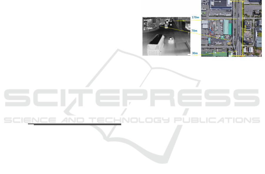
Figure 3: Concept of our vehicle detection and tracking sys-
tem — arrangement of sensors.
2 VEHICLE DETECTION
The geometrical layout of 2D-LiDAR, roads and ve-
hicles is shown in the figure 3. Here, one LiDAR ac-
quires the cross-sectional shape of the road and the
vehicle by a laser beam that rotates and scans from the
center of the sensor as shown in the figure 4. In the
figure, the reference position of vehicle i passing at
time t = t1 is the coordinates of the lower left corner
of the rear end of the ith vehicle. Vehicle width W
i
,
height H
i
are obtained from a single scan waveform
as shown in the middle of figure 4. Vehicle speed
along Y axis v
yi
is obtained by v
i
= D/T
di
, where D
is the distance between two 2D-LiDARs. The vehicle
length L
i
is obtained by L
i
= DT
Li
/T
di
. In practice, the
vehicle is not a rectangular but has an uneven height
profile. Therefore, the vehicle cross-sectional shape
W
i
and H
i
are measured at the rear end of the vehicle.
Figure 4: Principle of vehicle detection and measurement.
3 MODEL CREATION AND
TRACKING
Following the detection of the vehicle, the vehicle ap-
On the Fly Vehicle Modeling and Tracking with 2D-LiDAR Detector and Infrared Camera
811
pears in the IR camera, so a vehicle model for tracking
the vehicle is generated on the spot. In our proposed
system, tracking uses the cross-correlation peak be-
tween the vehicle model image and the image being
tracked, so the vehicle model is the area surrounding
the vehicle in the video. It should be noted here that
the appearance of the vehicle changes during track-
ing. The cause of the apparent change is a geometric
change due to the rotation of the vehicle and the per-
spective projection of the camera, and a change of the
maid pattern due to the optical environment change.
Our tracking target is assumed to be a straight high-
way, and the geometric change due to the rotation of
the vehicle is small, but in order to track from 20m
to 140m far from the camera, the geometric change
due to perspective projection is Must be considered.
In the case of an IR camera, the pixel value is not an
absolute amount of heat radiation, but is obtained as
a relative value with respect to the surrounding pixel
values, so that the gain and offset of the luminance
pattern are not unchanged. For this reason, the ve-
hicle model uses a pattern on the rear end surface of
the vehicle that is nearly perpendicular to the camera
optical axis with little change in shape in perspective
projection from near to far. Use of zero-mean normal-
ized cross-correlation has the advantage that changes
in gain and offset do not affect the correlation value.
Note that vehicle model (template image) should be
shrinked as the vehicle moves away.
q(u,v) =
∑
x,y
T
i
(x,y) · (I(u+ x,v+ y) −
¯
I)
q
∑
x,y
T
i
(x,y)
2
∑
x,y
(I(u + x, v+ y) −
¯
I)
2
(1)
where q(u,v), I(u,v),
¯
I, T
i
(x,y) and
¯
T are the simi-
larity score at image location u,v, the image value at
location u,v, the mean of I(u, v), the model (template)
value, and the mean of T(x,y) respectively. Note that
T is adjusted so as to
¯
T = 0.
A new tracking location in the i-th image is given
by the following equation:
x,y = arg max
x,y
q
x,y
(2)
4 EXPERIMENTS AND
DISCUSSION
The proposed system was prototyped and its perfor-
mance was evaluated on a highway. The system was
setup over a four-lane highway in Kobe City’s Mi-
natojima, where sensors and cameras are temporarily
placed on a pedestrian bridge that crosses the road,
data is acquired and saved in a file system, and the
evaluation was done off-line. The tracking success
rate and the accuracy was verified. The IR cam-
era was a traffic surveillance camera made by FLIR
(image resolution 640 x 480 pixels, wavelength 10
mm), and the 2D-LiDAR was make by SICK. Fig-
ure 5 shows the correspondence between the scene of
the test site as seen from the aerial photograph and
the image taken with the IR camera. From a few tens
of minutes of video taken on this site, 100 vehicles
were selected randomly, and the rear end position of
each vehicle in each frame was manually marked as
the ground truth.
Figure 5: Captured image of the test site and the corre-
sponding aerial photo. (taken from Google map).
Figure 8 shows the tracking success rate with re-
spect to the distance from the camera. Tracking suc-
cess is the apparent tracking (Figure, red line) where
the tracking is continued in the algorithm, and the true
success rate (Figure, blue line) being tracked within
a certain range of error from the ground truth. A
tracking failure of several percent was observed near
the distance from the camera exceeding 70m, and in-
creased to about 20% at 150m, which ended the track-
ing. From this, it can be concluded that this system
can track up to a distance of 70m from the vicinity of
the camera with high reliability. There is also a 3%
tracking failure from close to 70m. The reason is that
the initial model (template) was generated almost cor-
rectly, but the search failed in the next frame. This is
considered to be because the template magnification
prediction in the next frame has failed, and it is esti-
mated that there is an algorithmic problem in the por-
tion that predicts the template magnification through
the velocity measurement and map-to-camera coordi-
nate conversion matrix.
5 CONCLUSION AND FUTURE
WORK
Our proposal demonstrates the effectiveness of on-
the-fly vehicle model generation with vehicle detec-
tion using LiDAR. So far, a data set that enables IR
vehicle image tracking only from images has not been
VISAPP 2020 - 15th International Conference on Computer Vision Theory and Applications
812
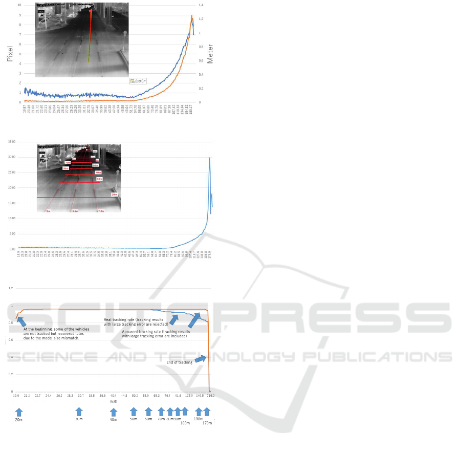
Figure 6: Error analysis in horizontal axis.
Figure 7: Error analysis in distance axis.
Figure 8: Successful tracking rate.
developed, and this method is considered to be op-
timal at present. However, there is an initial track-
ing failure rate of 3%, and tracking position accuracy
drops from around 70m, and at 150m, 17% of cases
where initial tracking is successful are considered to
be miss-tracked. The development of better methods
is required before practical use. Analysis of failure
cases reveals that the major cause of miss-tracking
is that the vehicle being tracked is concealed by the
following vehicle. We plan to develop more sophisti-
cated algorithms, such as a tracking method that pre-
dicts the vehicle position when it is completely con-
cealed, and a method that restores tracking when it
reappears. On the other hand, it is important to install
this system in the real environment as soon as pos-
sible and experience many cases. At present, prob-
lems that are not frequently understood should be dis-
covered and algorithms should be improved. Further-
more, this system can contributeto the creation of ma-
chine learning data sets. If LiDAR is installed at mul-
tiple locations, correct values can be automatically as-
signed in image tracking, and large-scale data sets can
be constructed using them. In the near future, it is ex-
pected that feature points suitable for IR image vehi-
cle detection and tracking can be learned with just a
camera without using LiDAR vehicle detection.
REFERENCES
Al-Smadi, M., Abdulrahim, K., and Abdul Salam, R.
(2016). Traffic surveillance: A review of vision based
vehicle detection, recognition and tracking. 11:713–
726.
Bahnsen, C. H. and Moeslund, T. B. (2018). Rain removal
in traffic surveillance: Does it matter? IEEE Trans-
actions on Intelligent Transportation Systems, pages
1–18.
Chen, Y. and Wu, Q. (2015). Moving vehicle detection
based on optical flow estimation of edge. In 11th
International Conference on Natural Computation,
ICNC 2015, Zhangjiajie, China, August 15-17, 2015,
pages 754–758.
Scheidegger, S., Benjaminsson, J., Rosenberg, E., Krish-
nan, A., and Granstr¨om, K. (2018). Mono-camera 3d
multi-object tracking using deep learning detections
and PMBM filtering. In 2018 IEEE Intelligent Vehi-
cles Symposium, IV 2018, Changshu, Suzhou, China,
June 26-30, 2018, pages 433–440.
Seki, M., Wada, T., Fujiwara, H., and Sumi, K. (2003).
Background subtraction based on cooccurence of im-
age variations. volume 2, pages II–65.
Wei, Y., Tian, Q., Guo, J., Huang, W., and Cao, J. (2019).
Multi-vehicle detection algorithm through combining
harr and hog features. Mathematics and Computers in
Simulation, 155:130 – 145. International Conference
on Mathematical Modeling and Computational Meth-
ods in Science and Engineering.
On the Fly Vehicle Modeling and Tracking with 2D-LiDAR Detector and Infrared Camera
813
