
Early Synthesis of Timing Models in AUTOSAR-based Automotive
Embedded Software Systems
Padma Iyenghar
a
, Lars Huning and Elke Pulvermueller
Research Group Software Engineering, University of Osnabrueck, Germany
Keywords:
Model-based Timing Analysis, Unified Modeling Language (UML), AUTOSAR, Embedded Software.
Abstract:
Development of AUTOSAR-based embedded systems in Unified Modeling Language (UML) tools is an
emerging state-of-the-art practice in the automotive industry. In case of such automotive systems with strict
timing requirements (e.g. advanced driver assistance systems), not only the correctness of the computation
results is important, but also their timeliness. This necessitates comprehensive and early verification and
validation procedures to ensure desired software quality without overshooting the budget. The main input
required for such timing analysis, in specialized timing analysis tools, is the AUTOSAR-timing model corre-
sponding to the timing annotated AUTOSAR-design model. Thus, synthesis of such a timing analysis model
from AUTOSAR-based design model (developed in UML tools), early in the development stages, constitutes
an important step and a research gap. Towards this direction, this paper presents a systematic approach for
extraction and synthesis of timing analysis model from AUTOSAR-based embedded system design models
developed in UML tools. A prototype of model transformations for the synthesis of timing models and its
evaluation in an automotive use case are presented.
1 INTRODUCTION
In the recent decade, model-based techniques have
become important to conquer the development com-
plexity in large embedded projects such as modern
cars. They provide systematic, cost-effective develop-
ment processes which help reduce time-to-market and
development costs, whilst enhancing software qual-
ity (Navet and Simonot-Lion, 2009). Models of the
software and hardware architecture can be reused in
multiple development phases to automate the process,
e.g. by generating code from a design model. Ideally
this not only saves time, but also reduces human er-
rors and bugs in the production code. Thus, for auto-
motive embedded software rich in safety-critical and
timing functions, it is imperative to integrate timing
validation into the model-based development process
as early as possible.
By standardizing the model-based techniques, the
players in the industry can settle on best practices and
further refine and streamline the embedded software
development process. The AUTomotive Open Sys-
tem ARchitecture (AUTOSAR) initiative is an effort
to standardize the software architecture of automo-
a
https://orcid.org/0000-0002-1765-3695
tive electronic systems (AUTOSAR, 2018). Its main
goal is to introduce a standardized layer between ap-
plication software and the hardware of an Electronic
Control Unit (ECU)
1
. Thus, the software is largely in-
dependent from any chosen microcontroller and car
manufacturer, making it reusable for several individ-
ual ECU systems.
The AUTOSAR Timing Extensions (TE) is a
standardized formal timing model to capture tim-
ing constraints of automotive systems (AUTOSAR,
2018). With this, it is possible to include the sys-
tem’s timing behavior already in the design models.
The AUTOSAR timing language (Artime)
2
(Sche-
ickl et al., 2012) supports a formal specification of
timing descriptions using a textual representation of
the AUTOSAR TE. On the other hand, development
of AUTOSAR-based embedded systems in Unified
Modeling Language (UML)
3
tools (IBM Software,
2019) is a state-of-the-art practice in the automotive
industry. Thus, it is intuitive to perceive that mod-
eling timing requirements using AUTOSAR-TE in
AUTOSAR-based design models in UML tools and
1
An embedded system that controls one or more of the
electrical systems or subsystems in a vehicle.
2
https://www.artop.org/
3
https://www.uml.org/
26
Iyenghar, P., Huning, L. and Pulvermueller, E.
Early Synthesis of Timing Models in AUTOSAR-based Automotive Embedded Software Systems.
DOI: 10.5220/0009095000260038
In Proceedings of the 8th International Conference on Model-Dr iven Engineering and Software Development (MODELSWARD 2020), pages 26-38
ISBN: 978-989-758-400-8; ISSN: 2184-4348
Copyright
c
2022 by SCITEPRESS – Science and Technology Publications, Lda. All rights reserved

analysis of AUTOSAR timing models in specialized
timing analysis tools (INCHRON, 2019), (Luxoft –
Symtavision, 2019) is the step forward in the automo-
tive development processes.
Validating the timing behavior and checking for
adherence to real-time constraints in early design
stages could save costly corrections of potential errors
in the design of the system (Navet and Simonot-Lion,
2009). For this purpose, the timing requirements
specified in the design model have to be translated
and a timing analysis model needs to be synthesized.
This model can then be provided as input to a timing
analysis tool for validation. To achieve this step at an
early point in the developmental stages, an early syn-
thesis of timing models from the AUTOSAR-based
UML design model is necessary.
In this context, a timing metamodel for synthesis
of a timing analysis model from timing annotated de-
sign models is proposed in (Iyenghar et al., 2016).
This work deals with time modeling in generic em-
bedded software development using UML. The work
presented in (Iyenghar and Pulvermueller, 2018), ex-
tends the timing metamodel in (Iyenghar et al., 2016)
with energy properties and proposes energy-aware
timing analysis for IoT use cases. Though these re-
lated work deal with timing analysis, they do not deal
with AUTOSAR-based development and timing mod-
eling. Addressing this gap, this paper presents the fol-
lowing novelties:
1. A systematic series of steps towards extrac-
tion and synthesis of timing analysis models in
AUTOSAR-based embedded system design mod-
els (which are developed in UML tools).
2. Mapping of AUTOSAR-timing extensions to the
generic timing metamodel introduced in (Iyeng-
har et al., 2016).
3. A prototype implementation of the model trans-
formations (in Eclipse Modeling Framework
(EMF)
4
) for synthesis of AUTOSAR timing anal-
ysis model and its evaluation in a practical auto-
motive use case.
In the remainder of this paper, background and re-
lated work is presented in section 2. The proposed
approach for synthesis of AUTOSAR-timing analysis
model and an experimental evaluation in an automo-
tive case study are presented in section 3 and 4 respec-
tively. Section 5 concludes the paper.
4
http://www.eclipse.org/modeling/emf/
2 BACKGROUND AND RELATED
WORK
In this section, background and related work pertain-
ing to general modeling options for automotive em-
bedded software systems is presented in section 2.1.
In section 2.2, related work on model-based timing
specification and a brief background on AUTOSAR-
TE is provided. In section 2.3 the identified gaps
are summarized and the challenges addressed are out-
lined.
2.1 Modeling Automotive Embedded
Software Systems
Today, there are up to 80 ECUs developed by differ-
ent manufacturers, integrated in a modern car (Bosch
GmbH, 2014), (Bucaioni et al., 2017), wherein the
ECU software is also getting more and more com-
plex. To address the increasing complexity in devel-
opment of such systems, Model Driven Development
(MDD)
5
, is considered as the next paradigm shift. In
MDD, the requirements are specified as models at a
higher abstraction level (e.g. using UML diagrams).
They are then refined, starting from higher and mov-
ing to lower levels of abstraction, via model transfor-
mations.
Further, MDD methodology also provides support
for analysis of non-functional properties such as tim-
ing and reliability parameters. For instance, UML
supports generic system and software modeling and
also UML profiles for specific aspects such as qual-
ity analysis. Some examples of employing UML
for MDD and examining quality properties such as
timing and reliability are available in (Petriu, 2013),
(Iyenghar et al., 2016), (Noyer et al., 2016).
Matlab/Simulink (M/S) is a popular example for
a modeling tool with non-UML modeling language,
which is established in the industry, including the au-
tomotive domain (Jianqiang et al., 2010), (Franco and
et. al, 2016), especially focusing on modeling control
loops. Further, the Rubus Component Model (RCM)
(Bucaioni et al., 2017) and EAST-ADL are among
other established solutions used within the vehicular
domain.
2.1.1 AUTOSAR Framework
Apart from the aforementioned solutions, another
promising approach is the standardization of the soft-
ware architecture used in ECU development (Navet
and Simonot-Lion, 2009). A comprehensive and
5
https://www.omg.org/mda/
Early Synthesis of Timing Models in AUTOSAR-based Automotive Embedded Software Systems
27
well- established solution used in the automotive sec-
tor is the AUTOSAR standard. It emphasizes to shift
the ECU development from an ECU-centric approach
to a functionality-based approach. AUTOSAR uses
a component-based software architecture, with cen-
tral modeling elements called Software Components
(SWCs or SW-Cs). The SWCs describe a completed,
self-contained set of functionality. The AUTOSAR
methodology describes various steps, namely, Sys-
tem configuration, ECU configuration and compo-
nent implementation involved in the development pro-
cess. It also describes the artifacts created and inter-
changed between the steps. In between these steps,
the ARXML file format (AUTOSAR, 2018) is used
for the exchange of development artifacts, which is an
XML-based file format. The functionality-based ap-
proach aims to specify the functions of the complete
vehicle first in the so-called system configuration, and
afterwards extract specifications for the suppliers to
implement an ECU. This way, the automotive soft-
ware can be interchanged on a function level instead
of the ECU level, which increases its reusability.
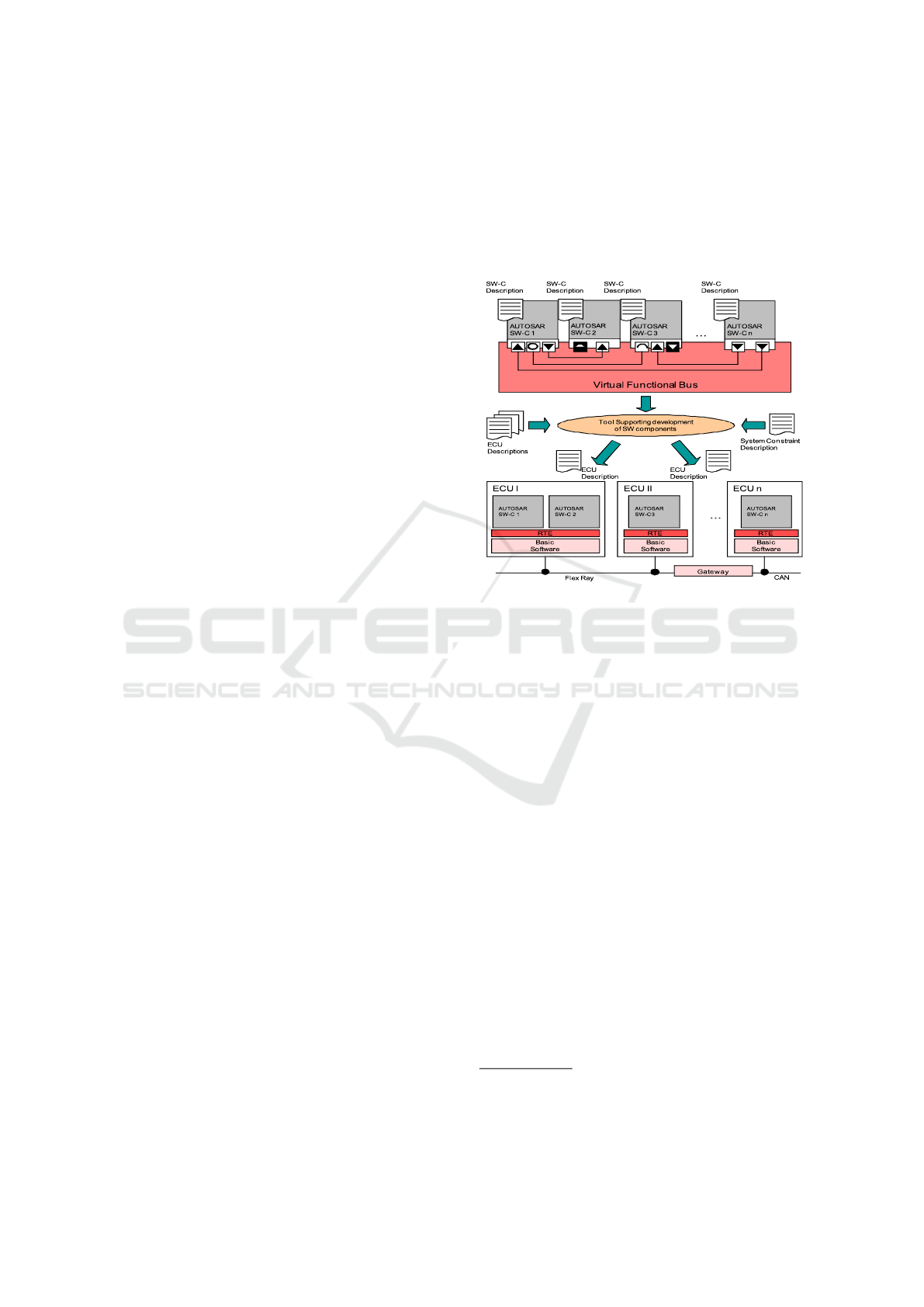
The various components of the AUTOSAR frame-
work are illustrated together with the mapping of soft-
ware components to ECUs, in the system configura-
tion step, in Fig. 1. The software components (seen
at the top of Fig. 1, e.g., SW-C1) are used to structure
the AUTOSAR model and group functionality into in-
dividual components. These components can be con-
nected together, oblivious of the hardware they will
be running on. This is handled by the Virtual Func-
tion Bus (VFB), which provides an abstraction layer
for the SWC to SWC communication. Components
distributed over different ECUs however, may use the
network bus for communication. This is determined
automatically by the Run-Time Environment (RTE),
which is a communication interface for the software
components.
The lower part of the Fig. 1 represents the map-
ping of ECUs to SW-Cs in the system configuration
step. Here, the ECUs 1, 2..n are seen communicat-
ing over a network bus (e.g. FlexRay, CAN). In each
ECU (e.g. ECU 1 in lower part of Fig. 1), the RTE
provides interfaces between SW-Cs (e.g. AUTOSAR
SW-C 1 and AUTOSAR SW-C 2 in ECU 1) and be-
tween SW-C and basic software (BSW). Further it
provides the BSW services (as API abstraction) to
SW-C.
The underlying software functions which imple-
ment the given requirements are contained inside the
SW-Cs. These are later on implemented manually by
the software developers. The RTE and Basic Soft-
ware (BSW) which are provided by third-party AU-
TOSAR software vendors are at the disposal of the
developer for communication and hardware abstrac-
tion. The inner functionality of the application and
sensor/actuator SWCs is defined in Internal Behavior
elements. They encapsulate Runnable Entities, which
correspond to atomic functions on the code level that
are implemented later in the development process.
Figure 1: Mapping of software components to ECUs in the
system configuration step.
In this paper, we deal with the system configuration
step and specification of timing properties in the SW-
Cs. The communication between the SWCs is mod-
eled by using communication ports.
2.2 Model-based Timing Specification
Alternatives for specifying timing behavior in the
UML domain have been introduced more than a
decade ago
6
. The Systems Modeling Language
(SysML)
7
, is often used as a standard, general pur-
pose modeling language for model-based systems en-
gineering. Modeling and Analysis of Real-Time
and Embedded Systems (MARTE)
8
is a standardized
UML profile, which extends UML and provides sup-
port for modeling the platform, software and hard-
ware aspects of an application (Iqbal et al., 2012),
(Peraldi and Sorel, 2008), (Anssi et al., 2011a). There
are several approaches in the direction of model-based
timing specification. But, modeling constraints using
AUTOSAR-TE and an automated extraction of tim-
ing parameters, synthesis of an analysis model and
analysis of the timing analysis model in a state-of-the-
6
http://www.omg.org/
7
http://www.omgsysml.org/
8
http://www.omg.org/omgmarte/
MODELSWARD 2020 - 8th International Conference on Model-Driven Engineering and Software Development
28

art timing analysis tool, such as SymTA/S, is miss-
ing. There are also several modeling alternatives in
non-UML domains such as SystemC (Bhasker, 2010),
Event-B
9
and Matlab/Simulink to name a few. Unlike
UML-based profiles, support for specification and
analysis of timing properties is very limited in Sys-
temC, Event-B and Matlab/Simulink. Related work
for the aforementioned alternatives can be found in
(Kirner et al., 2000), (Cervin et al., 2006), (Di Na-
tale et al., 2010), (Al-bayati et al., 2013). However,
in these studies, model-based timing analysis in auto-
motive embedded software systems is not discussed.
Further, several modeling languages, domain-specific
languages and a number of generic approaches have
emerged that include timing behavior. PTIDES (Zhao
et al., 2007), (Derler et al., 2011) and Giotto (Hen-
zinger et al., 2001) provide a good basis for defining
an approach to model timing requirements. However,
these are often used to analyze system behavior rather
than specification of timing properties (Alur, 1999),
(Amnell et al., 2001), (Kaynar et al., 2003).
2.2.1 AUTOSAR-timing Extensions
The AUTOSAR-timing Extensions (TE) metamodel
is separate from the AUTOSAR metamodel, in order
to leave the option whether to provide timing speci-
fications or not. They feature an event-based model
for the description of the software’s temporal behav-
ior and can be defined on top of a system architec-
ture. The AUTOSAR release with timing extensions
and own timing model, finds extensive usage in the
automotive industry. This is supported by studies in-
cluding (Hans et al., 2009), (Peraldi-Frati et al., 2012)
and (Ficek et al., 2012)
The TE metamodel (Fig. 2) provides five differ-
ent views for timing specification, depending on what
kind of timing behavior of the AUTOSAR model is
described (AUTOSAR, 2018). The five views are Vf-
bTiming, SwcTiming, SystemTiming, BswModuleTim-
ing and EcuTiming. In the experimental evaluation,
the SwcTiming view is employed, as in the system
configuration step and timing specification step the
SWCs are employed (cf. section 2.1.1). SwcTiming
view describes the internal behavior timing of soft-
ware components. Further explanation of AUTOSAR
methodology and AUTOSAR-TE are not provided
here because of space limitations (interested readers
are referred to (AUTOSAR, 2018)).
9
http://www.event-b.org/index.html
2.2.2 Model-based Timing Analysis
The specified timing behavior can be analyzed us-
ing dedicated timing analysis tools. There are several
open source tools such as Cheddar (Singhoff et al.,
2004) and MAST (Harbour et al., 2001). Some pop-
ular proprietary timing analysis tools include chron-
SIM (INCHRON, 2019), SymTA/S (Henia et al.,
2005) and Timing Architect
10
. These tools are in-
dependent of the modeling languages used. There-
fore, they require the timing specifications to be in a
particular format, although some provide import func-
tions for common modeling languages. But, there is
no tool support for automated synthesis and export
of AUTOSAR-based timing analysis model (from
AUTOSAR-based application design model in UML
tools) to these timing analysis tools. AUTOSAR
TE were used for a model-based timing analysis in
works such as (Anssi et al., 2011b), (Klobedanz et al.,
2010), (Kim et al., 2016) and (Scheickl et al., 2012).
Some do not have a systematic model-based approach
in timing analysis of AUTOSAR systems. Whereas
a few others do not concentrate on synthesis of a
AUTOSAR-based timing analysis model. It is imper-
ative to note that the design errors realised from such
late timing analysis would be costly to fix at a later
development stage.
A recently developed work on timing and schedul-
ing employing a timing metamodel is available in
the AMALTHEA platform
11
. This platform allows
users to distribute data and tasks to the target hard-
ware platforms, with the focus on optimization of tim-
ing and scheduling. However, timing modeling in
AMALTHEA has to be done at the EMF level and
not the UML model level. Further, there is no tool
support in AMALTHEA to synthesize an AUTOSAR-
based timing analysis model from the ARXML files
of the timing annotated design model (esp. from
UML tools).
2.3 Research Gaps and Challenges
Addressed
On examining the related work, it can be stated that
validation of timing properties early in AUTOSAR-
based automotive embedded software development in
UML tools, especially in specialized timing analy-
sis tools is beneficial. Nevertheless an approach to-
wards realising this is missing. The main input re-
quired for such timing analysis in specialized timing
analysis tools (e.g. in SymTA/S, chronSIM) is the
10
https://www.timing-architects.com/
11
https://www.eclipse.org/app4mc/
Early Synthesis of Timing Models in AUTOSAR-based Automotive Embedded Software Systems
29
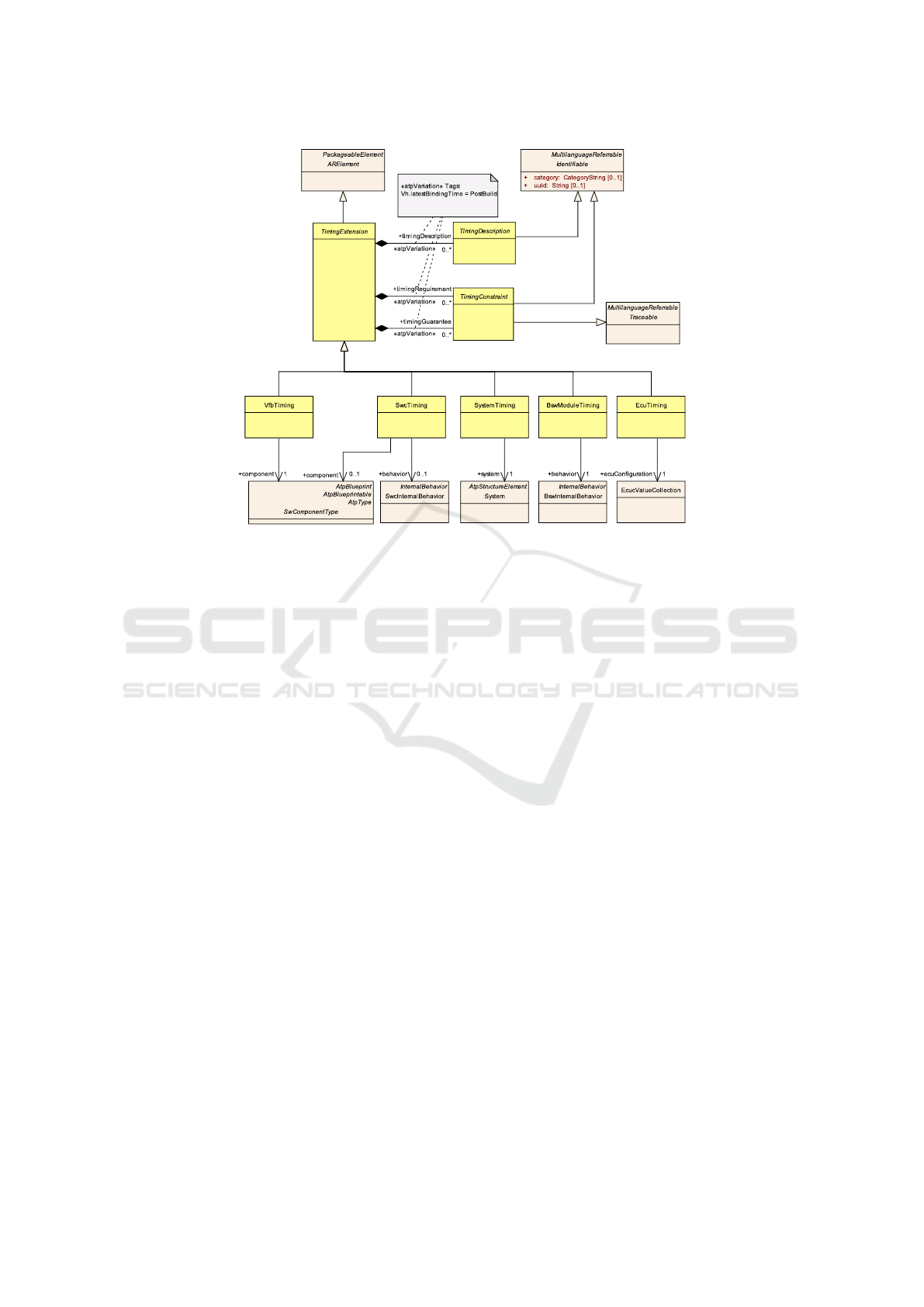
Figure 2: Overview of AUTOSAR Timing Extensions (TE) metamodel (AUTOSAR, 2018).
AUTOSAR-timing model corresponding to the anno-
tated AUTOSAR-based design model developed in
UML tool. Thus, synthesis of a timing analysis model
from AUTOSAR-based design model in UML tools
forms an important step. With the help of such a tim-
ing analysis model a systematic and extensive tim-
ing validation can be carried out in specialized tim-
ing analysis tools, in early development stages. Ad-
dressing the gaps identified above and in line with the
novelties outlined in section 1, in the remainder of
this paper, the steps involved in synthesis of a tim-
ing analysis model and an experimental evaluation are
presented in section 3 and 4 respectively.
3 SYNTHESIS OF TIMING
MODEL
The proposed approach for the synthesis of a timing
analysis model is outlined in section 3.1. The generic
timing metamodel and its mapping to the AUTOSAR
metamodel elements are discussed in section 3.2 and
3.3 respectively. The model transformations are de-
tailed in section 3.4.
3.1 Steps Involved in the Synthesis of
Timing Analysis Model
The proposed approach for automated synthesis of an
AUTOSAR timing analysis model is shown in Fig. 3
and comprises of the following steps.
(a) In the first step, it is considered that an initial
AUTOSAR-based design model of the automo-
tive embedded software application under con-
sideration is already modeled in the UML tool
(e.g. Rhapsody developer). Note that step-(a) in
Fig. 3 is applied in an early stage of develop-
ment process. Step-(a) involves the specification
of the timing requirements in the design model
using AUTOSAR-TE to obtain an annotated AU-
TOSAR design model.
(b) In line with the main scope of this paper, an
AUTOSAR-based timing analysis model needs to
be synthesised based on the inputs from step-(a)
in Fig. 3. For this purpose, given the timing
annotated design model as input, model transfor-
mations are implemented for extracting the tim-
ing properties. This results in the synthesis of
the AUTOSAR-timing analysis model (conform-
ing to a generic metamodel, cf. section 3.2). Thus,
the output of step-(b) in Fig. 3 is the synthesized
AUTOSAR timing model, which can be used for
timing validation in timing analysis tools such as
SymTA/S and Timing Architect.
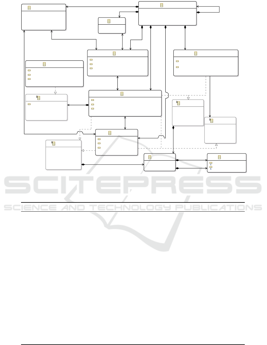
3.2 Intermediate Generic Timing
Metamodel
As mentioned earlier, a generic timing metamodel
has been developed using the EMF and introduced in
MODELSWARD 2020 - 8th International Conference on Model-Driven Engineering and Software Development
30
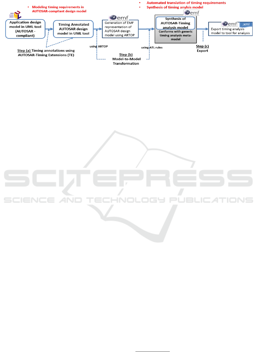
Figure 3: Steps involved in synthesis of timing analysis model incorporated in AUTOSAR development process.
(Iyenghar et al., 2016). This metamodel comprises
of a basic set of timing properties needed for per-
forming a timing analysis. This can be termed as a
generic metamodel, as it closely adheres with timing
models used in several timing validation tools (e.g.
SymTA/S). This intermediate timing metamodel also
bears similarity to the AUTOSAR metamodel in re-
spect to the software and hardware architecture ele-
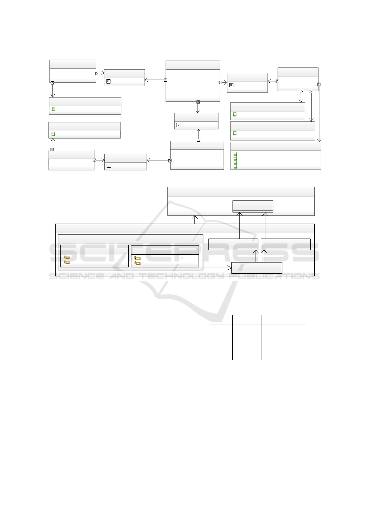
ments. The main elements of the metamodel can be
seen in Fig. 4. It consists of elements such as Pack-
ages, containing the different model elements such
as Runnables, SoftwareComponents, Tasks, Cores,
ECUs and ExecutionPaths.
A Runnable represents an operation, or a function.
It is contained in a SoftwareComponent and executed
by a Task. These tasks have specific activation mod-
els, e.g. a periodic activation, which triggers the task
with a certain period. They can also have priorities,
which make it possible to preempt a task (of a pre-
emptible taskType) when a different task with a higher
priority is to be executed. A task can execute multi-
ple runnables in a row, whose order attribute states,
which runnable comes first. Additionally, runnables
are only executed at a multiple of the repetitionFac-
tor and they have a baseCycle attribute, which spec-
ifies, at which task execution they are going to be
executed the first time. Every task is assigned to a
Core, which is in turn assigned to an ECU. The Ex-
ecutionPaths in the model can be used to represent
an end-to-end functionality. They aggregate either a
set of runnables or a set of tasks as ordered path ele-
ments. Timing properties such as executionTimes can
be added to tasks or runnables and responseTimes can
be added to tasks or execution paths. They are spec-
ified with a TimeBoundary, which contains an upper
and a lower time bound.
3.3 Mapping Among Metamodels
In this section, the relevant metamodel elements from
the intermediate timing metamodel (cf. section 3.2,
Fig. 4) are mapped to their counterparts in the AU-
TOSAR metamodel (AUTOSAR, 2018). The AU-
TOSAR Tool Platform
12
provides an EMF model,
which contains the element names as per specifica-
tion. An evaluation version of this AUTOSAR EMF
model is used in this paper for mapping the timing
metamodel elements to the AUTOSAR metamodel el-
ements. It is also used as an input metamodel for the
automated model transformations (cf. section 3.4).
A summary of relevant mappings of elements is
shown in Table 1. Please note that most of the el-
ements described in Table 1 are show in Fig. 4.
However, some elements such as Model, ICATObject,
Clock and System are not shown in Fig. 4 because of
space constraints. In the following, these mappings
are described in more detail.
1. The top-most element of every AUTOSAR model
is the AUTOSAR element. It denotes the AU-
TOSAR revision and links to the corresponding
XML schema definition. This element is mapped
to the Model element, as it represents a dedicated
model.
2. All following AUTOSAR elements inherit from
Identifiable, which provides name, description
and id parameters for the ICATObject element, on
which the timing metamodel elements are based
upon.
3. The ARPackage element gets mapped to the Pack-
age timing element, as it structures the different
AUTOSAR elements in packages and subpack-
ages.
4. The mapping of software components is straight-
forward, because these elements exist similarly as
central modeling elements in the AUTOSAR stan-
dard. Every AtomicSwComponentType of the AU-
TOSAR application model is mapped to a Soft-
wareComponent in the timing metamodel. This
includes SensorActuatorSwComponentTypes and
ApplicationSwComponentTypes, as they inherit
from the atomic software component type.
12
https://www.artop.org/
Early Synthesis of Timing Models in AUTOSAR-based Automotive Embedded Software Systems
31
Package
Core
scheduler : EString
minTotalLoad : EDouble =
0
maxTotalLoad : EDouble =
1
ECU
ExecutionPath
semantic : ExecutionPathSemantic =
ReactionSemantic
hasSampleDelay : EBoolean = false
Runnable
repetitionFactor : EInt = 1
baseCycle : EInt = 0
order : EInt = 0
Task
useRunnables : UseRunnables = IfExist
taskType : TaskType = Cooperative
priority : EInt =
0
IPathElement
IResponseTim
e
IExecutionTime
TimeBoundary
TimeValue
value : EDouble = 0.0
unit : TimeUnit = ms
SoftwareComponent
IEventModel
timeUnit : TimeUnit =
ms
SimplePeriodic
period : EDouble = 0.
0
jitter : EDouble = 0.
0
[0..*] subPackages
[0..*] runnables
[0..*] cores
[0..*] tasks
[0..*] ecus
[0..*] executionPaths
[0..*] runnables
[0..1] parentTask
[0..1] parentCore
[0..*] tasks
[0..*] cores
[0..1] parentECU
[0..*] pathElements
[0..1] responseTime
[0..1] coreExecutionTime
[0..1] lowerBound
[0..1] upperBound
[0..*] softwareComponents
[0..*] runnables
[0..1] parentSWComponent
[0..1] parentCore
[0..*] softwareComponents
[0..1] activation
minimumDistance : EDouble = 0.0
Figure 4: Excerpt of the timing metamodel (Iyenghar et al., 2016).
Table 1: Mapping of elements in proposed generic metamodel (in Fig. 4) to AUTOSAR elements.
Nr Timing element in Fig. 4 AUTOSAR element Description
1 Model AUTOSAR Top-level model element
2 ICATObject Identifiable Identifiable element
3 Package ARPackage Structuring element
4 SoftwareComponent AtomicSwComponentType Encapsulates functionality
5 Runnable RunnableEntity Executable operation
period Period of TimingEvent Period of operation
coreExecutionTime LatencyTimingConstraint Execution time of runnable
order RtePositionInTask Execution order of runnable
baseCycle RteActivationOffset First runnable execution
repetitionFactor runnable period / task period How often it is executed
6 ECU EcuInstance Electronic control unit
7 Core HwElement Processing core
8 Clock OsCounter Synchronization element
period OsSecondsPerTick Seconds per clock tick
9 System System Network of ECUs
10 Task OsTask Schedulable unit
priority OsTaskPriority Fixed priority of task
taskType OsTaskSchedule Preemptability of task
synchronizationMechanism OsAlarmCounterRef Reference clock
synchronizationOffset OsAlarmAlarmTime Offset for the reference clock
activation OsAlarmCycleTime Periodic task activation
11 ExecutionPath TimingDescriptionEventChain End-to-end path
5. The Runnable timing elements exist in AU-
TOSAR inside the InternalBehavior of an Atom-
icSwComponentType as RunnableEntities. They
represent the executable operations of the soft-
MODELSWARD 2020 - 8th International Conference on Model-Driven Engineering and Software Development
32

ware components.
6. The ECU elements can be mapped to the AU-
TOSAR EcuInstance. This is used for linking the
software components, and therefore runnables, to
their dedicated ECUs, on which they are later on
implemented and executed.
7. The Core elements are mapped to HwElements in
the AUTOSAR model. They need to be linked to
a HwCategory of the type ProcessingCore. Each
core belongs to an ECU and is linked to it in the
system mapping.
8. The Clock element is mapped to an OsCounter el-
ement in the AUTOSAR operating system config-
uration. It provides an OsSecondsPerTick param-
eter, which can be translated to a period by taking
the inverse value.
9. The System element in timing metamodel corre-
sponds to a System element AUTOSAR model.
Overall, they represent a top-level element corre-
sponding to a network of ECUs.
10. Task elements are created in the AUTOSAR Os
configuration as OsTasks. A task is defined as a
schedulable unit in timing analysis.
11. The end-to-end ExecutionPaths in the timing
metamodel can be represented in the AUTOSAR
model as TimingDescriptionEventChains. These
event chains group a set of events belonging to the
activation and termination of runnable entities.
3.4 Model Transformations
After step (a) in Fig. 3 (cf. section 3.1), a timing
annotated AUTOSAR design model is now available
(also in ARXML format (AUTOSAR, 2018)). This is
provided as input for step (b) in Fig. 3.
Note that while employing Model-to-Model
(M2M) transformations, both source and target mod-
els must conform with their respective metamodels.
Here the source model is the annotated AUTOSAR
design model obtained from the system description
specification in the Rhapsody UML tool in ARXML
format. This conforms with the AUTOSAR meta-
model (AUTOSAR, 2018). The target metamodel is
the timing metamodel introduced in section 3.2. Dur-
ing the M2M transformations the timing properties
are extracted from the annotated AUTOSAR design
model (developed in chosen UML tool) and a corre-
sponding instance of the timing analysis target meta-
model is synthesized. Note that here both the meta-
models are available in EMF format. The synthesized
model is also available in EMF and XML formats,
may now be used for timing validation in timing anal-
ysis tools such as SymTA/S.
In this work, the ATLAS transformation language
(ATL)
13
is used for implementing the M2M transfor-
mations. ATL is a widely used M2M transforma-
tion language, readily available as plug-in for Eclipse
development environment. Thus using ATL, a set
of rules can be written to transform the AUTOSAR-
based design model to an instance of the intermediate
timing meta model, based on the mappings listed in
Table 1.
In other words, declarative rules map elements
from the input timing annotated AUTOSAR-design
model to the intermediate timing metamodel and
create a corresponding instance of the AUTOSAR-
timing analysis model. In these rules, the elements
can either be altered (e.g., attribute changes) or new
elements from a different metamodel can be created
for each mapped element. The latter is called an out-
place transformation, because it creates a new output
model, which may conform to any metamodel. In or-
der to transform an AUTOSAR-based design model
annotated with timing attributes, to an instance of the
intermediate timing metamodel (cf. Fig. 4), such out-
place transformations are proposed.
The outline of the transformation can be seen in
Fig. 5. At the center is the autosarToTiming.atl file,
which contains the matching-rules, mapping from the
AUTOSAR to timing metamodel according to sec-
tion 3.3. This file references both metamodels (MM),
namely AUTOSAR MM and Timing MM, which are
available as Ecore
14
models. Together with the an-
notated AUTOSAR-based design model, available as
ARXML file, the mapping rules are used as input by
the ATL Execution Engine to produce a correspond-
ing Timing model as output.
Listing 1: Examples of ATL rules.
1 abstract rule Id e n t i f ia b l e 2 I C A T O b j e c t {
2 from
3 in p u t : AR ! I d e n t if i a b l e
4 to
5 out p u t : T i m i ng ! I C A T O b j e c t (
6 na me < - input . s hort N ame ,
7 descr i p t i o n <- in p u t . d esc )}
8 rule A t o m i c S W C 2 S W C o m p o n e n t extends
9 I d e n ti f i a b le 2 I C A T O b j e c t {
10 from
11 inp u t : AR ! At o mi c S w C o m p o n e n tT y p e
12 to
13 outpu t : T i m i n g ! So f t w a r e C o m p o n e n t (
14 runnables < - i nput . i n t e r n a l B e h a v i o r s
15 -> co l l ect ( ib | ib . r u n n a b l e s )
16 -> f l a t t e n () )}
13
http://www.eclipse.org/atl/
14
https://www.eclipse.org/ecoretools/doc/
Early Synthesis of Timing Models in AUTOSAR-based Automotive Embedded Software Systems
33
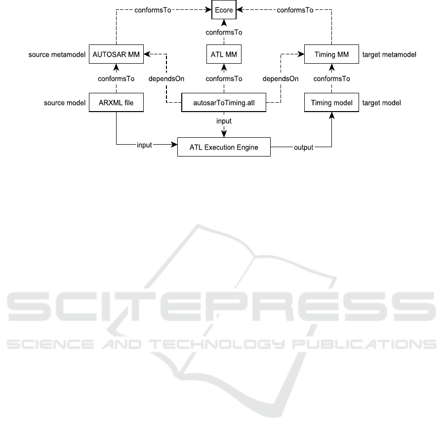
Figure 5: AUTOSAR to timing model transformation pattern.
The rules consist of a source pattern in the from sec-
tion and a target pattern in the to section. The source
pattern specifies the type of the source model ele-
ment to be matched and the target pattern contains
the output model element that will be created by the
transformation for each source element. The first rule
Identifiable2ICATObject (line:1-7 in listing 1)
maps the Identifiable element to the ICATObject
element and assigns the name and description at-
tributes according to the shortName and desc tags
from the AUTOSAR model element. All relevant AU-
TOSAR elements from Table 1, except the top-most
AUTOSAR element, inherit from the Identifiable el-
ement. Thus, they all feature a name and a descrip-
tion parameter. Hence, the Identifiable2ICAT-
Object rule can be reused for all other rules in the
ATL file as a parent rule. Therefore, it is distinguished
as an abstract rule. This means, it is not going to
be matched directly on Identifiable elements, but
rather is the target pattern inherited by the inheriting
rules.
For example, the AtomicSWC2SWComponent rule
(line: 8-16 in listing 1) extends the parent rule
Identifiable2ICATObject and thus, its target pat-
tern is inherited. This means that, the target ele-
ment SoftwareComponent automatically receives the
name and description attributes. Additionally, it re-
ceives the runnables attribute specified in the new
target pattern, to link to the software component’s
runnables. To collect the runnable elements, the in-
ternal behavior elements of the software component
are accessed, because they store the runnable enti-
ties in the AUTOSAR model. The collect oper-
ation iterates through all internal behavior elements
(ib) and returns the list of runnables for each. As this
statement returns a two-dimensional list, the flatten
operation ensures that a list directly containing the
runnables is returned and assigned to the runnables
attribute.
Similar to the above rules, for the remaining el-
ements in table 1, a total of fifteen rules are imple-
mented in the prototype. Please note that, the pro-
posed steps (a), (b) in Fig. 3 are independent of the
timing analysis tool. With the timing information
gathered in the AUTOSAR modeling phase and ex-
tracted by the model transformations according to the
mappings in 3.3, a timing analysis model is synthe-
sized. This model may now be used for various types
of timing validation in timing analysis tools.
4 AUTONOMOUS EMERGENCY
BRAKING SYSTEM EXAMPLE
The main purpose of Autonomous Emergency Brak-
ing Systems (AEBSs) is to warn the driver in case of
an imminent frontal collision. This happens through
visual and acoustic warning signals as a first step,
followed by a tactile warning as the next level.
The AEBS in cars use the Time-To-Collision (TTC)
value (van der Horst and Hogema, 1993)(Kusano and
Gabler, 2011) to estimate the danger of the situation.
It is defined as the time left until a collision hap-
pens, if every object continues to move at the same
speed. To calculate TTC, AEBS needs data such as
the distance to frontal objects (e.g. from rador sen-
sors) and wheel speed sensor input at certain speed
ranges. Please note that, though an extensive use case
has been implemented for experimental evaluation,
only a very brief subset of details are presented in this
section due to space limitations.
MODELSWARD 2020 - 8th International Conference on Model-Driven Engineering and Software Development
34

4.1 AUTOSAR Design Model
The AUTOSAR system description of the AEBS is
modeled using the IBM Rational Rhapsody Devel-
oper modeling tool (IBM Software, 2019). Rhapsody
is among the most popular UML modeling tool with
AUTOSAR support used in the automotive industry,
hence it is used in this paper.
The first step in implementing the AUTOSAR de-
sign model is to define the software components, of
which the system is composed of as shown in Fig. 6.
• The sensor filter modules on the left-hand side
are modeled as SensorActuatorSwComponent-
Types. They have client ports (speedSensorPort,
radarSensorPort) to be able to connect to the cor-
responding sensors. These ports are typed by
ClientServerInterfaces that provide an operation
for retrieving the sensor value. This is illustrated
by the association between the ports and the in-
terfaces, which is stereotyped as a portType. The
rest of the modules are modeled as Application-
SwComponentTypes, as they do not directly rep-
resent a sensor or an actuator.
• The communication between the sensor filters
and the CollisionDetection and ObstacleLoca-
tion components happens through sender/receiver
ports. The filtered dataElements get sent to the
processing components. Equally, the Obstacle-
Location sends a list of obstacles (comprising
of distance and relative speed) to the Collision-
Detection. The communication between Colli-
sionDetection and DriverWarning is also typed
as sender/receiver and the corresponding dataEle-
ment is the TTC value.
• In the end, the DriverWarning component is con-
nected by client ports (ledPort, speakerPort and
brakePort) to the three actuators. The correspond-
ing interfaces provide the necessary operations for
the different levels of driver warning, e.g., setting
the warning LED light status (setLight), playing a
warning sound (playWarningSound) or perform-
ing an emergency brake (emergencyBrake).
4.2 Timing Specification
The timing constraints of the AEBS are added to the
model in Fig. 6 with the help of AUTOSAR-TE in the
UML tool Rhapsody.
Fig. 7 shows a latency constraint for the check-
TTC runnable entity of the DriverWarning software
component (seen at top-right of Fig. 6). An Swc-
Timing is created for each software component in the
AEBS, which link to the component’s internal be-
havior with the l behavior association. Inside these
elements, two TDEventSwcInternalBehaviors are de-
fined for each runnable entity (in this case, checkTTC
of IBDriverWarning). The first event highlights the
activation of the runnable, while the second highlights
the termination. This is defined by setting the tag td-
EventSwcInternalBehaviorType of the timing event to
either runnableEntityActivated or runnableEntityTer-
minated. Both these events are now used to form
a TimingDescriptionEventChain, in which the event
chain stimulus is the runnable activation and the event
chain response is the runnable termination.
Finally, the core execution time of the runnable
checkTTC is specified by the checkTTCLatency-
Constraint that links to its event chain with l scope.
The role timingGuarantee stereotype declares that
this constraint is the expected execution time instead
of a requirement (role timingRequirement). The re-
lated timing information can be given as maximum
and minimum execution time and is specified by
ASAM CSE codes (Scheid, 2015). The cseCode
specifies the time base (e.g., 2 = 100µs, 3 = 1ms and
4 = 10ms) and the cseCodeFactor determines an inte-
ger scaling factor. Thus, in this case, the execution
time of the checkTTC runnable entity lies between
3ms and 5ms.
4.3 Model Transformations
In the above steps, the AUTOSAR-based de-
sign model and its corresponding timing annotated
AUTOSAR-based design model are created in the
UML modeling tool Rhapsody (cf. step(a) in Fig. 3).
This model is exported from the UML tool in the in-
terchangeable AUTOSAR ARXML format for M2M
transformations (cf. step (b) in Fig. 3). The trans-
formations are invoked in the experimental evaluation
directly from the Eclipse development environment.
The synthesized AUTOSAR-timing analysis
model of the AEBS use case is shown in Fig. 8.
The necessary elements for a timing analysis were
extracted from the AUTOSAR design model anno-
tated with timing properties (cf. Fig. 6, 7) according
to the mapping in Table 1. As seen in Fig. 8, the
AEBS model is structured by different Packages and
the System element contains the complete software
and hardware elements in a hierarchy. For example,
the runnable timeToCollision with its corresponding
execution time can be seen, allocated to the System-
Task, which is in turn allocated to Core1 of the ECU.
Please note that the results from timing validation of
the synthesized timing model in specialized timing
analysis tools such as SymTA/S, are not presented in
this paper due to space limitations.
A quantitative performance analysis of the pro-
Early Synthesis of Timing Models in AUTOSAR-based Automotive Embedded Software Systems
35
CollisionDetection
«ApplicationSwComponentType»
obsPort:IfObstacles
speedPort:IfSpeed
TTCPort:IfTTC
obsPort:IfObstacles
speedPort:IfSpeed
TTCPort:IfTTC
ObstacleLocation
«ApplicationSwComponentType»
distPort:IfDistance
obsPort:IfObstacles
distPort:IfDistance
obsPort:IfObstacles
DriverWarning
«ApplicationSwComponentType»
brakePort:IfBrake
speakerPort:IfSpeaker
ledPort:IfLED
TTCPort:IfTTC
brakePort:IfBrake
speakerPort:IfSpeaker
ledPort:IfLED
TTCPort:IfTTC
SpeedFilter
«SensorActuatorSwComponentType»
speedSensorPort:IfSpeedSensor
speedPort:IfSpeed
speedSensorPort:IfSpeedSensor
speedPort:IfSpeed
DistanceFilter
«SensorActuatorSwComponentType»
radarSensorPort:IfRadarSensor
distPort:IfDistance
radarSensorPort:IfRadarSensor
distPort:IfDistance
IfTTC
«SenderReceiverInterface»
«dataElement» ttc:int
IfLED
«ClientServerInterface»
«ClientServerOperation» setLight(on:Boolean):void
IfSpeaker
«ClientServerInterface»
«ClientServerOperation» playWarningSound():void
IfBrake
«ClientServerInterface»
«ClientServerOperation» emergencyBrake():void
«ClientServerOperation» prepareBrake():void
«ClientServerOperation» releaseBrake():void
«ClientServerOperation» warningBrake():void
IfSpeedSensor
«ClientServerInterface»
«ClientServerOperation» getSensorValue():int
IfRadarSensor
«ClientServerInterface»
«ClientServerOperation» getSensorValue():int
IfSpeed
«SenderReceiverInterface»
«dataElement» speed:int
IfDistance
«SenderReceiverInterface»
«dataElement» distance:int
IfObstacles
«SenderReceiverInterface»
«dataElement» obstacles:list
Figure 6: AEBS software components as seen in the software component diagram modeled in Rhapsody.
DriverWarningTiming
«SwcTiming»
checkTTCActivated
«TDEventSwcInternalBehavior»
checkTTCTerminated
«TDEventSwcInternalBehavior»
checkTTCLatencyConstraint
«LatencyTimingConstraint,role_timingGuarantee»
minLatency
«minimum»
cseCode:CseCodeType=3
cseCodeFactor:RhpInteger=3
maxLatency
«maximum»
cseCode:CseCodeType=3
cseCodeFactor:RhpInteger=5
checkTTCEventChain
«TimingDescriptionEventChain»
«l_response»
«l_stimulus»
«l_scope»
Application::SoftwareComponents::DriverWarning::IBDriverWarning
1
«SwcInternalBehavior»
checkTTC
1
«RunnableEntity»
«l_runnable» «l_runnable»
«l_behavior»
Figure 7: Timing attributes for the checkTTC runnable entity.
totype was carried out by invoking the transforma-
tions for the AEBS use case with varying number of
SWCs in the AUTOSAR-UML design model. This is
because, the number of software components (apart
from tasks) may be considered as a primary factor
for computing complexities involved in schedulabil-
ity analysis of systems.
For varying input size (i.e., SWCs in annotated
design model), time and memory requirement of the
ATL module to synthesize the respective instance of
the AUTOSAR-timing analysis model is determined
(cf. Table 2). The experiments were carried out on a
standard X-86 based host with Windows-XP OS. The
results indicate that the ATL transformations termi-
nate once the generation of the timing analysis model
is completed.
The generation time and memory requirement
is bounded for varying input sizes. This demon-
strates the applicability and suitability of the steps
involved in the proposed approach for early, auto-
matic synthesis of AUTOSAR-timing analysis model
from AUTOSAR-based design models developed in
Table 2: Set of inputs, time & memory requirement on a
standard X-86 based host (with Windows-XP OS), for au-
tosarToTiming ATL module.
SWCs Time (s) Memory(MB)
4 10.3 2.1
10 23.3 3.3
18 40.2 5.3
23 46.34 8.7
UML tools. Please note that a detailed analysis of
the transformations such as their computational com-
plexity are not provided in this paper, due to space
limitations.
5 CONCLUSION
In this paper, an approach towards early synthesis of
AUTOSAR-based timing models from timing anno-
MODELSWARD 2020 - 8th International Conference on Model-Driven Engineering and Software Development
36
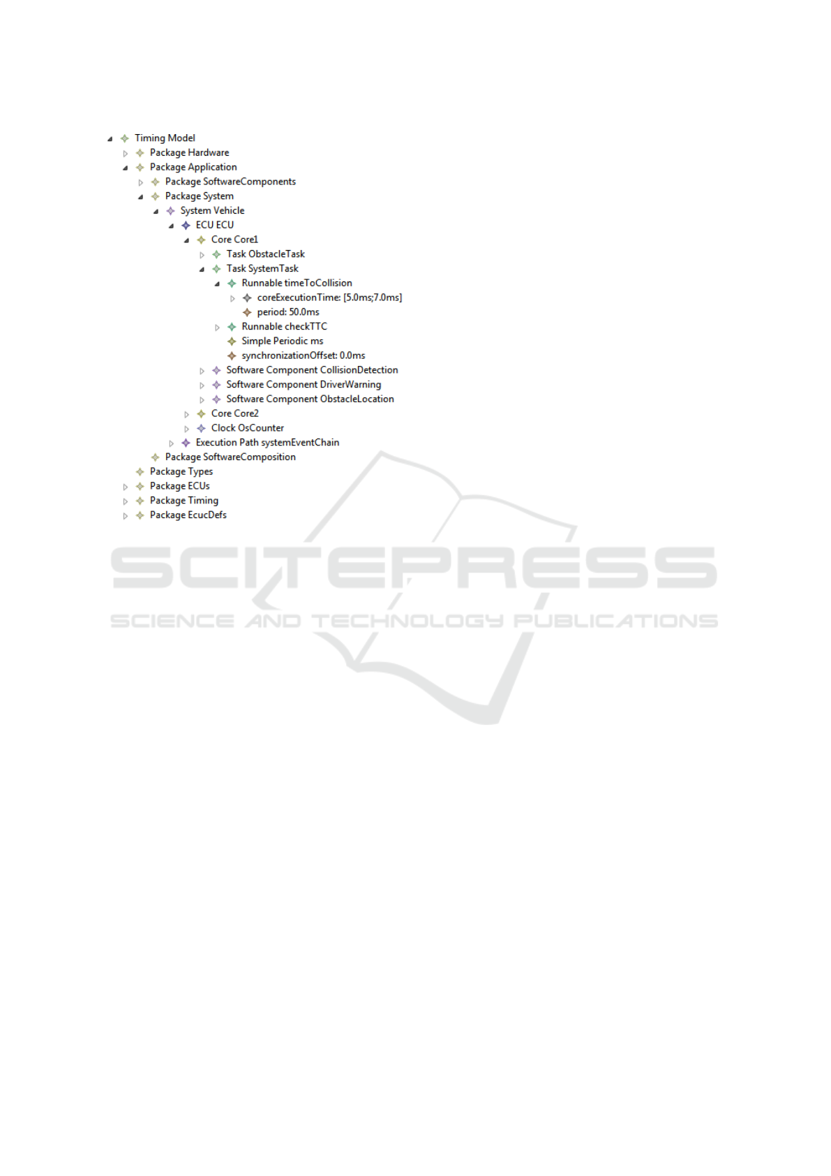
Figure 8: Synthesized timing model of AEBS use case.
tated AUTOSAR-based design models, developed in
state-of-the-art UML tools, is presented. ATL trans-
formations are employed to extract timing properties
from the timing annotated AUTOSAR-based design
model to generate a timing analysis model. The tim-
ing analysis model was synthesized in the early stages
of AUTOSAR-development process. Timing analy-
sis of this model in specialized timing analysis tools
(e.g. SymTA/S, chronSIM and Timing Architect)
would provide an early estimated timing behavior of
the system. At such an early development phase this
enables design changes without much consequences.
An AEBS practical use case was employed for exper-
imental evaluation. Extending this approach to dis-
tributed systems is an item for future work.
ACKNOWLEDGEMENTS
This work is supported by a grant (id:
KF2312004KM4) from BMWi-ZIM co-operation,
Germany and carried out in cooperation with Willert
Software Tools GmbH and SymtaVision GmbH.
REFERENCES
Al-bayati, Z., Zeng, H., Di Natale, M., and Gu, Z. (2013).
Multitask implementation of synchronous reactive
models with earliest deadline first scheduling. In In-
dustrial Embedded Systems (SIES), 2013 8th IEEE In-
ternational Symposium on, pages 168–177.
Alur, R. (1999). Proceedings of Computer Aided Verifica-
tion: 11th International Conference, CAV’99, chapter
Timed Automata, pages 8–22. Springer.
Amnell, T., Behrmann, G., Bengtsson, J., et al. (2001).
Modeling and Verification of Parallel Processes:
MOVEP 2000, Revised Tutorial Lectures, chapter
UPPAAL - Now, Next, and Future, pages 99–124.
Springer.
Anssi, S., G
´
erard, S., Kuntz, S., and Terrier, F. (2011a). Au-
tosar vs. marte for enabling timing analysis of automo-
tive applications. In International SDL Forum, pages
262–275. Springer.
Anssi, S., Tucci-Piergiovanni, S., Kuntz, S., G
´
erard, S., and
Terrier, F. (2011b). Enabling scheduling analysis for
autosar systems. In IEEE ISORC 2011, pages 152–
159. IEEE.
AUTOSAR (2018). Release 4.4.0: Methodology and
templates. https://www.autosar.org/standards/classic-
platform/classic-platform-440/. Accessed Nov 2019.
Bhasker, J. (2010). A SystemC Primer. Star Galaxy.
Bosch GmbH, editor (2014). Bosch Automotive Electrics
and Automotive Electronics. Springer.
Bucaioni, A., Cicchetti, A., Ciccozzi, F., Mubeen, S., and
Sj
¨
odin, M. (2017). A metamodel for the rubus com-
ponent model: Extensions for timing and model trans-
formation from east-adl. IEEE Access, 5:9005–9020.
Cervin, A., Arzen, K. E., Henriksson, D., Lluesma, M., Bal-
bastre, P., Ripoll, I., and Crespo, A. (2006). Control
loop timing analysis using truetime and jitterbug. In
IEEE International Conference Computer Aided Con-
trol System Design.
Derler, P., Eidson, J., Lee, E. A., Matic, S., and Zimmer, M.
(2011). Model-based development of deterministic,
event-driven, real-time distributed systems. In Work-
shop on Model-Based Design with a Focus on Extra-
Functional Properties.
Di Natale, M., Guo, L., Zeng, H., and Sangiovanni-
Vincentelli, A. (2010). Synthesis of multitask imple-
mentations of simulink models with minimum delays.
IEEE Transactions on Industrial Informatics, 6/4.
Ficek, C., Feiertag, N., Richter, K., and Jersak, M. (2012).
Applying the AUTOSAR timing protection to build
safe and efficient ISO 26262 mixed-criticality sys-
tems. Proceedings of ERTS.
Franco, F. R. and et. al (2016). Workflow and toolchain for
developing the automotive software according autosar
standard at a virtual-ecu. In 2016 IEEE 25th Inter-
national Symposium on Industrial Electronics (ISIE),
pages 869–875.
Hans, B., Rolf, J., and Henrik, L. (2009). Annotation with
Timing Constraints in the Context of EAST-ADL2
and AUTOSAR-the Timing Augmented Description
Language. In STANDRTS’09.
Early Synthesis of Timing Models in AUTOSAR-based Automotive Embedded Software Systems
37

Harbour, M. G., Garc
´
ıa, J. G., Guti
´
errez, J. P., and Moyano,
J. D. (2001). Mast: Modeling and analysis suite for
real time applications. In Real-Time Systems, 13th Eu-
romicro Conference on, 2001., pages 125–134. IEEE.
Henia, R., Hamann, A., Jersak, M., Racu, R., Richter, K.,
and Ernst, R. (2005). System level performance anal-
ysis – the symta/s approach. IEE Proceedings – Com-
puters and Digital Techniques, 152(2):148–166.
Henzinger, T. A., Horowitz, B., and Kirsch, C. M. (2001).
Giotto: A time-triggered language for embedded pro-
gramming. In Proceedings of the 1st International
Workshop on Embedded Software, EMSOFT ’01.
IBM Software (2019). Ibm rational rhapsody developer.
https://www.ibm.com/software/products/en/ratirhap.
Accessed Nov 2019.
INCHRON (2019). chronSIM.
https://www.inchron.com/tool-suite/chronsim.html.
Nov 2019.
Iqbal, M. Z., Ali, S., Yue, T., and Briand, L. (2012). Ex-
periences of Applying UML/MARTE on Three Indus-
trial Projects. In Proceedings of the 15th International
Conference MODELS’12.
Iyenghar, P., Noyer, A., Engelhardt, J., Pulverm
¨
uller, E.,
and Westerkamp, C. (2016). End-to-end path delay
estimation in embedded software involving heteroge-
neous models. In 11th IEEE Symposium on Industrial
Embedded Systems, SIES, 2016, pages 183–188.
Iyenghar, P. and Pulvermueller, E. (2018). A model-driven
workflow for energy-aware scheduling analysis of iot-
enabled use cases. IEEE Internet of Things Journal,
5(6):4914–4925.
Jianqiang, W., Shengbo, L., Xiaoyu, H., and Keqiang,
L. (2010). Driving simulation platform applied to
develop driving assistance systems. IET Intelligent
Transport Systems, 4(2):121–127.
Kaynar, D. K., Lynch, N., Segala, R., and Vaandrager, F.
(2003). Timed I/O Automata: A Mathematical Frame-
work for Modeling and Analyzing Real-Time Sys-
tems. In Proceedings of the 24th IEEE RTSS.
Kim, J. H., Kang, I., Kang, S., and Boudjadar, A.
(2016). A process algebraic approach to resource-
parameterized timing analysis of automotive software
architectures. IEEE Transactions on Industrial Infor-
matics, 12(2):655–671.
Kirner, R., Lang, R., Puschner, P., and Temple, C. (2000).
Integrating WCET Analysis into a Matlab/Simulink
Simulation Model. In Proceedings of 16th IFAC Work-
shop on Distributed Computer Control Systems 2000.
Klobedanz, K., Kuznik, C., Thuy, A., and Mueller,
W. (2010). Timing modeling and analysis for
AUTOSAR-based software development: a case
study. In Proceedings of Conference on Design, Au-
tomation and Test in Europe, pages 642–645. Euro-
pean Design and Automation Association.
Kusano, K. D. and Gabler, H. (2011). Method for estimat-
ing time to collision at braking in real-world, lead ve-
hicle stopped rear-end crashes for use in pre-crash sys-
tem design. SAE International Journal of Passenger
Cars – Mechanical Systems, 4(1):435–443.
Luxoft – Symtavision (2019). Timing analysis so-
lutions. https://auto.luxoft.com/uth/timing-analysis-
tools/. Accessed Nov 2019.
Navet, N. and Simonot-Lion, F., editors (2009). Automotive
embedded systems handbook. CRC press.
Noyer, A., Iyenghar, P., Engelhardt, J., Pulvermueller, E.,
and Bikker, G. (2016). A model-based framework
encompassing complete workflow from specification
until validation of timing requirements in embedded
software systems. Software Quality Journal, pages 1–
31.
Peraldi, M. and Sorel, Y. (2008). From high-level modelling
of time in marte to realtime scheduling analysis. In
First International Workshop on Model Based Archi-
tecting and Construction of Embedded Systems.
Peraldi-Frati, M.-A., Blom, H., Karlsson, D., and Kuntz, S.
(2012). Timing modeling with autosar - current state
and future directions. In Design, Automation Test in
Europe Conference, DATE.
Petriu, D. C. (2013). Software Model-based Performance
Analysis, pages 139–166. John Wiley & Sons, Inc.
Scheickl, O., Ainhauser, C., and Gliwa, P. (2012). Tool sup-
port for seamless system development based on au-
tosar timing extensions. In Proceedings of Embedded
Real-Time Software Congress(ERTS).
Scheid, O. (2015). AUTOSAR Compendium, Part 1: Appli-
cation & RTE. CreateSpace Independent Publishing
Platform.
Singhoff, F., Legrand, J., Nana, L., and Marc
´
e, L. (2004).
Cheddar: a flexible real time scheduling framework.
In ACM SIGAda Ada Letters, volume 24, pages 1–8.
ACM.
van der Horst, R. and Hogema, J. (1993). Time-to-collision
and collision avoidance systems. In Proceedings of
the 6th ICTCT Workshop.
Zhao, Y., Liu, J., and Lee, E. A. (2007). A program-
ming model for time-synchronized distributed real-
time systems. In Proceedings of 13th IEEE Real Time
and Embedded Technology and Applications Sympo-
sium, RTAS, pages 259–268.
MODELSWARD 2020 - 8th International Conference on Model-Driven Engineering and Software Development
38
