
Toward the Alignment and Traceability between Business Process and
Software Models
Aljia Bouzidi
1
, Nahla Zaaboub Haddar
1
, Mounira Ben-Abdallah
1
and Kais Haddar
2
1
Faculty of Economics and Management, Sfax University, Sfax, Tunisia
2
Faculty of Sciences, Sfax University, Sfax, Tunisia
Keywords:
Alignment, Traceability, Model Transformation, BPMN Model, Class Diagram, MVC, Use Case Model.
Abstract:
The current paper presents an approach to derive static and functional software models from a business process
model (bpm), including trace links between business-system and system-system artifacts. This approach is
based on a set of well-defined rules that transform a source model represented with the Business Process
Model and Notation (BPMN), into a UML class diagram structured according to the model view controller
design pattern, a UML use case model, and a trace model. All artifacts, except the trace model, are represented
according to the standards (BPMN and UML). To show the feasibility of our approach we apply it on a topical
case study.
1 INTRODUCTION
A business is perceived through two models : a busi-
ness process model that represents the way operations
are carried out to accomplish the business goals, and
an information system (IS) model used by software/IT
designers to implement the software system. A busi-
ness cannot be competitive unless its business pro-
cess is aligned with its IS. Indeed, a perfect align-
ment maximizes return on investment, and is key to
a coherent governance and success of the business
(Christiansen et al., 2007). Therefore, it is important
to bring closer business process- and IS modeling ac-
tivities. In modern software development methods,
analysts start the development process with an incep-
tion phase where they must acquire a deep knowledge
of the business process model. This phase is crucial
since it prepares for requirement discovery and analy-
sis. However, artifacts produced in this phase are not
well exploited in downstream software development
phases.
Recent researches propose the model driven archi-
tecture (MDA) approach (OMG, 2006) as a solution
to bridging the gap between heterogeneous models
that are often localized in different levels of the MDA.
For example, a business process model is to be placed
at the CIM (Computation Independent Model) level,
and software models are part of the PIM (Platform
Independent Model) and PSM (Platform Independent
Model) levels. The passage from CIM to PIM or from
PIM to PSM is possible by applying a set of transfor-
mation rules. In this paper, we focus on the trans-
formation of a business process model to IS require-
ment and analysis models, namely a UML use case
model (UCM) and a UML class diagram. The idea
behind the transformation is to consider the business
process model as the source of requirements and to
derive software requirement specifications and analy-
sis artifacts from it. However, there is continuously a
request to check if the business and the software arti-
facts are aligned when one of them changes.
Hence, model transformation raises a new re-
search challenge that aims to maintain models always
aligned. This challenge is addressed by applying the
traceability mechanism. As research on alignment is
limited, there is a need for more investigation in the
topic. In this context, the present paper proposes a
foundation for business and system analysts, to gener-
ate a CD and a UCM from the business process model
and notation (BPMN) (OMG, 2013), and to estab-
lish traceability between the business-system and the
system-system elements.
The paper is organized as follows. The next sec-
tion presents related works. Then, in section 3, we
propose a set of rules to transform and maintain trace-
ability between a business process model and UCM
and CD. In sections 4, we show the applicability of
the proposed approach through a demonstration case
study. Finally, section 5 draws some conclusions and
future works.
Bouzidi, A., Haddar, N., Ben-Abdallah, M. and Haddar, K.
Toward the Alignment and Traceability between Business Process and Software Models.
DOI: 10.5220/0009004607010708
In Proceedings of the 22nd International Conference on Enterprise Information Systems (ICEIS 2020) - Volume 2, pages 701-708
ISBN: 978-989-758-423-7
Copyright
c
2020 by SCITEPRESS – Science and Technology Publications, Lda. All rights reserved
701
2 RELATED WORK
In this section, we summarize existing works on
alignment of business process models to IS model ar-
tifacts.
(Khlif et al., 2018) propose a MDA-compliant ap-
proach to generate a CD and a UCM from an anno-
tated BPMN model. The authors suppose that the
BPMN task labels follow some grammatical patterns
and propose to annotate activities, pools and lanes of
the BPMN model manually to add information about
activity performers, resources, etc. before carrying
out the transformation. Then they propose a set of
transformation rules based on the added annotation.
(Rhazali et al., 2016) define a semi-automatic
transformation from CIM level represented by a
BPMN model into the PIM level represented by a
UCM and CD structured according to the MVC archi-
tecture. The authors propose five rules to obtain the
UCM and two rules to generate the CD. The transfor-
mation rules consider only a reduced subset of busi-
ness process model elements. In addition, the authors
transform each activity into a use case, which leads to
a high number of use cases with low granularity.
(Rodr
´
ıguez et al., 2010) propose vertical MDA
transformation rules to generate semi-automatically a
UCM and a CD including security aspects from busi-
ness process models. Then, they manually refine the
obtained diagrams using checklists to add security as-
pects to the target diagrams. In this approach, there
is no difference between manual and automated ac-
tivities. In addition, the includes relationship between
use cases concerns security tasks only.
(Sepulveda et al., 2017), (Brdjanin et al., 2018),
(Cruz and Cruz, 2018) and (Liew et al., 2004) propose
structure-based transformation rules from BPMN to
UC and/or CD, which in some cases do not meet the
semantics of BPMN and UML. Most of these ap-
proaches do not derive complete diagrams and may
generate complex diagrams. Moreover, the traceabil-
ity between the source and target models or between
target models is out of the scope of all proposed ap-
proaches.
3 BUSINESS PROCESS TO USE
CASES AND CLASS DIAGRAM
We propose a MDA compliant-approach called
Business Process to-trace Use case model and Class
Diagram (BPtraceUCD). According to the abstrac-
tion levels of MDA, our approach is a CIM to PIM
one. The CIM level captures the business process
model represented with BPMN 2.0 model (OMG,
2013), while the UC model and the CD of the IS
are part of the PIM level. Throughout the transfor-
mation from CIM to PIM, we define trace links be-
tween business-system and system-system elements
to ensure that the IS model meets the business require-
ments and that the CD supports them. We take the
BPMN and the UML standards without any adapta-
tion and we assume that the reader is familiar with
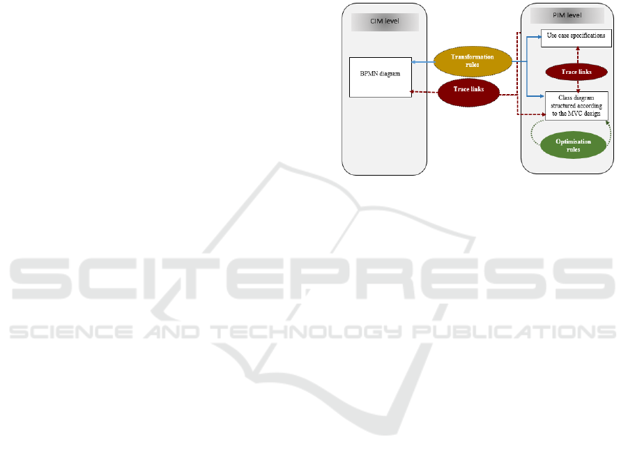
them. Figure.1 shows an overview of our approach.
Figure 1: Overview of the BPtraceUCD Approach.
3.1 Transformation of Pools and Lanes
In this section we propose a set of rules that transform
pools and lanes of a BPMN business process model.
Before applying the rules to the model, we create en
empty CD and an empty UCM.
R1. For each pool p in the BPMN model:
1. If p has a child lane set then create a system
boundary sb in UCM;
2. Traceability: Create a link stereotyped Trace from
p to sb.
Empty lanes/pools do not contain child lane sets.
They are often used to represent internal roles of
organizational units (e.g., Manager, Associate), and
systems (e.g. enterprise application). We transform
them into classes by defining the following rule.
R2. Transform each empty lane/pool p to an
actor in the UCM and to three classes MU ser
p
,
VUser
p
and CU ser
p
as in the MVC pattern. Add
links stereotyped Trace from MUser
p
, VUser
p
and
CU ser
p
to p.
3.2 Transformation of Fragments
A fragment is defined in our previous works (Bouzidi
et al., 2018), (Bouzidi et al., 2017) and (Bouzidi
et al., ) as a sequence of BPMN tasks executed in the
ICEIS 2020 - 22nd International Conference on Enterprise Information Systems
702

same lane, and that handle the same business entity,
i.e. the same item aware element (IAE). Hence, each
fragment f is characterized by its lane, its IAE and
the tasks that compose it.
R3. Transform each fragment f characterized by its
lane, its IAE i and the tasks that compose it into a use
case called Manage
i
.
A fragment may contain gateways, exception events..,
which are important indicators for nominal, alter-
natives or exceptions scenarios of the derived use
case. Therefore, we define R4 that builds scenarios
according to the fragment components. Sometimes,
the input and the output elements of a fragment do
not exhibit the same IAE. Hence, the transformation
and traceability rules defined previously remain valid,
but we should add an association between the classes
corresponding to the input and the output elements.
R4. For each fragment f in a business process model:
1. If f does not contain any gateway or exception
event, create a nominal scenario.
2. If f contains a gateway,
• Create a nominal scenario S1 from the sequence
of tasks involved in the execution of the default
path of the gateway.
• Create an alternative scenario from each se-
quence of tasks involved in the execution of an
alternative path of the gateway.
3. If f contains an exception event:
• Create a nominal scenario S1 from the sequence
of tasks involved in the execution of the default
path of f.
• Create an exception scenario S2 from the se-
quence of tasks involved in the execution of the
path that contains tasks linked to the exception
event.
• Create a dependency relationship from S1 to S2.
4. If f has an input IAE in and an output IAE out,
then:
• Create in the UCM a use case called Manage
in
.
• If in is different from out, then in the CD: (i) ap-
ply R12 to add an association between the en-
tity classes M
in
and M
out
that represent respec-
tively in and out. Its navigability is set from
M
in
to M
out
, (ii) apply R13-R16 to get the mul-
tiplicity of the association, (iii) create classes
called V Manage
in
CManage
in
, stereotyped re-
spectively boundary and control.
• Apply R5.3
• For each automated task (non manual), apply
R10 to add actions to the scenario.
• Traceability: Create links stereotyped Trace (i)
from the use case Manage
in
to f, (ii) from M
in
,
M
out
V Manage
in
and CManage
in
to the use
case Manage
in
.
In a BPMN business process model, IAEs are data
objects, data stores, data inputs, and data outputs.
They are required or produced by BPMN activities
to fulfill their business goals. From a software
development viewpoint, the classes of the domain
CD persistent business entities and correspond to
the IAEs in the BPMN models. The most recent
BPMN version, BPMN 2.0, allows business process
models to be highly detailed. The details include the
specification of persistent data (OMG, 2013) by using
data stores to indicate that data remain beyond the
process life cycle, that is after the process execution
ends (OMG, 2013). To distinguish between persistent
and non-persistent classes we propose to update
persistent properties to true for each class generated
from a data store.
R5. For each IAE i
1. If there is not any class in domain CD traced to i,
then add a class to CD called M
i
. Add the stereo-
type Entity to the class.
2. If i is a data store then set M
i
.persistent to true.
3. If i is a data input/output/object, then create a label
and a text field in the boundary class representing
the fragment that manipulates i, otherwise (i is a
data store) create a combo-box that corresponds
to i.
4. Create associations between M
i
and CManage
i
,
and between CUser and M
i
.
5. Traceability: create links stereotyped Trace from
M
i
to i if it does not already exist.
In BPMN, conditional sequence flows and outgoings
of gateways may be written according to the follow-
ing syntax: IAE.att where att indicates a particular
characteristic of IAE ; for example product.brand.
This semantics is close to the concept of class at-
tributes in UML. Therefore, we define the following
rule:
R6. For each sequence flow label l written according
to the syntax IAE.att where att indicates a particular
characteristic of IAE, generate an attribute called att
in the class MIAE generated from IAE.
Traceability : create a link stereotyped Trace from att
to the label IAE.att.
On the other hand, data object references may specify
different states of the same data object. Hence, we
transform information as follows:
Toward the Alignment and Traceability between Business Process and Software Models
703
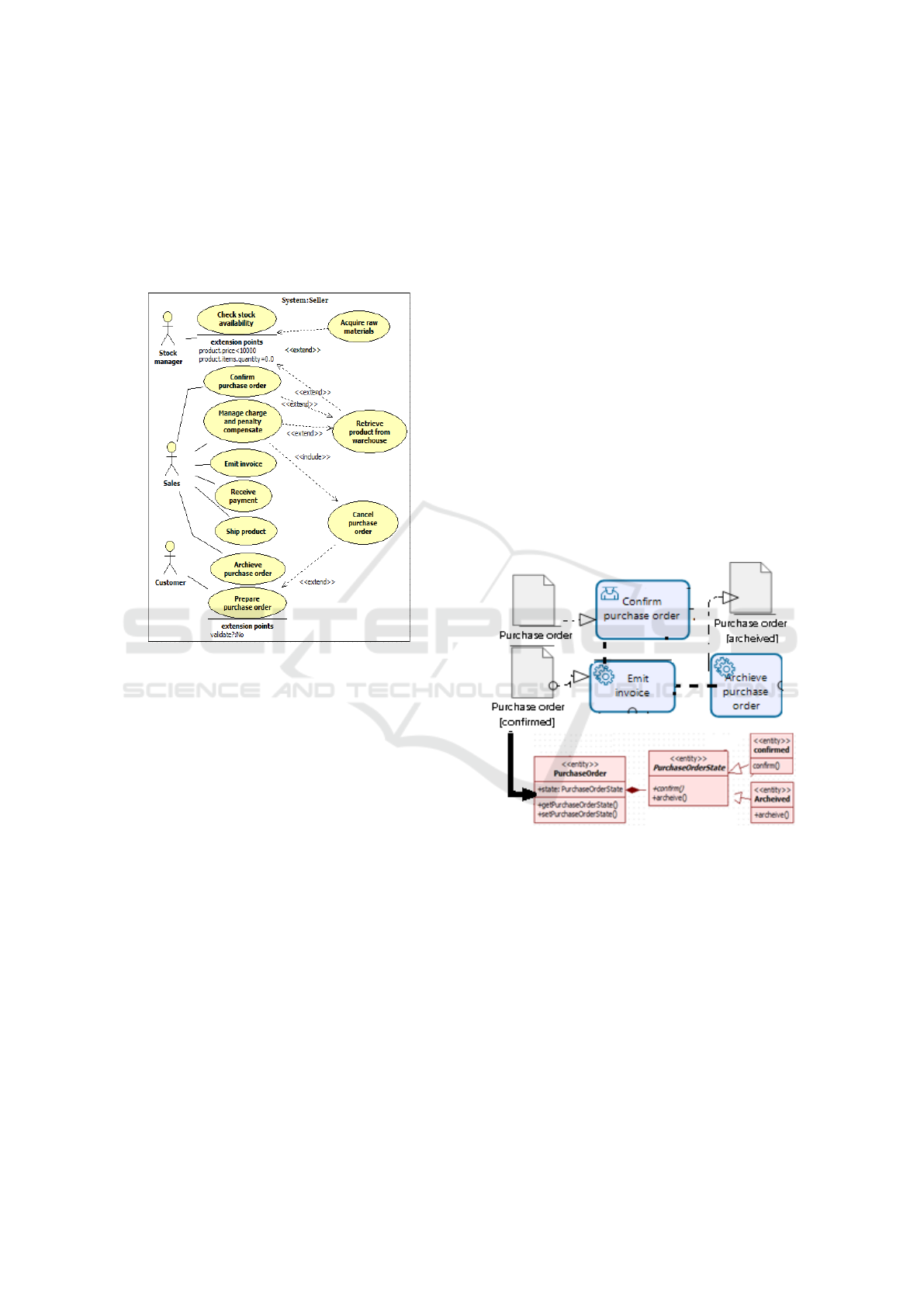
R7. Apply the state design pattern of (Gamma, 1995)
to IAEs with states. This design pattern defines three
classes namely a context class, an abstract class which
name is the concatenation of the name of the data ob-
ject and the word state, and concrete classes. Each
concrete class represents a state of the data object (cf.
Figure.3).
Figure 2: Use Case Diagram Derived from the Online Pur-
chasing and Selling Business Process Model.
3.3 Transformation of Exception and
Signal Events
BPMN defines error, cancel and compensation event
types to trigger exception actions. In UML, classes
stereotyped exception are used to represent exception
situations. Therefore, we propose the following rules:
R8. Transform each exception event into a class
called EventLabel stereotyped exception.
R9.
1. Transform each Signal event in the BPMN model
into a class called SignalEventLabel stereotyped
Signal, and a boundary class called VSignalEvent-
Label.
2. Create an operation named activateEventLabel()
in the class, CManage
i
, that represents the frag-
ment incorporating the signal event (created by
R4.4).
3.4 Transformation of Tasks
In BPMN, tasks meet the UML action semantics, as
they are executable elements in a BPMN process.
Accordingly, we define the following rule:
R10. For each automated task t within a frag-
ment f that manipulates a business entity i;
1. Create an action of a scenario in the use case
Manage
i
, and an operation called t() in the class
CManage
i
;
2. If t is a user task, then create a button in the class
V Manage
i
;
3. Create an association between V Manage
i
and
CManage
i
;
4. Traceability: Create trace links stereotyped trace
from:
• CManage
i
and V Manage
i
to the use case
Manage
i
• V Manage
i
and CManage
i
to t.
Figure 3: Application of Rule R7.
Tasks often need a data input in and/or a data
store (ds) to be executed. We transform this data
to parameters of the operations derived from the tasks.
R11. Transform the input IAEs of a task t into
parameters of the operation t(). The return type of the
operation is generated from the output IAEs.
3.5 Generation of Associations between
Classes
When a task t has an input in, and a different output
IAE out, this means that there is a relationship
ICEIS 2020 - 22nd International Conference on Enterprise Information Systems
704
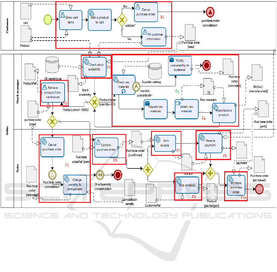
Figure 4: An Online Purchasing and Selling Business Process Model.
between in and out established through t. Thus we
define the following rule.
R12. if a task t has input data in, and different out-
put data out,then create an association between the
classes corresponding to the input and those corre-
sponding to the out if it is not already created by R4.4.
We can deduce association multiplicity from three
BPMN elements : (i) IAEs, (ii) gateways and (iii)
loop task/ rollback sequence flows. BPMN enables
to represent an IAE as a single object (data ob-
ject/input/output/store) or as a data collection. A
single object indicates that the execution of a task
requires or produces a single instance data, while a
collection of data indicates that the data object repre-
sents a collection of instance data. Accordingly, we
define rules R13-R16 to determine the multiplicity of
an association.
R13. If an task t generates an association in the CD,
and if it has as input/output a single object i, the mul-
tiplicity on the side of the class M
i
is (1..1),otherwise
(i is a data collection) the multiplicity is (1..*).
Further, a task may be a loop task, that is a task
with looping behavior. This means that the task may
be performed multiple times. It is also possible to
specify a maximal number of iterations.
R14. If a loop task t is linked to some BPMN
element (exception event, item aware element, etc)
and generates in the CD an association to a class that
derives from that element, then the multiplicity at
this association end is (1..N) where N indicates the
number of iterations. If the number of iterations is
not indicated, the multiplicity is (1..*).
R15. If a task t generates an association in the CD,
and if it has as input/output a single object i and if the
execution of t depends on a condition, for example it
is preceded by an exclusive/inclusive gateway, then
the minimum multiplicity on the side of the class M
i
is 0.
R16. If a task t generates an association in the CD,
Toward the Alignment and Traceability between Business Process and Software Models
705

and if it has input data i , and if t is performed after
a merging gateway, then the minimum multiplicity on
the side of the class M
i
is 0.
3.6 Generation of extends and includes
Relationships
We proved in (Bouzidi et al., 2017) that an includes
relationship between two use cases is generated from
a redundant task t. By applying rule R10, t is trans-
formed into an action in a scenario executed within
a use case uc. Therefore, we propose to replace this
action with the display of the view of a use case uc
t
to indicate that uc invokes uc
t
and uses its action t.
Simultaneously, we create a dependency between the
view classes and the control classes traced with uc and
uc
t
. Furthermore, we create traceability relationships
from the target to the source elements of the transfor-
mation. We denote this transformation rule by R17.
On the other hand, if t is a target ref of an outgo-
ing of a gateway, then we create an extends relation-
ship from uc
t
to uc instead of an includes one. Fur-
thermore, we proved that an extends relationships is
generated from an exclusive or inclusive gateway be-
tween two fragments. Hence, we propose to define
scenarios that display the view of the extending use
case when the extended use case invokes it. We also
create a dependency relationship between the view
and the control classes of the extending and the ex-
tended use cases, and trace links between related ele-
ments. We denote this transformation rule by R18.
4 CASE STUDY
Our illustrative case study (cf.Figure.4) is a typical
business process for online purchasing and selling. It
is decomposed into fragments according to our frag-
ment definition (cf.Figure.4). As the fragments F2,
F3, F6 -F10 are composed of one task, the name
of each one of them is the name of the task it con-
tains. For example, F2 is called Check stock avail-
ability.However, F1, F4, and F5 contain many tasks.
Hence, we manually name them: (i) F1: Prepare a
purchase order; (ii)F4: Acquire raw materials; and
(iii) F5: Manage Charge penalty and compensate.
Figure.2 and Figure.5 depict respectively the gener-
ated use case diagram (UCD) and an extract of the
generated CD organized according to the MVC pat-
tern.
By applying R1 on the pool Seller, a system
boundary called Seller is generated in the UCD, and a
trace link between them is created. Moreover, we ap-
ply R2 on the empty lanes Stock manager and Sales,
and on the empty pool Customer to derive three ac-
tors: Stock manager,Sales and Customer, three enti-
ties called MUser, VUser and CUser, and trace links
from each actor or class to its empty lane/pool.
By applying R5 on the IAEs we add to the CD
the entities PurchaseOrder, Customer, Cart, Prod-
uct, Payment, PenaltyCancellation, StockAvailability,
RawMaterials, SupplierCatalog, and Invoice. R5 also
derives the entities DBWarehouse and SupplierCata-
log and initializes their property persistent to true as
they are generated from data stores.
Further, R7 applied on the data objects Product
and Purchase order produces an abstract class called
ProductState and a concrete class called Packaged,
which are linked by a generalization relationship.
It also adds a composition relationship between the
classes ProductState and Product, an abstract method
called packaged() to the class ProductState, a con-
crete method called packaged() to the concrete class
Packaged, an attribute called state, and its getter and
setter setProductState() in the class Product.
Next, we apply R6 on the sequence flow labels Prod-
uct.price¡100000, and Product.items.quantity=0.0 to
create the attributes price and items.quantity in the en-
tity class Product.
Also, R3 is applied on F1 to create a use
case called Prepare purchase order in the UCD.
Then, R4.4 generates a boundary and a control
class called respectively VPreprarePurchaseOrder
and CPreparePurchaseOrder and an association be-
tween them, and an aggregation from VPreprarePur-
chaseOrder to CUser. R4.4 calls the rules R5.3 to
create associations from the entities Product, Cart
and PurchaseOrder to CPreparePurchaseOrder and
MUser, and R12 to create a n-ary association from the
classes Product and Cart to the entity PurchaseOrder,
(iii) R13 to update the multiplicity of ass to 1..1 on the
side of Product and Cart, and (iv) R15 to update the
multiplicity to 0..1 on the side of PurchaseOrder.
Furthermore, R9 is applied on the signal events
that belong to the fragments F1 and F5 to create a
signal class called PurchaseOrderCancellation and
a boundary class called VPurchaseOrderCancella-
tion. This rule associates the created signal classes
to the classes CPpreparePurchaseOrder and CMan-
agePenaltyAndCompensate.
As the fragment F1 contains a gateway, we ap-
ply R4.2 on F1 to obtain (i) a nominal scenario NS
that contains three actions show cart items, add prod-
uct to cart, fill customer information (NS is consid-
ered as a nominal scenario because it represents a se-
quence of activities involved in the execution of the
default path of an exclusive gateway; (ii) an alter-
native scenario that includes the actions add prod-
ICEIS 2020 - 22nd International Conference on Enterprise Information Systems
706
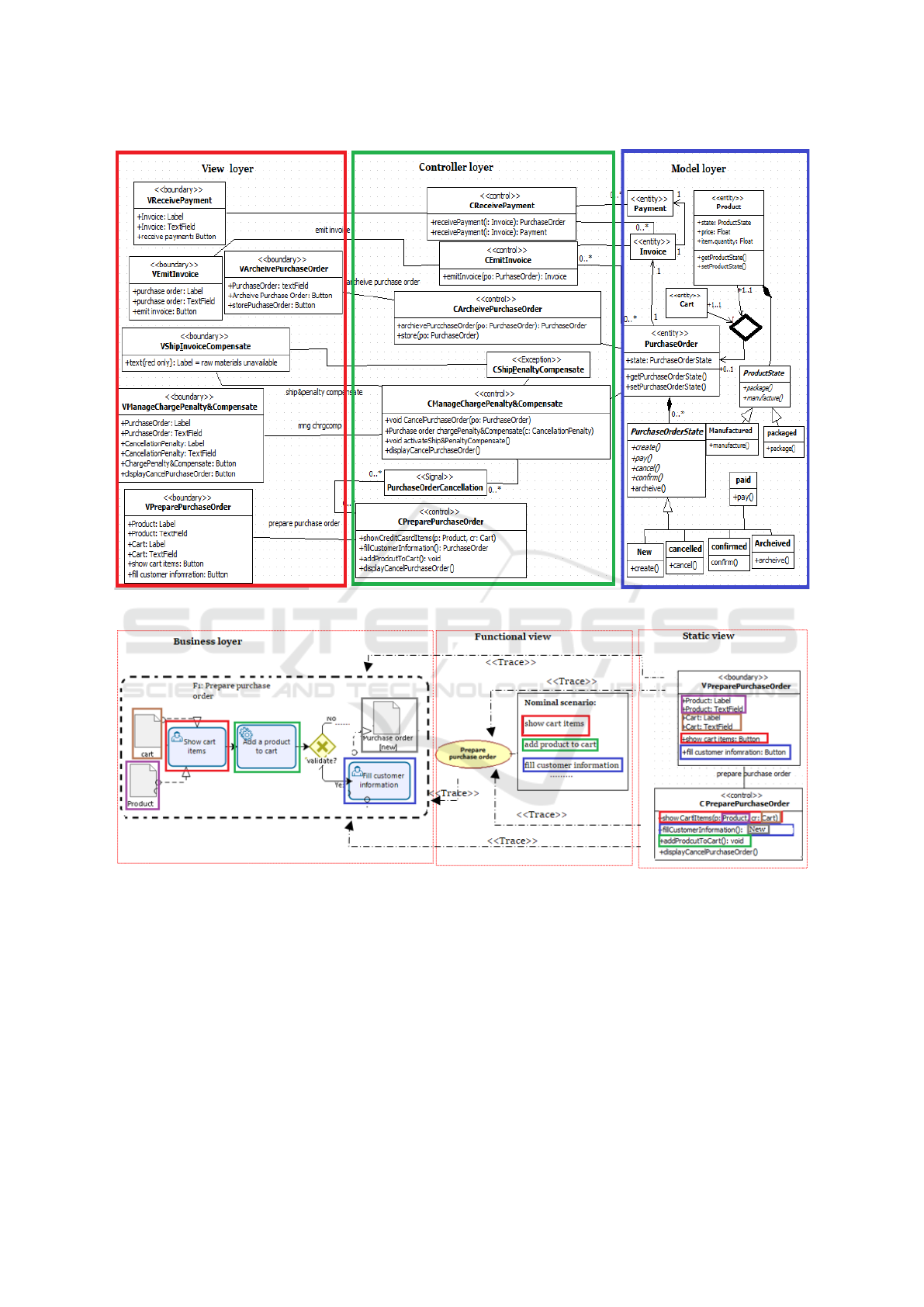
Figure 5: An Extract of the Generated CD Structured According to the MVC Layers.
Figure 6: An Example of Traceability Relationships.
uct to cart, Cancel purchase order. F1 contains
an error event. Therefore, we apply R4.3 and R10
on F1 to create an exception scenario that contains
one action called Cancel purchase order. As the
task Cancel purchase order appears in both F1 and
F5, by applying R17 and R18 on this task, we ob-
tain, in the UCD, a use case called Cancel purchase
order, an extend relationship between Prepare pur-
chase order and Cancel purchase order, and an in-
clude relationship between Manage Charge penalty
and compensate and Cancel purchase order (because
this task is a target ref of a decision gateway). In
addition, R17 creates in the CD (i) a control class
called CCancelPurchaseOrder, and a boundary class
called VCancelPurchaseOrder, (ii) two aggregation
relationships respectively from the class CManage
penalty and compensate to the class VCancel pur-
chase order, and from the class CPreparePurchase-
Order to the class VCancelPurchaseOrder, two but-
tons called display cancel purchase order are added
respectively to VManagePenaltyAndCompensate and
VPreparePurchaseOrder. Further, R17 creates (i)
Toward the Alignment and Traceability between Business Process and Software Models
707

trace links between the use case Prepare purchase
order and the control class CCancelPurchaseOrder
and VCancelPurchaseOrder, and the use case Man-
age charge penalty and compensate, and the classes
CCancelPurchaseOrder and VCancelPurchaseOrder,
(ii) and a trace link Trace respectively between the
task Cancel purchase order, the use case Cancel
purchase order, the extends and includes relation-
ships and the classes CCancelPurchaseOrder and
VCancelPurchaseOrder.
Figure.6 depicts and example of the trace links
established between F1, the use case PreparePur-
chaseOrder, and the classes CPreparePurchaseOrder
and VPreparePurchaseOrder, which maintain them
always aligned. For example,if a new task is
added to F1, then a new action and a new op-
eration should be added restively to the scenar-
ios of the use case PreparePurchaseOrder, and the
classCPreparePurchaseOrder.
5 CONCLUSION
In the current work, we propose, BPtraceUCD, a
semi-automatic transformation and traceability ap-
proach that transforms a BPMN business process
model to a UCM and a CD structured according to
the MVC design pattern. The transformation models
serve as a mean to obtain aligned heterogeneous mod-
els, while the defined traceability links enable to keep
model elements always aligned even if they evolve,
hence reducing the analysis time to recognize sources
of misalignment. Our approach is innovative since
it accounts for both the semantic and structural as-
pects of BPMN and UML specifications in the con-
text of the static and functional viewpoint of the IS.
In addition, it deals with the traceability challenge
between business and software models, and between
software models themselves. Ongoing work is ori-
ented towards broadening the model transformations
and the traceability management, attempting to carry
out the dynamic viewpoint of the IS namely sequence
diagrams.
REFERENCES
Bouzidi, A., Haddar, N., Abdallah, M. B., and Haddar, K.
(2017). Deriving use case models from bpmn models.
In 2017 IEEE/ACS 14th International Conference on
Computer Systems and Applications (AICCSA), pages
238–243. IEEE.
Bouzidi, A., Haddar, N., Abdallah, M. B., and Haddar, K.
(2018). Alignment of business processes and require-
ments through model integration. In 2018 IEEE/ACS
15th International Conference on Computer Systems
and Applications (AICCSA), pages 1–8. IEEE.
Bouzidi, A., Haddar, N., and Haddar, K. Traceabil-
ity and synchronization between bpmn and uml use
case models traceability and synchronization between
bpmn and uml use case models.
Brdjanin, D., Banjac, G., Banjac, D., and Maric, S. (2018).
An experiment in model-driven conceptual database
design. Software & Systems Modeling, pages 1–25.
Christiansen, H., Have, C. T., and Tveitane, K. (2007).
From use cases to uml class diagrams using logic
grammars and constraints. In RANLP, volume 7,
pages 128–132.
Cruz, E. F. and Cruz, A. M. R. (2018). Deriving integrated
software design models from bpmn business process
models.
Gamma, E. (1995). Design patterns: elements of reusable
object-oriented software. Pearson Education India.
Khlif, W., Elleuch, N., Alotabi, B.-A., and Hanene (2018).
Designing bp-is aligned models: An mda-based trans-
formation methodology.
Liew, P., Kontogiannis, K., and Tong, T. (2004). A frame-
work for business model driven development. In 12
International Workshop on Software Technology and
Engineering Practice (STEP’04), pages 8–pp. IEEE.
OMG (2006). The Fast Guide to Model DrivenArchitec-
ture[Online]. OMG.
OMG (2013). Business Process Model and Notation
(BPMN)Version 2.0.2. OMG.
Rhazali, Y., Hadi, Y., and Mouloudi, A. (2016). Model
transformation with atl into mda from cim to pim
structured through mvc. Procedia Computer Science,
83:1096–1101.
Rodr
´
ıguez, A., de Guzm
´
an, I. G.-R., Fern
´
andez-Medina, E.,
and Piattini, M. (2010). Semi-formal transformation
of secure business processes into analysis class and
use case models: An mda approach. Information and
Software Technology, 52(9):945–971.
Sepulveda, C., Cravero, A., and Cares, C. (2017). From
business process to data model: a systematic mapping
study. IEEE Latin America Transactions, 15(4):729–
736.
ICEIS 2020 - 22nd International Conference on Enterprise Information Systems
708
