
Novel Fabrication Method of Minute Cylindrical Structures Such as
Stents using Lithography, Etching, and Chemical Polishing
Toshiyuki Horiuchi
*
, Kaiki Ito
*
, Jun-ya Iwasaki
*
and Hiroshi Kobayashi
*
Tokyo Denki University, 5 Senju-Asahi-cho, Adachi-ku, Tokyo, Japan
Keywords: Fabrication Method, Cylindrical Structure, Stent, Lithography, Chemical Etching, Chemical Polishing,
Rotary Scan-projection Exposure, Stainless-steel Pipe.
Abstract: Applicability of characteristic subtractive processes of stainless-steel pipes to fabrication of minute structures
such as stents was demonstrated. Pipes with an outer diameter of 2 mm, a thickness of 50 µm, and a length of
50 mm were coated with a resist PMER N-CA3000 PM in approximately 10 µm thick in 20 mm area at the
tip parts of pipes. Next, stent-like mesh patterns composed of 30 rhombuses on an ordinary flat film reticle
were replicated on a pipe using a rotary scan-projection exposure system, in which patterns were precisely
and homogeneously replicated by synchronously scanning the reticle linearly in perpendicular to the pipe axis
and rotating the pipe at a constant speed. All the patterns on the reticle were continuously replicated during
the pipe was rotated 360º. After printing the stent-like mesh patterns, the pipes were processed in two steps.
In the first step, they were wetly etched in FeCl
3
aqueous solution, and in the second step, they were
chemically polished in a chemical compound on the market. As a result, a stent-like meshed pipe with mesh
widths of 83±6 µm was precisely fabricated.
1 INTRODUCTION
Diseases of blood vessels are one of the typical
illnesses in the present age. Choked, damaged, or
adhered vessels prevent the supply of fresh blood to
organs and tissues, and cause the necrosis and
degradation of organs. For this reason, effective
medical treatments have to be given in the early
stages of diseases.
Insertions of stents are considered as prospective
treatments (Varghese, 2015) (Rahal, 2014) (Caiazzo,
2015). Stents are cylindrical components with net-
like structures, and have appropriate elasticity and
rigidity. When the stents are inserted in blood vessels,
they should be folded or shrunk in diameter. On the
other hand, once they are inserted, they have to
support the blood vessels from inside and secure the
blood paths (Tammareddi, 2016).
For this reason, various methods have been
researched and developed for fabricating stents
superior in usability, functionality, and mechanical
properties. Knitting of wires or fibres (Rebelo, 2015)
and cutting of metal pipes using laser beams
(Kesavan, 2013) (Ando, 2017) (Nishi, 2013) are
*
https://www.dendai.ac.jp/en/graduate/
typical methods.
On the other hand, the authors have researched on
lithography systems for patterning on fine cylindrical
specimens such as pipes, wires, shafts, and others. For
this reason, as a typical application of the system and
related lithography and etching technologies,
fabrication of stent-like structures is investigated
here.
Generally speaking, patterning accuracies of
lithography and etching are higher than laser beam
cutting. In addition, it is expected that roughness of
part-edges obtained by lithography and etching is
improved by serially adding chemical polishing after
the etching. Based on these considerations, this
research has been performed.
As a lithography tool, a handmade rotary scan-
projection exposure system (Horiuchi, 2015)
(Horiuchi, 2016) is used. In this system, patterns on a
flat reticle in an oblong slit area is projected on a
cylindrical ridge of specimen pipe. When the reticle
is linearly scanned across the slit and the pipe is
rotated around its axis synchronously, patterns on the
reticle are continuously replicated on the cylindrical
surface of the pipe.
Horiuchi, T., Ito, K., Iwasaki, J. and Kobayashi, H.
Novel Fabrication Method of Minute Cylindrical Structures Such as Stents using Lithography, Etching, and Chemical Polishing.
DOI: 10.5220/0008997201690175
In Proceedings of the 13th International Joint Conference on Biomedical Engineering Systems and Technologies (BIOSTEC 2020) - Volume 1: BIODEVICES, pages 169-175
ISBN: 978-989-758-398-8; ISSN: 2184-4305
Copyright
c
2022 by SCITEPRESS – Science and Technology Publications, Lda. All rights reserved
169
Lithography tools for printing on cylindrical pipes
have not been commercially available. Although
various ideas have been reported (Lee, 2011) (Haoa,
2011) (Lim, 2014), performances comparable with or
superior to those of our system have never been
shown for printing aimed complicated patterns.
After the pipes with stent-like patterns of resist are
etched in an aqueous solution of ferric chloride
(FeCl
3
), original shapes of stent-like meshed pipes
were fabricated. Fabrication methods up to this stage
have been already developed in the past researches of
authors (Ito, 2017) (Horiuchi, 2019).
However, in the past researches, the minimum
mean mesh width was 109 µm, and it was difficult to
reduce the widths without making locally broken
parts. For this reason, as a new idea, chemical
polishing process is added here. By polishing the
meshed pipes slowly and carefully, the mesh widths
are reduced down to 83 µm. The roughness of the
meshes is also improved.
2 FABRICATION PROCESS OF
STENT-LIKE MESHED PIPES
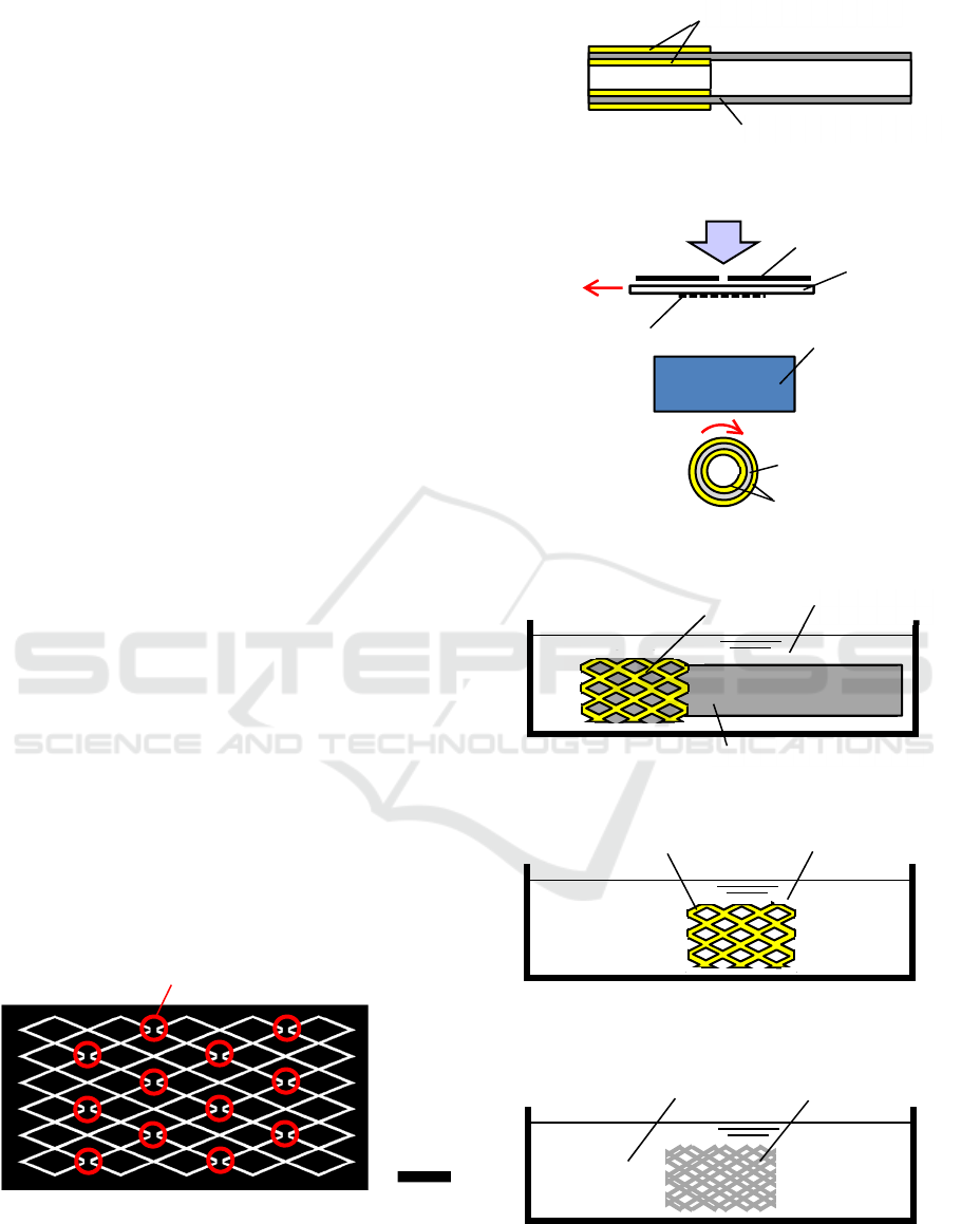
Meshed patterns were designed by connecting
rhombuses at their corners sequentially. The
rhombuses were arrayed 5 in the axial direction and 6
in the circumferential direction. Figure 1 shows the
reticle patterns designed by extending the aimed
meshed pipe shape. After 5×6=30 rhombuses were
regularly arrayed, connections at 12 corners were
intentionally separated for giving flexibility or
deformability to the meshed pipe. The rhombus
pattern width was 130 µm.
It was planned to fabricate this structure according
to the following processes, as shown in Figure 2. At
first, the meshed patterns of resist were printed on
Figure 1: Reticle patterns designed for printing stent-like
rhombus mesh.
(a) Resist coating
b) Rotary scan-projection exposure
(c) Development
(d) Etching in ferric chloride
(e) Chemical Polishing
Figure 2: Processes for fabricating the aimed structure.
Stainless-steel pipe
Resist
Exposure light
Slit
Reticle
Patterns
Linear scan
Stainless-steel pipe
Rotation
Resist
1
Projection lens
Etchant
Resist Developer
Stainless-steel pipe
Meshed pipe with resist
Polishing chemicals
Polished pipe
2 mm
Intentionally separated parts
BIODEVICES 2020 - 13th International Conference on Biomedical Electronics and Devices
170
SUS304 stainless-steel pipes using the rotary scan-
projection lithography. The contents of SUS304 are
shown in Table 1. The other part of the alloy is iron
(Fe). Main components are Fe, Cr, and Ni.
Table 1: Contents of SUS304 except iron.
Element Content
Cr 18.00-20.00
Ni 8.00-10.50
Mn ≤ 2.00
Si ≤ 1.00
C ≤ 0.08
P ≤ 0.045
S ≤ 0.030
In this lithography system, patterns on the reticle
were replicated on a pipe coated with a resist film
during the flat reticle was linearly scanned in the
horizontal direction, and rotating a pipe 360º
synchronously around its axis.
Next, the pipe was etched in an aqueous solution
of FeCl
3
using the mesh patterns of resist as etching
masks. After the etching, meshed pipe with the still
remained resist patterns on the outer surface was
polished in a chemical liquid compound on the
market.
Although the resist was almost removed during
the polishing, it remained partially. For this reason,
the polished pipe was cleaned finally by dipping in
acetone and adding ultra-sound wave vibration.
By these processes, the meshed pipes were
smoothed and homogeneously thinned. As a result,
precisely meshed pipes were obtained.
3 RESIST PATTERN PRINTING
Using the reticle, meshed patterns were printed on
SUS304 stainless-steel pipes with outer and inner
diameters of 2 and 1.9 mm and a length of 50 mm.
The thickness of the pipe wall was 50 µm. As a resist,
the negative PMER N-CA3000 PM (Tokyo Ohka
Kogyo) was used, and coated in approximately 10 µm
thick in 20 mm area from the tip of a pipe one by one.
Although positive resists had high resolution, it
was worried that the exposure doses between
sensitized or not would change critically, and the
exposure dose margin for the patterning became
small. In addition, it was feared that the vague
exposure influenced by the slit width and the pipe
curvature led up to the contrast degradation of pattern
images, and notable fluctuation of pattern widths and
thicknesses occurred. In contrast, widths and
thicknesses of the negative resist patterns tended to
saturate if the exposure dose was sufficiently given.
For this reason, it was thought that good patterning
homogeneity would be obtained. Besides, negative
resists with high transmittance were commercially
available, and thick resist patterning durable for long-
time etching with high speed stirring was applicable.
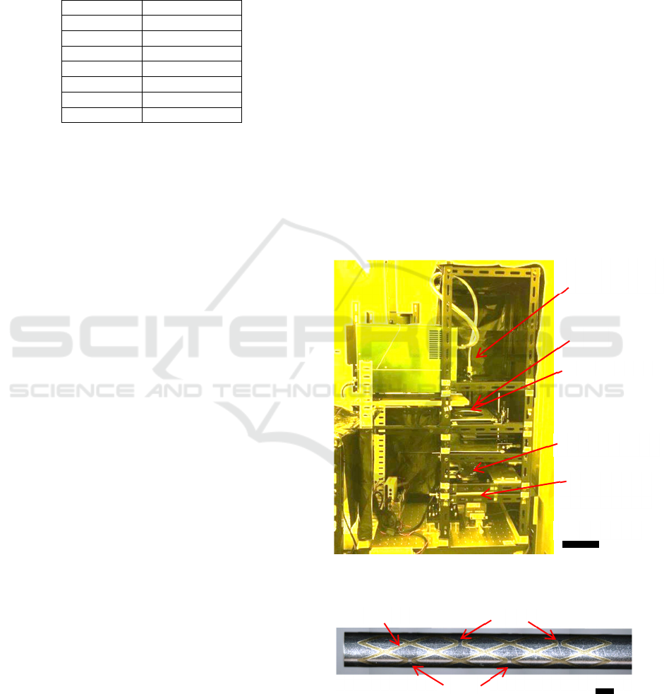
The reticle patterns were printed using a
handmade exposure system, as shown in Figure 3.
The typical exposure time for rotating the pipe 360º
was 30 s.
An example of resist patterns on a pipe is shown
in Figure 4. Mesh patterns are finely printed.
Measurement results of pattern widths are shown in
Figures 5 and 6. They show the width distribution in
the axial and circumferential directions, respectively.
It is known that pattern widths are very homogeneous.
The 3σ deviation was 12.0 µm.
However, the mean width was 208 nm, and very
wide comparing with the reticle pattern width of 130
µm. It was considered that this width increase was
caused by the following reasons. One reason is that
the actual projection ratio was not 1 but 1.13.
Figure 3: Handmade rotary scan-projection exposure
system.
Figure 4: An example of resist patterns on a pipe.
Rod lens for
illumination
Slit
Reticle
Projection lens
Stainless-
steel pipe
100 mm
1 mm
Gaps
Gaps
Resist
Novel Fabrication Method of Minute Cylindrical Structures Such as Stents using Lithography, Etching, and Chemical Polishing
171
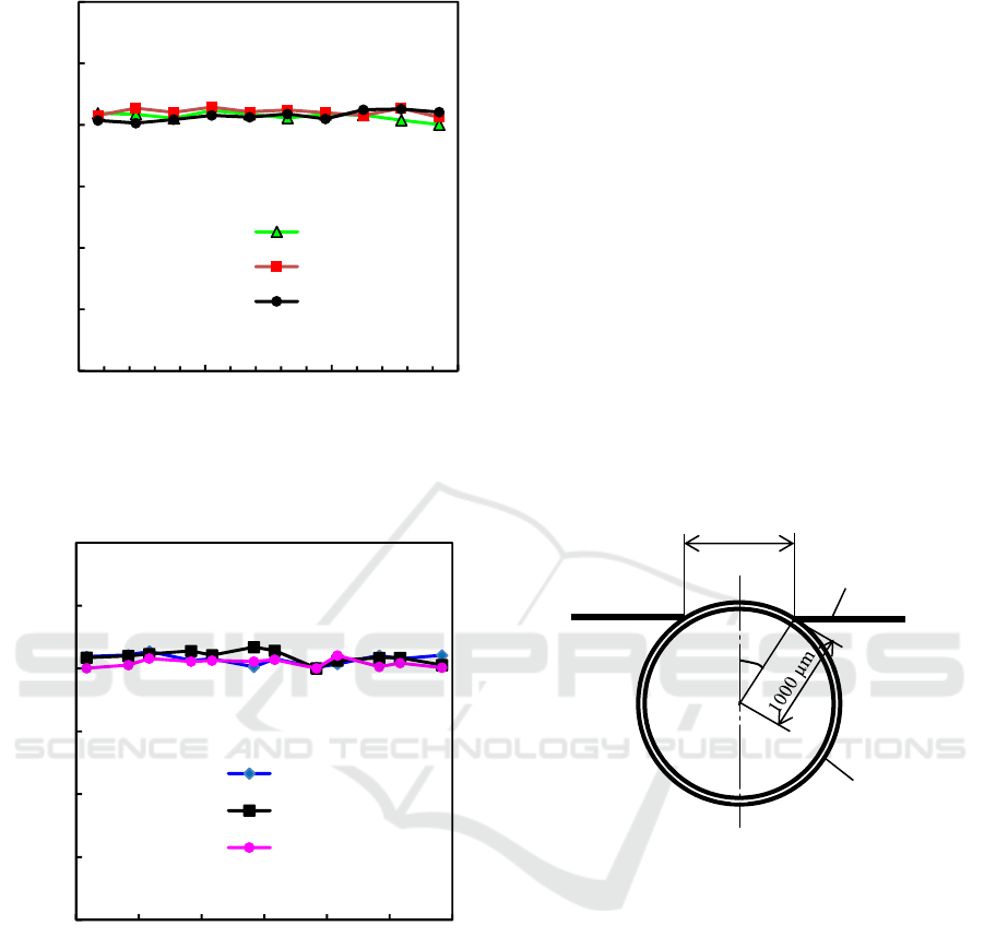
Figure 5: Width fluctuation of mesh resist patterns in the
axial direction.
Figure 6: Width fluctuation of mesh resist patterns in the
circumferential direction.
Accordingly, the projected width of mesh pattern
becomes 130×1.13=147 µm. In addition, because the
slit width was 800 µm and the mesh patterns were
projected on the curved surface of the pipe, the
pattern widths were slightly widened. Besides,
projected positions were also shifted at the both
outside ends of the slit. Since the slit width of 800 µm
was also magnified to 800×1.13=904 µm, the angle θ
between the ends A and B of the projected area from
the centre line are calculated referring to Figure 6,
θ=sin
-1
(0.904/2) =26.9º. (1)
Therefore, the pattern width printed at the both
outside ends of the slit becomes 147 µm /cos
θ
=165
µm.
On the other hand, the arc length L of the
circumference MB of the pipe in the angle of
θ
is
calculated to be
L=(26.9×π/180) ×1000 µm = 469 µm. (2)
Accordingly, the pattern at B is printed shifting
469-(904/2) =17 µm to the right outside. In contrast,
the pattern at A is printed shifting 17 µm to the left
outside. Accordingly, pattern width including the
vaguely exposed parts become 165+17+17=199 µm.
For this reason, if the resist is exposed sufficiently to
stabilize the pattern widths, the widths become more
than this width, and the widths shown in Figures 4 and
5 are within the reasonable range.
Figure 7: Figure for considering the pattern position shift
and size change on the curved pipe surface.
4 ETCHING AND CHEMICAL
POLISHING
Patterned pipes were etched in an aqueous solution of
FeCl
3
( Sanhayato, H-1000A ) for 25 min at 40-
45ºC. The etchant was stirred by a propeller stirrer
rotating at 250 rpm. After the etching, the pipes were
rinsed by pure water. The patterns on the pipe surface
were remained as they were.
Next, etched pipes with the remained resist
patterns were chemically polished in a chemical
compound on the market (Sasaki Chemical, S-250)
heated on a hotplate at 93-95 ºC for 1.5 min. During
the polishing, the pipe was held by an L-shape tool
handmade with a hard plastic material, and moved in
Image of slit
B
A
θ
904
µ
m
O
M
Pipe
0
50
100
150
200
250
300
0 5 10 15
Series1
Series2
Series3
Resist pattern width (µm)
Position from the tip end (mm)
10
130
250
Rotation angle of the pipe (deg)
0
50
100
150
200
250
300
0 60 120 180 240 300 360
Series1
Series2
Series3
Resist pattern width (µm)
Rotation angle of the pipe (deg)
0.75
6.75
14.25
Position from the tip end (mm)
BIODEVICES 2020 - 13th International Conference on Biomedical Electronics and Devices
172
the chemical compound by swinging it using the tool.
The polishing was advanced at a speed of
approximately 7 µm/min in width directions.
On the other hand, the resist began to be peeled
off from approximately 40 s after beginning the
polishing. Therefore, it was supposed that the
polishing was advanced in the thickness direction also
after that.
After the polishing, the pipes were rinsed by pure
water. However, because resist fragments remained
on the polished pipes were observed, they were
removed by washing the pipes in acetone with ultra-
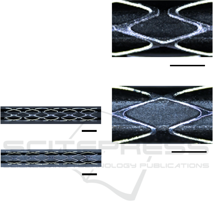
sonic vibration. Figure 8 compares stent-like meshed
pipes with and without the chemical polishing. In the
case of a pipe etched only by FeCl
3
, obtainable mean
mesh width was 109μm, as shown in Figure 8(a). In
contrast, when the chemical polishing was added, the
mesh-part width was reduced to 83 μm, as shown in
Figure 8(b).
(a) Pipe meshed by only etching in FeCl
3
.
(b) Pipe finished by polishing in chemicals.
Figure 8: Comparison of meshed-pipe preciseness between
with and without finishing by chemical polishing.
Besides, side wall roughness of the meshed parts
was decreased from around 10 µm to 5 µm, as
compared in Figure 9. It is known that the chemically
polished pipes became smooth and sheeny.
In Figures 8 and 9, photographs of meshed pipes
were taken by inserting a black hexagonal wrench
into the meshed pipes. For this reason, only the front
sides of the structures are shown. The vague
horizontal lines in the photographs are the ridges of
wrenches.
Next, to investigate the width fluctuation of stent-
like meshed parts, mesh widths were measured at 4
sides of all 30 rhombuses. Measured width
distributions are shown in Figures 10 and 11. It was
clarified that the widths were almost homogeneous in
both axial and circumferential directions. The 3σ
deviation of width was 6.2 µm. This fluctuation
(a) Pipe meshed by only etching in FeCl
3
.
(b)
Pipe finished by polishing in chemicals.
Figure 9: Comparison of meshed-pipe roughness between
with and without finishing by chemical polishing.
was far smaller than the 3σ deviation value of 13.5
µm obtained in the pipe shown in Figure 8(a) finished
without adding the chemical polishing in the
compound. In addition to the fact that the mean width
was reduced, width fluctuation was noticeably
decreased.
Components of S-250 are not made public. In the
instruction manual, it is written that the chemical is
composed of strong acid and gloss finisher. Judging
from the description of “nitrous acid gas is
generated”, it is supposed that the main strong acid is
nitric acid. The gloss polisher is a dangerous goods
class 4/class 2 petroleum. Pipe surfaces etched only
by FeCl
3
without the resist was rough and not sheeny.
The surface smoothness was inferior to that obtained
by the polishing.
The authors thought that the distortions of pattern
sizes and the shifts of printed positions could be
reduced by using a slit with a narrower width.
However, the illumination optics had to be improved
for collecting the light flux in the slit efficiently,
2 mm
2 mm
1 mm
1 mm
Novel Fabrication Method of Minute Cylindrical Structures Such as Stents using Lithography, Etching, and Chemical Polishing
173
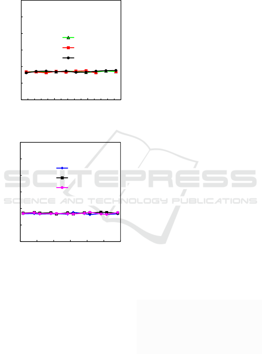
Figure 10: Width fluctuation of meshes in the axial
direction after the chemical polishing.
Figure 11: Width fluctuation of meshes in the
circumferential direction after the chemical polishing.
because the exposure time was lengthened. In
addition, since the meshed part widths were largely
thinned by the undercut during the etching and
polishing, printed wide mesh patterns were rather
preferable.
Mechanical performance of the polished stent-like
parts have not been investigated yet, and should be
clarified hereafter. However, it was checked in the
past research that a similar meshed pipe without
polishing kept deformation linearity and elasticity
when the pressing force was less than 0.6 N at least.
Because the axial cross section of the stent-like part
is 2×15=30 mm
2
, pressing force of 0.6 N corresponds
to the differential blood vessel pressure of 0.6/30
N/mm
2
=0.02 MPa=200 hPa=150 mmHg, which is
approximately the maximum differential blood vessel
pressure.
5 CONCLUSIONS
Stent-like meshed pipes were successfully fabricated
by a novel method using lithography, wet etching and
chemical polishing. As a raw material, stainless-steel
SUS304 pipes with outer and inner diameters of 2 and
1.9 mm, respectively, were used.
At first, resist patterns were printed on a pipe
surface using a rotary scan-projection exposure
system. In the system, stent-like mesh patterns on a
reticle were continuously replicated on a resist film
coated on a pipe by synchronously scanning the
reticle linearly and rotating the pipe at a constant
speed. After the patterning, pipes with stent-like resist
patterns were etched in an aqueous solution of FeCl
3
.
Next, the meshed pipes were chemically polished
using a chemical compound on the market.
As a result, very fine meshed parts with a mean
width of 83 µm were obtained. Jogged edges of the
etched pipes were smoothed, and the 3σ deviation of
mesh widths was largely reduced from 13.5 µm to 6.2
µm. It was demonstrated that the subtractive process
of stainless-steel pipes would be applicable to
fabrication of minute complicated structures such as
stents.
ACKNOWLEDGEMENTS
This work was partially supported by JAPS
KAKENHI Grant Number 17K05021, the grants
from JI Engineering, and the grants from Shonan
Instruments.
REFERENCES
Ando, K., Ishii, K., Tada, E., Kataoka, K., Hirohata, A.,
Goto, K., Kobayashi, K., Tsutsui, H., Nakahama, M.,
Nakashima, H., Uchikawa, S., Kanda, J., Yasuda, S.,
Yajima, J., Kitabayashi, H., 2017. Prospective multi-
center registry to evaluate efficacy and safty of the
newly developed diamond-like carbon-coated cobalt-
chromium coronary stent system, Cardiovascular
Intervention and Therapeutics, Vol. 32, Issue 3, 225–
232.
Rotation angle of the pipe (deg)
0
50
100
150
200
250
300
0 5 10 15
Series1
Series2
Series3
10
130
250
Mesh width (µm)
Position from the tip end (mm)
0
50
100
150
200
250
300
0 60 120 180 240 300 360
Series1
Series2
Series3
0.75
6.75
14.25
Position from the tip end (mm)
Mesh width (µm)
Rotation angle of the pipe (deg)
BIODEVICES 2020 - 13th International Conference on Biomedical Electronics and Devices
174

Caiazzo, G., Fabris, K. E., Serdoz, O., Mattesini, A., Foin,
N., Rosa S. D., Indolfi. C., Mario, C. D., 2015. Absorb
bioresorbable vascular scaffold: What have we learned
after 5 years of clinical experience? International
Journal of Cardiology Vol. 201, 129–136.
Haoa, X., Wang, L., Wanga, O., Guoa, F., Tanga, Y., Dinga,
Y., Lua, B., 2011. Surface micro-texturing of metallic
cylindrical surface with proximity rolling-exposure
lithography and electrochemical micromachining.
Applied Surface Science. Vol. 257, 8906-8911.
Horiuchi, T., Fujii, H., Yasunaga, K., 2015, Lithography
onto Surfaces of Fine-Diameter Pipes Using Rotary
Scan-Projection Exposure. Journal of Photopolymer
Science and Technology, Vol. 28, No. 2, 273-278.
Horiuchi, T., Furuhata, T., Muro., 2016. Synchronous scan-
projection lithography on overall circumference of fine
pipes with a diameter of 2 mm. Japanese Journal of
Applied Physics, Vol. 55, 06GP13, 1-6.
Horiuchi, T., Ito, K., Kobayashi, H., Yanagida, A., 2019.
Investigation on stainless-steel stents fabricated using
projection lithography and wet etching, 2
nd
EUROPEAN BIOSENSOR SYMPOSIUM (EBS
2019), FLORENCE, ITALY, 240.
Ito, K., Suzuki, Y., Horiuchi, T., 2017. Fabrication of
Cylindrical Micro-Parts Using Synchronous Rotary
Scan-Projection Lithography and Chemical Etching.
Proceedings of SPIE, Vol. 10454, 1045410, 1-6.
Kesavan, S., Strange, J. W., Johnson, T. W., Flohr-Roese,
S., Baumbach, A., 2013. First-in-man evaluation of the
MOMO cobalt-chromium, carbon-coated stent,
EuroIntervention, Vol. 8, No. 9, 1012-1018.
Lee, D., Hiroshima, H., Zhang, Y., Itoh, T., Maeda, R.,
2011. Cylindrical projection lithography for microcoil
structures. Microelectronic Engineering. Vol. 88,
2625–2628,
Lim, H., Choi, K., Kim, G., Lee, S., Park, H., Ryu, J., Jung,
S., Lee, J., 2014. Roll-to-roll nanoimprint lithography
for patterning on a large-area substrate roll.
Microelectronic Engineering. Vol. 123, pp. 18–22,
2014.
Nishi, S., Nakayama, Y., Ishibashi-Ueda, H., Yoshida, M.,
Yonetani, H., 2013. Treatment of rabbit carotid
aneurysms by hybrid stents (microporous thin
polyurethane-covered stents). Preservation of side-
branches, Vol. 28, issue: 7, 1097-1104.
Rahal, J. P., Dandamudi, V. S., Heller, R. S., Safain, M. G.,
Malek. A. l., 2014. Use of concentric Solitaire stent to
anchor Pipeline flow diverter constructs in treatment of
shallow cervical carotid dissecting pseudoaneurysms,
Journal of Clinical Neuroscience Vol. 21, 1024–1028.
Rebelo, R., Vila, N., Fangueiro, R., Carvalho, S., Rana, S.,
2015. Influence of design parameters on the mechanical
behavior and porosity of braided fibrous stents,
Materials and Design. Vol. 86, 237–247.
Tammareddi, S., Sun, G., Li, Q., 2016. Multiobjective
robust optimization of coronary stents, Materials and
Design. Vol. 90, 682–692.
Varghese, T. G., Thomas, S. C., Revanka, V. R., 2015.
Emergency stenting of unprotected left main coronary
artery occlusion using bare metal stent with good long-
term results, -A case report-, Journal of Indian college
of cardiology, Vol. 5, 345-348.
Novel Fabrication Method of Minute Cylindrical Structures Such as Stents using Lithography, Etching, and Chemical Polishing
175
