
Artificial Neural Networks and Reinforcement Learning for
Model-based Design of an Automated Vehicle Guidance System
Or Aviv Yarom
a
, Soeren Scherler
b
, Marian Goellner
c
and Xiaobo Liu-Henke
Ostfalia University of Applied Sciences, Salzdahulmer Str. 46/48, 38302 Wolfenbuettel, Germany
Keywords: Artificial Intelligence, AI, Artificial Neural Networks, ANN, Genetic Algorithm, Reinforcement Learning,
Automated Vehicle Guidance, Automated Lateral Guidance, Automated Driving, ADAS.
Abstract: This paper presents the model-based development of a function for lateral control of an automated vehicle
using Artificial Neural Networks (ANN) and Genetic Algorithms (GA). After an explanation of the method-
ology used and a summary of the state of the art for automated lateral control as well as for ANNs and rein-
forcement learning, the driving function is designed in the form of a functional structure. This is followed by
a detailed description of the model-based design and validation process of the AI system. Finally, the function
for automated lateral guidance in combination with a superior intelligent route management is verified and
optimized in a pilot application.
1 INTRODUCTION
Automated driving and the associated digitalization
and cross-linking of the cyber-physical traffic system
(CPTS) are important focal points of modern research
and development projects aimed to make mobility
safer, more environmentally friendly and more com-
fortable. Autonomous driving shows new applica-
tion-specific usage scenarios that lead to innovative
technologies if they are considered at an early stage
in vehicle development. For this reason, electric, driv-
erless, application-specific vehicle concepts are being
developed within the joint project "autoMoVe" (Dy-
namically Configurable Vehicle Concepts for a Use-
specific Autonomous Driving) funded by the Euro-
pean Fund for Regional Development (EFRE).
The various advanced driver assistance systems
(ADAS) used today are usually based on conven-
tional algorithms for information processing or on tra-
ditional methods of control theory. With increasing
automation of driving operations, the requirements
for safety and reliability in the various unpredictable
situations of the complex CPTS continue to rise,
which these proven methods can no longer meet
(Vishnukumar, 2017). Therefore, the subproject "au-
toEVM" (Holistic Electronic Vehicle Management
a
https://orcid.org/0000-0001-5627-4199
b
https://orcid.org/0000-0003-0578-3203
c
https://orcid.org/0000-0002-5577-2740
for Autonomous Electric Vehicles) aims the model-
based design of innovative intelligent algorithms and
functions for autonomous driving. Artificial intelli-
gence (AI) is a key technology for the many domains
involved in the development, testing and deployment
of intelligent, automated vehicles.
A primary constituent of autonomous or automat-
ed driving is the control of the planar dynamics, i.e.
the adjustment of the driving speed and steering an-
gle. In this contribution, the model-based design of a
function based on Artificial Neural Networks (ANN)
and Genetic Algorithms (GA) for the automated lat-
eral guidance of a vehicle is exemplarily presented.
2 METHODOLOGY
Due to the constantly increasing complexity and
cross-linking of mechatronic systems, a structured
and holistic design methodology is unavoidable. In a
top-down process, a complex overall system is mod-
ularized and hierarchically structured into intelligent,
encapsulated subsystems consisting of mechatronic
components with defined interfaces. Figure 1 shows
an example of the mechatronic structuring of the re-
Yarom, O., Scherler, S., Goellner, M. and Liu-Henke, X.
Artificial Neural Networks and Reinforcement Learning for Model-based Design of an Automated Vehicle Guidance System.
DOI: 10.5220/0008995407250733
In Proceedings of the 12th International Conference on Agents and Artificial Intelligence (ICAART 2020) - Volume 2, pages 725-733
ISBN: 978-989-758-395-7; ISSN: 2184-433X
Copyright
c
2022 by SCITEPRESS – Science and Technology Publications, Lda. All rights reserved
725
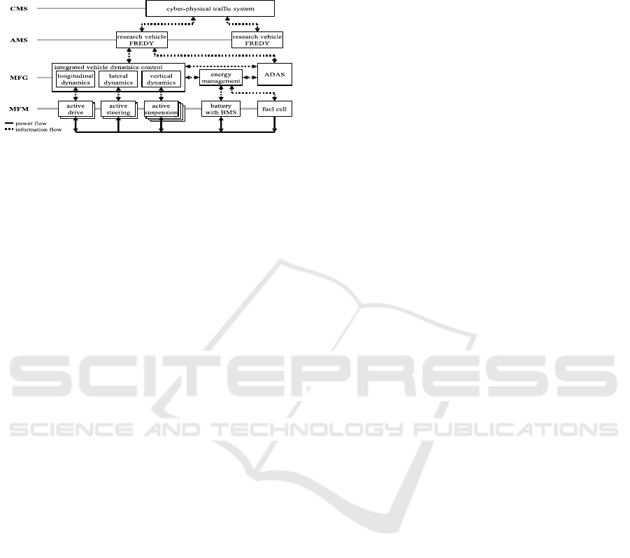
search vehicle FREDY (Function Carrier for Regen-
erative Electromobility and Vehicle Dynamics) with
four hierarchical levels based on (Scherler, 2019).
Figure 1: Mechatronic structuring of FREDY.
The lowest hierarchical level is made up of mech-
atronic function modules (MFM), which consist of
mechatronic systems that cannot be further subdi-
vided. They contain a mechanical structure, sensors,
actuators and information processing. Each encapsu-
lated MFM has a defined functionality and describes
the dynamics of the system. By coupling several
MFMs and adding an information processing, mech-
atronic function groups (MFG) are set up. MFGs en-
able the realization of higher-value functions by using
the subordinate MFMs. The combination of MFGs
leads to autonomous mechatronic systems (AMS),
e.g. the autonomous vehicle FREDY. By cross-link-
ing several AMS a cross-linked mechatronic system
(CMS), in this case a CPTS, is created.
After the hierarchical structuring, the mechatronic
composition takes place in a bottom-up procedure.
Starting with the lowest hierarchy level, each module
is designed, validated and successively integrated into
the overall system in a model-based, verification-ori-
ented process.
3 STATE OF THE ART
3.1 Automated Lateral Guidance
Modern ADAS for automated lateral guidance re-
quire vehicle sensors for determining the direction of
movement as well as environmental sensors, e.g. to
detect the course of the road or to calculate the devi-
ation from the centre of the lane (Bartels, 2015).
Self-localization is usually achieved by visual ori-
entation along the road markings. Currently used al-
gorithms are based either on lane color characteristics
or on manually programmed lane models. Such con-
ventional methods of image analysis achieve good re-
sults under suitable lighting conditions and clearly
visible road markings, e.g. on motorways. But they
are also very computationally intensive and reach
their limits in the case of disturbances such as poor
visibility as well as dirty, damaged or complex road
marking situations (Zang, 2018). If the position of the
vehicle in the lane cannot be clearly determined the
driver must take over the steering himself. Therefore,
depending on the manufacturer, modern lateral guid-
ance assistants are only enabled above 60 km·h
-1
(Bartels, 2015). As a result, these systems can only be
used on country roads and motorways. Their use in
complex inner-city scenarios is explicitly excluded.
The approach to lateral guidance presented in
(Koelbl, 2011) is based on the control of lateral accel-
eration. The actual value is determined using of vehi-
cle sensors and a behavior model. This implies that
the control performance depends on the complexity
of the underlying vehicle model, which is kept as low
as possible due to high real-time requirements. In
model-based design, the complexity and thus the time
and cost of controller synthesis increases with the
depth of modeling. This aspect is intensified if the in-
dividual perspective and acceptance of the passengers
are considered during function design. A real individ-
ualization of a driving function, i.e. the controller pa-
rameters, is hardly possible with conventional driver
models for reasons of effort (Semrau, 2017).
3.2 Artificial Neural Networks and
Reinforcement Learning
AI algorithms are characterized by a high fault toler-
ance as well as their ability to learn and are therefore
suitable for questions of automated vehicle guidance
(Eraqi, 2016). Particularly ANNs with machine learn-
ing have proven themselves in control engineering
with reliability despite incomplete data, the advanta-
geous design process and their performance (Duriez,
2017). ANNs try to imitate the structure of the human
brain and its function. Neurons are processing units
that accumulate input stimuli (signals) via weighted
connections and calculate an output using an activa-
tion function. The interconnection of several neurons
in at least two layers makes up the ANN.
ANNs have achieved very good results with su-
pervised learning in various fields. However, if the
ANN is to be used directly as a controller, there is
usually no sample data available for training. In this
case, reinforcement learning (RL) can be used. The
ANN learns the optimal strategy in terms of a reward
function given by the developer (Duriez, 2016). Q-
Learning and Policy Gradients are widely used gradi-
ent based RL algorithms. (Such, 2017) showed that
gradient based methods are in some cases not always
ICAART 2020 - 12th International Conference on Agents and Artificial Intelligence
726

the ideal choice for optimization problems, since gra-
dient-free genetic algorithms (GA) often provide bet-
ter results in shorter time. In GAs the principle of evo-
lution is applied to optimization problems. A set of
randomly generated individuals representing possible
solution candidates make up a population. Each indi-
vidual is evaluated according to a fitness function (re-
ward). The best individuals of each generation (selec-
tion) evolve through replication, crossing and muta-
tion into the next generation (Eraqi, 2016).
4 CONCEPT
4.1 Problem and Requirements
The AI-based lateral vehicle guidance system devel-
oped in the scope of this paper addresses the identi-
fied weaknesses and limitations from subsection 3.1.
The main requirement is to maintain a trajectory
or a safe area around this trajectory (trajectory tube).
The purpose of the lateral guidance function is to de-
termine a steering angle setpoint based on vehicle and
environment sensors, which is then controlled by an
underlying vehicle dynamics control system. The
driving function should provide a natural steering be-
havior without permanent oscillations with large am-
plitudes. The driving task is to be learned and tested
by the ANN itself on randomly generated tracks. Its
ability to generalize guarantees a safe, robust and
model- and route-independent functionality. Model-
independent in this context means that the type and
structure of a vehicle or route model does not influ-
ence the structure and parameters of the ANN. For se-
curity, flexibility, time and cost reasons, the design
and testing of the AI system remain model-based.
4.2 MFG Automated Lateral Guidance
Figure 2 shows the structure of the function for auto-
mated lateral guidance on MFG level. It mainly con-
sists of a sensor model which preprocesses the posi-
tion and orientation of the ego vehicle in the trajectory
tube as well as the ANN which determines a steering
angle. The input of the ANN is the output d of the
sensor model, which indicate the position x, y and ori-
entation (yaw angle ψ) of the vehicle in relation to the
trajectory tube. The steering angle δ
ref
is the output of
the ANN and serves as the setpoint of a subordinate
vehicle dynamics control system on MFM level,
which sets the real steering angle δ on the front axle.
The remaining modules in Figure 2 are required
for the model-based design. A linear single-track ve-
hicle model with constant velocity v, whose input var-
iable is δ, is used for this purpose. During training, a
fitness value Fit is calculated for each individual us-
ing simulated vehicle and environmental data as well
as a reward function. This value is used in the GA to
pass new connection weights to the next generation
after an evolutionary process. Thus, an ANN which
performs the automated lateral guidance according to
the criteria and requirements defined in the fitness
function regarding safety and comfort is evolved.
Figure 2: Concept of the ANN for automated lateral control.
4.3 AMS Intelligent
Route-Management
The function for automated lateral guidance operates
at MFG level (Figure 1) and requires a trajectory tube
(Figure 2). This data is provided by the intelligent
route-management (iRM) doplar (domain-specific
configurable, modular platform for route guidance
and trajectory planning), a system on AMS level. The
iRM doplar, is able to carry out trajectory planning in
a way that a trajectory optimized for energy consump-
tion, travel distance or travel time is generated. Dy-
namic environmental data, which is available via
wireless V2X (vehicle-to-everything) communica-
tion within the CPTS, can also be included. The struc-
ture of the iRM doplar is shown in Figure 3. It con-
sists of nine main functions that have defined internal
and external interfaces:
Self-localization. The ego position of the vehicle
is essential information for route guidance. The
determination can be done via GPS or environ-
mental sensors. Finally, the ego position must be
assigned to a node in the map’s graph.
Environment Perception. Environmental Per-
ception evaluates vehicle and environmental sen-
sors to provide information about the environment
that is used in both route guidance and mapping.
Mapping. The map data are the essential basis for
route guidance. The mapping function supplies
this map data and converts it into the mathemati-
cally necessary form for route guidance. E.g. the
Open-StreetMap can be used as a data source. A
further possibility for generating or updating the
map data is the use of environmental perception.
vehicle
dymamics
control
trajectory
tube
vehicle
model
,,
automated lateral guidance
ANN
sensor
model
reward
function
Genetic
Algorithm
Artificial Neural Networks and Reinforcement Learning for Model-based Design of an Automated Vehicle Guidance System
727
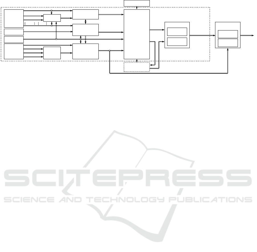
Figure 3: Structure of iRM doplar.
HMI. The HMI determines the destination and the
setting of the route guidance in relation to the de-
sired operating mode.
Communication. The communication function is
used for route guidance in order to receive mes-
sages about disturbances or warnings of wireless
communication with the environment and their
evaluation. This communication can be based on
a variety of technologies, such as V2X communi-
cation according to the WLAN standard 802.11p
or the mobile radio standard 5G.
Route Guidance. The route guidance is based on
the Dijkstra algorithm and has an interface for in-
formation from wireless communication, e.g.
about disturbances or warnings of other vehicles
(CMS level). Based on the ego position of the self-
localization, the destination input of the HMI and
the map data, an optimized route is determined ac-
cording to travel time or energy consumption.
Fleet Management. Optionally, a fleet manage-
ment can influence the route guidance of a vehicle
in order to achieve the optimum of a vehicle fleet.
Trajectory Planning. The trajectory planning de-
termines a trajectory tube from the calculated
route, considering safety and comfort aspects such
as lateral acceleration or vehicle speed.
Automated Vehicle Guidance. The automated
vehicle guidance calculates setpoints for inte-
grated vehicle dynamics control systems on the
basis of the trajectory tube as well as relevant ve-
hicle conditions such as speed or position. This
function is divided into two sub-functions for lon-
gitudinal and lateral guidance.
5 MODEL-BASED DESIGN OF
AN ANN FOR AUTOMATED
LATERAL GUIDANCE
After the interfaces and the supply of the necessary
information by the iRM doplar were introduced, in
this section, the function development from the de-
sign of the GA over the determination of the network
architecture and derivation of the fitness function up
to the validation is described.
5.1 Modelling
Linear single-track models have proven to be a good
approximation for describing the lateral dynamics of
automobiles (Schramm, 2018). The longitudinal ve-
locity v
x
of the vehicle with the mass m is assumed to
be constant. The orientation of the vehicle in the pla-
nar coordinate system is described by the yaw angle
ψ. The yaw rate ψ and the yaw acceleration ψ are
characterizing the rotational movement of the vehicle
about its vertical axis with the moment of inertia J
z
.
The slip angle β is the difference between the direc-
tion of the centre of gravity speed and the longitudinal
axis of the vehicle. The centre of gravity is defined by
the distances to the centres of the front l
F
and the rear
axle l
R
. The steering angle δ describes the angle be-
tween the front wheels and the longitudinal axle and
is the input of the linear single-track model. The steer-
ing angle is also defined as output of the ANN, since
it is required as the setpoint of a subordinate vehicle
dynamics control system. It is assumed that the sys-
tem
can set the steering angle within a computation
step, so it does not have to be simulated. The corner-
ing stiffnesses of the front and rear wheels c
αF
and c
αR
describe the constantly proportional relationship be-
tween the cornering angles of the respective axle and
,
,
,⋯
trajectory generator
kinematics
kinetics
environment
sensors
,
,
≡
,
data fusion
,
,
,
,
odometry
state sensors
self-localization
environment
perception
map data
e
stabilisation
conditions
route guidance
fleet management
HMI
communication
mapping
automated vehicle
guidance
longitudonal
guidance
lateral
guidance
ICAART 2020 - 12th International Conference on Agents and Artificial Intelligence
728

the associated lateral forces (Schramm, 2018). The
equations of motion of the linear one-track model are:
β
=‐
c
αF
+c
αR
m·v
x
β+
c
αR
·l
R
-c
αF
·l
F
m·v
x
2
-1ψ+
c
αF
m·v
x
δ
(1)
ψ
=
c
αR
·l
R
-c
αF
·l
F
J
z
β-
c
αF
·l
F
2
+c
αR
·l
R
2
J
z
·v
x
ψ+
c
αF·l
F
J
z
δ
(2)
In order to test and ensure the ANN's generaliza-
tion capability, training and testing take place on ran-
domly generated tracks. The limited validity range of
the linear single-track model with respect to lateral
acceleration a
y
must already be considered during
route generation. With the radius of curvature ρ ap-
plies to the linear single-track model:
|a
y
|=
v
x
2
ρ
≤4 m·s
-2
(3)
The guidelines for the layout of country roads is-
sued by the German Federal Highway Research Insti-
tute (BASt) specify the ratio between the length of a
straight line and the subsequent curve radius This
guideline and the minimum curve radius have been
considered during automatic track generation.
The vehicle was extended with a body whose
outer dimensions exceed those of the chassis. A vir-
tual sensor was modeled to detect the vehicle's own
position and orientation in the trajectory tube. The
sensor is centrally mounted on the front of the body
and detects the boundaries of the trajectory tube in an
angle range of ±40 ° and a radius of 8 m. The orien-
tation and position of the vehicle in relation to the the
trajectory tube is determined by eleven straight lines
with a constant angular distance. The distances be-
tween the point where the straight lines intersect with
the trajectory tube and the mounting point of the sen-
sor make up its output signal d. If a line has no inter-
section with the trajectory tube, the measured value
corresponds to its maximum range, in this case 8 m.
5.2 Design of the Genetic Algorithm
In this contribution, an individual is represented by
one ANN. The connection weights are called param-
eters or genes. In the crossing of two individuals, ran-
domly selected genes of two randomly selected indi-
viduals are swapped. When a mutation is performed,
one or more genes of a randomly selected individuals
are reinitialized. The stochastic influence neither
guarantees that the individuals of each generation will
improve nor that a global optimum will be achieved.
Therefore, a well-adjusted GA is essential.
A large population n
i
increases the genetic diver-
sity and thus the exploration of the parameter space,
but on the other hand also requires a higher computa-
tional effort per generation. Smaller populations pro-
mote evolutionary optimization whilst less explora-
tion of the search space. In tournament selection, n
t
randomly selected individuals are compared in n
i
tournaments. The best individuals evolve into the
next generation. A larger tournament size leads to a
reduction in diversity while at the same time making
better exploitation of the known parameter space. The
crossing rate describes the proportion of individuals
in the population who reproduce in pairs by recom-
bining their genes into the next generation. Whether
the modified individuals behave better or worse is not
known before. Although recombination improves ex-
ploitation, the crossing rate should not be too high to
minimize the probability of losing good individuals
of the current generation. With a small mutation rate,
the learning process tends to yield a local optimum,
while a large rate increases the probability of finding
a global optimum, but also the risk of losing good in-
dividuals. After intensive research, the GA parame-
ters for learning lateral guidance were defined:
Population Size: 50
Tournament Size: 5
Crossing Rate: 90 %
Mutation Rate: 1 %
5.3 Determination of the Network
Architecture
The definition of the ANN’s architecture includes the
determination of the topology as well as the number
of hidden layers and the neurons contained therein.
The sizes of the input and output layers can be derived
from the function structure and interfaces (Figure 2).
The eleven sensor values are the inputs of the ANN
and are mapped on the steering angle representing the
output. It can be assumed that the same lateral posi-
tion and orientation on the track always require the
same action. Therefore, no sequential signals have to
be processed, so that a feed-forward network, in par-
ticular a multilayer perceptron, can be used, which
keeps the computational and training effort low. The
hyperbolic tangent serves as the activation function.
In a preliminary test, ANNs with one, two and
three hidden layers are examined to determine a suit-
able network architecture. The number of neurons per
hidden layer n
hidden
was selected to n
hidden
={2,4,8,16}
in order to consider very small as well as large layer
sizes (Heaton, 2015). All solution candidates are
trained on the same track with a length of approx.
640 m and tested on five further identical tracks.
Artificial Neural Networks and Reinforcement Learning for Model-based Design of an Automated Vehicle Guidance System
729
To train and evaluate the various network archi-
tectures a fitness function Fit was used, in which the
distance covered by the vehicle u is rewarded. In ad-
dition, there is a bonus B when the vehicle reaches the
finish of the track. As soon as the car body touches
one of the boundaries of the trajectory tube, the sim-
ulation of this individual is classified as a crash and
aborted. The fitness function is:
Fit=u+B
(4)
B=
1000 arrived at destination
0else
(5)
The evolutionary process of a GA is infinitely
long, which is why the definition of suitable termina-
tion conditions is necessary. For the preliminary test,
the only requirement is to reach the destination. Due
to the stochastic influence of the GA, it is not guaran-
teed that an individual that meets the requirements
will evolve in finite time. Therefore, the maximum
number of generations is defined as 25.
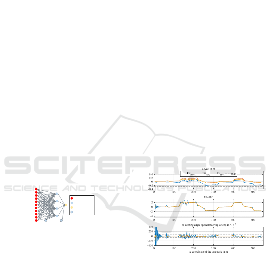
The preliminary test showed that ANNs with one
hidden layer and four neurons (Figure 4) are already
able to learn lateral guidance. Larger ANNs were only
partially able to complete the test tracks without
crashing. Using large ANNs is associated with a
higher risk for overfitting and a higher computational
effort. Therefore, it is advisable to always use the
smallest possible ANN (Figure4). This also keeps the
parameter space for optimization as small as possible.
Figure 4: ANN developed in the preliminary experiment.
5.4 Optimization of the Fitness
Function
According to subsection 4.1, the ANN should keep
the vehicle in the middle of the trajectory tube without
oscillations. In consequence the absolute value devi-
ation from the centre of the trajectory tube |Δy| is pe-
nalized. In order to avoid oscillations, steering angle
speeds |δ
|> δ
= 60 °·s
-1
on the steering wheel are pe-
nalized too. For a stable evolution process, a monot-
onously increasing fitness function is recommended
(Duriez, 2017). For this the penalized parameters |Δy|
and |δ
| must be normalized to their respective maxi-
mum values Δy
max
and δ
max
and multiplied by a factor.
The factor k
1
describes the percentage of the maxi-
mum possible penalty of the reward received. The ra-
tio between |Δy| and |δ
| is expressed by k
2
:
Fit = u+B - k
1
·u k
2
|
Δy
|
Δy
m
a
x
+
1-k
2
fδ
δ
max
(6)
fδ
=
δ
δ
>δ
ac
0else
(7)
The optimum values for k
1
and k
2
according to the
requirements have to be determined experimentally.
The new requirements result in two further termina-
tion conditions. Firstly, the root-mean-sqaure value of
the lateral deviation Δy must not exceed 25 cm over
the entire track. In addition, no inadmissible steering
angle speed may occur on the entire tracks.
During extensive simulation series it was found
out that k
1
=50 % is the best compromise between un-
acceptable driving behavior at a too small and an in-
creasing tendency for overfitting at a too high penalty.
In further experiments the factor k
2
was determined.
Figure 5 exemplarily shows the simulation results of
three fitness functions according to eq. (6) on one of
the test tracks. The indices for the different colored
curves indicate the respective value for k
2
. The lateral
deviation, the steering angle and the steering angle
speed at the steering wheel are shown over the x-co-
ordinate of the approx. 630 m long track.
Figure 5: Simulation results on one of test tracks.
Figure 5a shows that for all factors k
2
, the lateral
deviations are completely inside the dashed lines
marking the RMS boundaries, so that they all fulfil
this requirement. The blue curve with k
2
=100 % does
not take δ
into account. Therefore, Figure 5c shows
steering angle speeds exceeding the acceptable range.
The resulting strong oscillations can also be observed
in the steering angle and the lateral deviations curves.
The red curve with k
2
=50 % shows a significantly im-
proved behavior regarding the steering angle speed.
This has also led to smoother curves of the steering
angle and lateral deviation. The minimum value for
input neuron
hidden neuron
output neuron
bias neuron
ICAART 2020 - 12th International Conference on Agents and Artificial Intelligence
730
k
2
is 50 %, since a vehicle which always drives at the
edge of the lane without oscillations is dangerous. All
yellow curves with k
2
=80 % show a good compro-
mise |Δy| and |δ
|. The steering angle speed is consist-
ently within the acceptable range and barely exceeds
the values of the red line. Furthermore, there has been
an improvement in the lateral deviation. Neverthe-
less, the oscillations, especially at the beginning of
the track, could not be completely avoided. The re-
maining amplitudes in Figure 5a are in the range of
millimeters, which are retained anyway in a real ap-
plication due to imperfect environmental conditions.
With k
2
=80 %, the best result was achieved in the
simulation series, which is why this GA-trained ANN
forms the result of the model-based designed function
for automated lateral guidance.
5.5 Validation of the ANN
The training and testing of the ANN designed so far
has been carried out with a constant vehicle speed of
50 km·h
-1
, on tracks with a length of up to 800 m. In
order to extensively validate the driving function, a
longer distance had to be travelled at different but
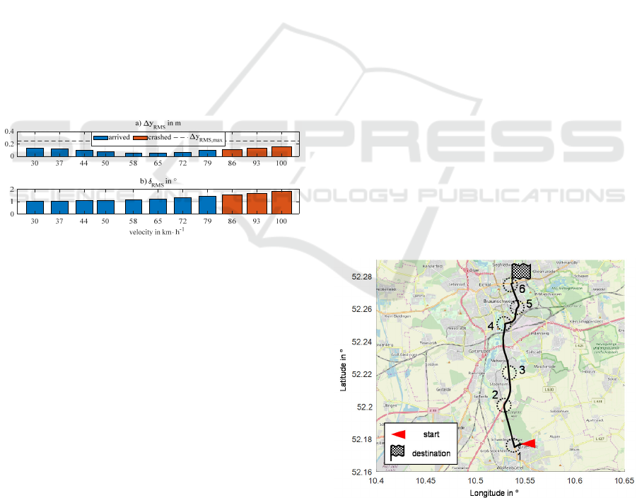
constant speeds. Figure 6 shows the simulation result.
Figure 6: Simulation results with different velocities.
It is noticeable that the vehicle caused crashes at
speeds >79 km·h
-1
and that the RMS values of the lat-
eral deviations in Figure 6a show a V-shaped course.
The ANN does not know the speed, so it always out-
puts the same steering angle for the same sensor sig-
nals. This increases the tendency to high-frequency
steering angle oscillations with large amplitudes at
higher speeds when looking at the δ
RMS
values in Fig-
ure 6b. At 65 km·h
-1
, a favorable combination of am-
plitude and frequency seems to help the vehicle keep-
ing in the middle of the trajectory tube. At lower
speeds there are no oscillations to compensate the de-
viations, so the ANN causes higher but acceptable lat-
eral deviations. However, the driving function has po-
tential for improvement, especially at higher speeds.
From these simulation results it can be concluded
that the model-based developed and GA-trained ANN
is able to realize automated lateral guidance for the
speed range between 30 and approx. 70 km·h
-1
with
constant speeds according to the requirements.
6 VERIFICATION AND
OPTIMAZATION
To verify and further optimize the ANN for auto-
mated lateral guidance, it will be tested in a pilot ap-
plication under more realistic conditions. The vehicle
should automatically navigate from Ostfalia in Wolf-
enbuettel (Salzdahlumer Straße 46/48) to the Institute
of Automotive Engineering (IfF) at the Technical
University of Braunschweig (Hans-Sommer-Straße
4) as shown in Figure 7. In an offline simulation, ad-
ditional functions of the iRM doplar on AMS level
are used for route guidance and trajectory planning.
At first, the vehicle must localize itself and calcu-
late a route. The black line in Figure 7 shows the re-
sulting travel time-optimized 12.8 km long route.
Since this is an offline simulation, no dynamic infor-
mation from the V2X communication were consid-
ered. The trajectory generator then calculates a trajec-
tory tube considering safety and comfort aspects. The
sensor model uses this information to determine the
position and orientation of the ego vehicle and passes
it to the ANN. Since this can only operate at constant
speeds so far, it is set to 50 km·h
-1
over the entire route
because of the inner-city sections. When navigating
on the route, curved sections are particularly chal-
lenging. The five most critical situations as well as an
exemplary straight line are marked by the numbered
circles in Figure 7 and will be evaluated exemplarily.
Figure 7: Pilot Application with time optimized route.
Figure 8a and b show simulation results in seg-
ments of the sections 2 and 5 from Figure 7. In Figure
8a and b the trajectory tube is drawn in black and its
Artificial Neural Networks and Reinforcement Learning for Model-based Design of an Automated Vehicle Guidance System
731
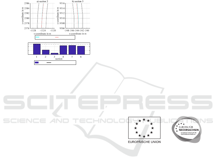
centre line in turquoise, while the actual travelled
route was drawn in red. Here it can be seen that the
trajectory tube contains relatively strong kinks in
some places due to a large discretization. At the kinks
the vehicle deviates quite strongly from the set course
but maintains a realistic and more pleasant route.
Shortly before and after the kinks, the vehicle holds
the middle of the trajectory tube very exactly.
Figure 8: Exemplary results of the pilot application.
Figure 8c shows the maximum lateral deviations
of the vehicle from the centre of the trajectory tube in
the respective sections. The dashed line marks the ac-
ceptable limit during training (Δy
RMS
=25 cm). Except
for the first section of the route with a particularly
small, i.e. difficult, curve, this limit was adhered to
over the entire track. For segments 2 and 5, these de-
viations are about 12 and 23 cm at the kink points
drawn, and thus within a very good range. On the
straight section 3 the maximum lateral deviation is
less than 4 cm. Within the 3.5 m wide trajectory tube,
a maximum lateral deviation of 85 cm is possible for
the simulated vehicle with a width of 1.81 m.
Thus, both parts of the iRM doplar and the func-
tion for automated lateral guidance have proven to be
functional in a realistic pilot application. Considering
the constraints that the vehicle drives at a constant
speed, the function is verified. By extending the func-
tionality regarding the longitudinal dynamics, the sys-
tem can be further optimized in the future.
7 CONCLUSION AND
FUTURE WORK
This paper shows the model-based design of a func-
tion for automated lateral guidance using ANNs and
GAs. After a short presentation of the the motivation
and the underlying methodology of this work, the ba-
sics of automated lateral guidance as well as ANNs
and RL were explained. Subsequently, requirements
and a functional structure for the driving function
were derived from the problems of today's ADAS and
the advantages of ANNs and GAs were pointed out.
This was followed by a description of the model-
based design process of the ANN for automated lat-
eral guidance. After the training on a remarkably
short distance with a length of 640 m, the function for
automated lateral guidance was validated. Finally, the
function was verified in a realistic pilot application
and optimization potential regarding the longitudinal
dynamic behavior was pointed out.
A future work step is to extend the functionality
of the lateral guidance function for operation at higher
and variable speeds. A further step is the analogous
design of an ANN for longitudinal guidance respec-
tively their integration for planar vehicle guidance.
ACKNOWLEDGEMENTS
This publication resulted from the subproject "au-
toEMV" (Holistic Electronic Vehicle Management
for Autonomous Electric Vehicles) in the context of
the research project "autoMoVe" (Dynamically Con-
figurable Vehicle Concepts for a Use-specific Auton-
omous Driving) funded by the European Fund for Re-
gional Development (EFRE | ZW 6-85030889) and
managed by the project-management agency Nbank.
REFERENCES
Bartels, A. et al., 2015. Querfuehrungsassistenz. In Hand-
buch Fahrerassistenzsysteme, Springer Fachmedien,
Wiesbaden, Germany, pp. 937-957
Duriez, T., Brunton, S., Noack B. R., 2017. Machine Learn-
ing Control. Springer International Publishing, Cham,
Switzerland
Eraqi, H. E., Eldin, Y. E., Moustafa, M. N., 2016. Reactive
Collision Avoidance using Evolutionary Neural Net-
works. 8th International Conference on Evolutionary
Computation Theory and Applications, Porto, Portugal
Heaton, J., 2015. Artificial Intelligence for Humans, vol. 3,
CreateSpace Independent Publishing Platform
Koelbl, C., 2011, Darstellung und Potentialuntersuchung
eines integrierten Quer- und Längsreglers zur Fahr-
zeugführung. Ph.D. Thesis,.Technical University of
Munich, Munich, Germany
c) lateral deviation in cm
center line
traveled route
value
termination condition
0
0.1
0.2
0.3
ICAART 2020 - 12th International Conference on Agents and Artificial Intelligence
732

Scherler, S. et al., 2019. iREX 4.0 – A contribution to a pre-
dictive, energy-optimal drive of Autonomous Electric
Vehicles equipped with Range Extender by means of
Cross-linking and Digitization. Hybrid and Electric Ve-
hicles, Brunswick, Germany
Schramm, D., Hiller, M., Bardini, R., 2018. Vehicle Dy-
namics, Springer, Berlin, Heidelberg, Germany
Semrau, M., 2017. A validated Simulation framework for
testing ADAS in Chinese traffic situations. Wolfsburg,
Germany
Such, F. P., Madhavan, V. Conti, E., Lehman, J., Stanley,
K. O., Clune, J., 2017. Deep Neuroevolution: Genetic
Algorithms Are a Competitive Alternative for Training
Deep Neural Networks for Reinforcement Learning.
CoRR
Vishnukumar, H. J. et al., 2017. Machine learning and deep
neural network — Artificial intelligence core for lab
and real-world test and validation for ADAS and auton-
omous vehicles: AI for efficient and quality test and
validation.2017 Intelligent Systems Conference (Intel-
liSys), London, pp. 714-721
Zang, J. et al., 2018. Traffic Lane Detection using Fully
Convolutional Neural Network. 2018 Asia-Pacific Sig-
nal and Information Processing Association Annual
Summit and Conference (APSIPA ASC), Honolulu, HI,
USA, pp. 305-311
Artificial Neural Networks and Reinforcement Learning for Model-based Design of an Automated Vehicle Guidance System
733
