
The Seamless Low-cost Development Platform LoRra for Model
based Systems Engineering
Sven Jacobitz and Xiaobo Liu-Henke
Ostfalia University of Applied Sciences, Salzdahlumer Str. 46/48, 38302 Wolfenbüttel, Germany
Keywords: Rapid Control Prototyping, Systems Engineering, Code Generation, Real-time Interface, Measurement and
Calibration, Low-cost, Scilab, Battery Management.
Abstract: This paper presents a seamless low-cost Rapid Control Prototyping (RCP) development platform, LoRra for
short, based on the open source software Scilab / Xcos. The model-based, verification-oriented RCP devel-
opment process is introduced to master the increasing system complexity in ever-shortening development
cycles. Within this process Model-in-the-loop (MiL)-, Software-in-the-Loop (SiL)-, and Hardware-in-the-
Loop (HiL)-simulations are performed for testing and optimization. Based on requirements derived from the
process, the concept of the LoRra platform is developed first. It contains model libraries, a code generator, a
real-time interface, real-time hardware and a human-machine interface for measurement and calibration tasks.
Subsequently, the design of each component will be discussed. Finally, a first validation and optimization of
the platform is carried out by using the state of charge estimation for lithium-ion batteries.
1 INTRODUCTION
Nowadays, a key challenge for innovative companies
is to develop even more complex products faster and
faster. In order to meet the constantly intensifying re-
quirements, more and more hard- and software is being
integrated in technical systems. Core of the resulting
embedded mechatronic systems are the embedded con-
trol units (ECU) with implemented intelligent func-
tions for signal processing and control. Due to the rap-
idly increasing amount of functionality as well as the
degree of networking, increasingly complex software
components are designed which interact strongly with
each other (Quantmeyer, 2013). As a result, software
and hardware designs often contain numerous errors
that need to be detected through intensive testing and
eliminated in time-consuming iteration loops. How-
ever, in order to meet the demand for a fast time to mar-
ket, the development and validation of embedded
mechatronic systems using an effective development
methodology is indispensable (Liu-Henke, 2005).
For this reason, the structured, model-based, veri-
fication-oriented Rapid Control Prototyping (RCP)
development process is used, which includes system
structuring and composition. Model-in-the-Loop
(MiL)-, Software-in-the-Loop (SiL)-, and Hardware-
in-the-Loop (HiL)-Simulations are carried out for
testing. In the automotive industry, this has estab-
lished itself in the development of ECUs (Staron,
2017). The methodology is characterized by the high
degree of consistency and automation, from model-
ling, model-based function design and automated
generation of source code to the automated imple-
mentation on real-time hardware. All process steps
mentioned are seamlessly executed in a fully auto-
mated CAE environment to minimize manual work
and resulting random errors. Currently, only cost-in-
tensive combinations of CAE tools and real-time
hardware, such as Matlab/Simulink with a dSPACE
system, support the development process described
above in a seamless way (Liu-Henke, 2014).
As part of the EU-funded research project Low-
Cost Rapid Control Prototyping System with Open
Source Platform for the Function Development of
Embedded Mechatronic Systems (LoCoRCP), the
seamless Low-Cost RCP-Development Platform,
LoRra for short, is being developed at Ostfalia. The
following paper presents the concept and design of
the integrated RCP platform. It will be applied for the
functional development of a battery management sys-
tem for verification and optimization.
The rest of the paper is structured as follows. Sec-
tion 2 describes the basic RCP-methodology, which
is provided by the platform. Afterwards, in section 3
Jacobitz, S. and Liu-Henke, X.
The Seamless Low-cost Development Platform LoRra for Model based Systems Engineering.
DOI: 10.5220/0008993500570064
In Proceedings of the 8th International Conference on Model-Driven Engineering and Software Development (MODELSWARD 2020), pages 57-64
ISBN: 978-989-758-400-8; ISSN: 2184-4348
Copyright
c
2022 by SCITEPRESS – Science and Technology Publications, Lda. All rights reserved
57
the concept of the platform is introduced. The follow-
ing section 4 describes the design of each module of
the LoRra platform. For a first verification and opti-
mization, section 5 demonstrates the application of an
Extended Kalman Filter for State of Charge estima-
tion for Lithium-Ion batteries as part of a battery man-
agement system (BMS). The paper closes with a con-
clusion and a short outlook in section 6.
2 METHODOLOGY
As mentioned in the introduction, modern embedded
mechatronic systems are developed and validated us-
ing model-based, verification-oriented RCP method-
ology. After system structuring through modulariza-
tion and hierarchization, integration takes place by
using the mechatronic composition. Based on the
specifications and requirements, a model of the real
plant is created and analysed. This model serves as
the basis for functional synthesis. Using offline sim-
ulations, the designed algorithms are tested and opti-
mized (MiL). Once a sufficient state of functionality
has been reached, the automated generation of code
takes place, which in turn is tested and optimized in
offline simulations (SiL). With increasing software
quality, HiL-simulations are carried out. For this pur-
pose, the designed function is automatically inte-
grated into a real-time environment, compiled into an
executable program and transferred to target hard-
ware. Further tests and optimizations take place under
real-time conditions before the final implementation
and validation on the real system is done (Liu-Henke,
2005).
The presented RCP methodology is seamlessly
supported by an integrated computer aided engineer-
ing (CAE) development environment. For this pur-
pose, libraries for modelling are required. The analy-
sis and functional synthesis is supported by using
block diagrams. A code generator, transforms the
model into C code and then the function is automati-
cally implemented on a target hardware using a real-
time interface (RTI). Due to the high degree of auto-
mation and the model-based validation in early
phases of development, errors are systematically min-
imized.
3 CONCEPTION
The following section discusses the concept of the
LoRra platform to support the methodology outlined
in Section 2. First, the issues to be solved are concre-
tized by the problem description. From these, the con-
cept of the platform is derived.
3.1 Problem Description
As early as the mid-1990s tools for the integrated
model-based development of mechatronic systems
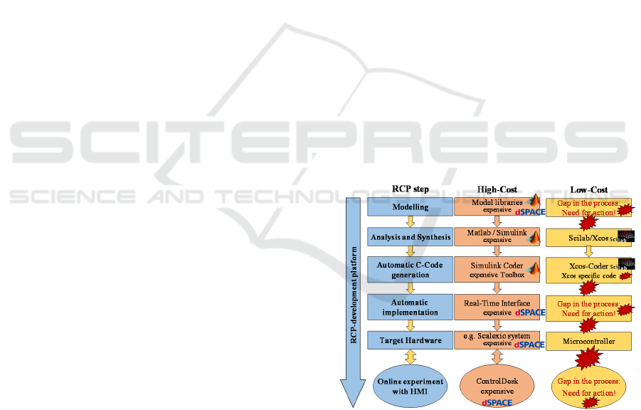
were published (Hanselmann, 1996). The combina-
tion of the CAE tool Matlab / Simulink with real-time
systems from dSPACE (see Figure 1 on the left) has
established itself as a quasi-standard in the automo-
tive industry (Beine, 2009).
A wide range of libraries are available from this
high-cost platform to support modelling and analysis
as well as functional synthesis. The Simulink Coder
supports the automated transformation of block dia-
grams into source code in a variety of ways as well as
for various target languages and systems. dSPACE's
RTI links the Simulink model to the interfaces of a
real-time hardware and automatically implements the
generated executable on a target hardware. Here, a
wide range of powerful real-time systems are availa-
ble. The program ControlDesk provides a human-ma-
chine interface (HMI) for interactive communication
in case of measurement and calibration tasks
(Schuette, 2005). The process sequence in combina-
tion with the described tool chain illustrated by the
middle of Figure 1.
Figure 1: High-Cost RCP process and principle Low-Cost
solution.
The costs associated with the purchase and opera-
tion of the presented tool chain are immense (Liu-
Henke, 2014). For this reason, various open-source
solutions with comparable functionalities have been
developed. Especially the CAE environment Scilab
with its graphical simulation tool Xcos (formerly Sci-
MODELSWARD 2020 - 8th International Conference on Model-Driven Engineering and Software Development
58
cos) comply with many functions of Matlab / Sim-
ulink (Jacobitz, 2018). In combination with a micro-
controller as real-time hardware, a low-cost develop-
ment process could be realized. However, there are
still various gaps in this process as shown by Figure
1. Single process steps, such as code generation, can
be realized up to a limited extent, but there is still a
lack of automation and consistency.
The simulation of dynamic systems with Xcos and
the generation of C code to accelerate the simulation
is described in detail by (Campbell, 2010). Already at
the beginning of the 2000s, approaches arose which
execute this generated code on a PC using the real-
time Linux system RTAI (Bucher, 2005), (Duma,
2009) and couple it to a real process via the interface
library COMEDI (Weichinger, 2011). Work that is
more recent deals with the execution of the program,
generated by Xcos, on a microcontroller (Skiba,
2015). Also the code itself has been improved. Thus,
(Grabmair, 2014) presented a toolbox that generates
C code for a microcontroller from specially imple-
mented Xcos blocks. Furthermore, the automated par-
allelization of the generated source code is being re-
searched (Reder, 2017).
Many of the above solutions are based on old ver-
sions of Scilab and are not under development any-
more. In addition, many partial solutions are available,
but the integration to a seamless process according to
Figure 1 is missing. For the current Scilab version 6,
the solutions presented are not compatible.
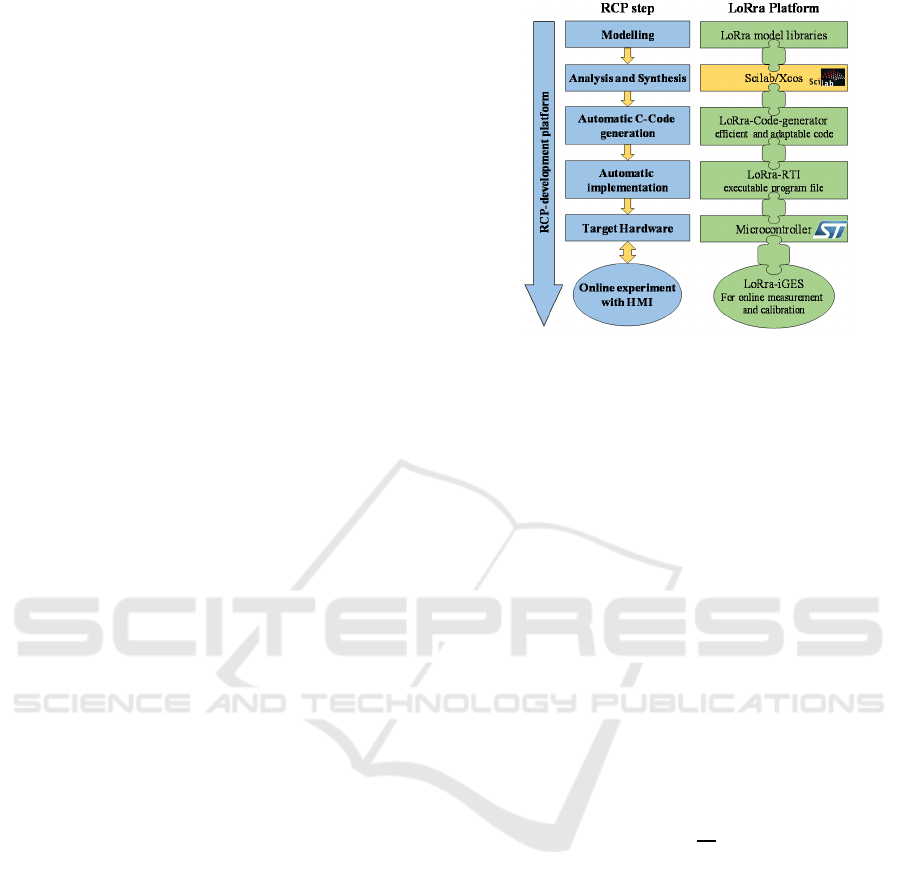
3.2 Conception of LoRra
In order to fill the gaps described in Section 3.1 and
meet the non-functional requirements, the functionality
is modularized, first. The LoRra model libraries are
used to support modelling in Xcos. The automatic gen-
eration of C code is performed by the LoRra-Code-
generator. Further processing for online simulation on
a microcontroller is possible with the LoRra-RTI. Fi-
nally, online experiments can be performed using the
LoRra-iGES graphical user interface. All mentioned
modules are integrated to fill the gaps shown in Figure
1 and build the seamless LoRra platform. Figure 2
summarizes the over-all concept of LoRra.
4 TOOL DESIGN
The following section describes in detail the design
of the modules introduced in section 3. As they are
essential, the focus will be on the LoRra Model librar-
ies, the LoRra-Code-generator, the LoRra-RTI and
the target hardware.
Figure 2: Concept of the LoRra-Platform.
4.1 Design of the LoRra Model
Libraries
The LoRra platform supports a large number of dif-
ferent technical domains as model libraries. In this
section, the modeling of a lithium-ion battery cell ac-
cording to (Quantmeyer, 2014a) is carried out in an
exemplary manner. This model will be used for the
application in section 5.
The behaviour of the lithium-ion battery depends
highly nonlinear on the current
as well as on the
state of charge (), temperature and the state of
health (). For this model, the influences of and
are neglected.
First, the is determined on basis of the bal-
ance equation (Eq. 1). The determined charge is
scaled with the nominal capacity
and the coulomb
efficiency
.
dt
(1)
The terminal voltage
is calculated from an
equivalent circuit model (cf. Figure 3). It consists of
a voltage source representing the open circuit voltage
(), a series resistance and four RC modules to ap-
proximate the dynamics. The as well as the pa-
rameters of resistors and capacitors depends highly
nonlinear on the . This nonlinearity poses a huge
challenge particularly to the identification.
Therefore, identification is done by using a elec-
trical impedance spectroscopy in the frequency do-
main at various SoC level. After that, the model has
been validated in time domain using a dynamic stress
test (DST).
The Seamless Low-cost Development Platform LoRra for Model based Systems Engineering
59
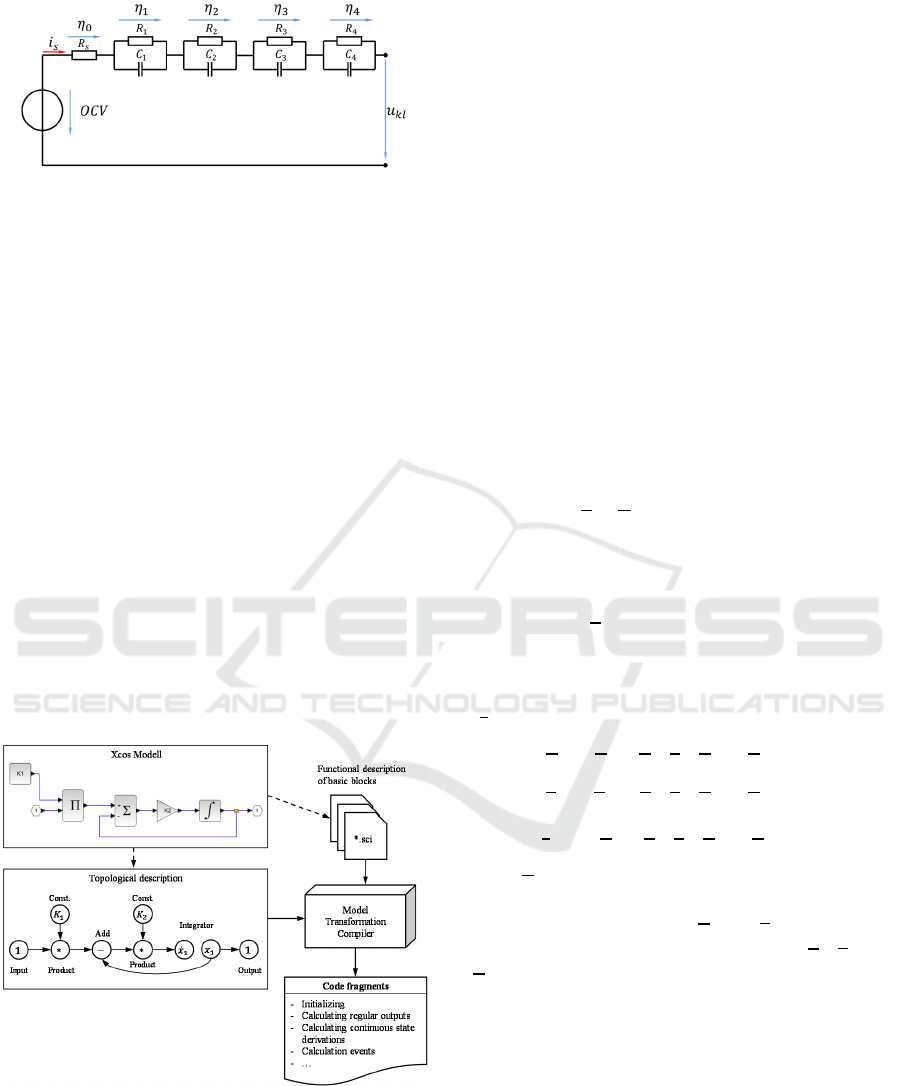
Figure 3: Equivalent circuit model of a battery
(Quantmeyer, 2014a).
4.2 Design of LoRra-Code-generator
As shown in section 2, the automated generation of
code from the model is an essential part of the RCP
process. The block diagram of the function is trans-
formed into equivalent, high-performance C code
without user intervention. This avoids random errors
caused by manual programming and saves develop-
ment time (Hanselmann, 1996).
Figure 4 illustrates the concept of the LoRra-
Code-generator. The Xcos model is divided into its
functional and topological description. The functional
description is available for each basic block in the
form of its algorithms. The topology, i.e. the connec-
tion of the blocks to the model logic, can be inter-
preted as a directed graph. A model transformation
compiler links both information to code fragments e.g.
for initialization, output and state calculation and
event calculation. These can be optimally used for
post-processing (e.g. for generating SiL- or HiL-sim-
ulations).
Figure 4: Concept of the LoRra-Code-generator.
4.2.1 Topological Description of the Model
As mentioned before, the topology of the Xcos model
is represented by a graph
,,
. is the set
of nodes (each node represents a block in the dia-
gram), is the set of regular edges (continuous sig-
nals) and is the set of event edges (time discrete
event impulses).
A node
∈ can represent a basic block or a hi-
erarchy element. Hierarchy elements are called Super
Blocks and contain an independent dataflow graph.
The basic blocks Input and Output are used to link it
to the next higher level. Since the sequence of input
or output signals of a block is relevant for the calcu-
lation, an edge
∈ or
∈ must also contain in-
formation about the input / output port number in ad-
dition to the source and target nodes.
4.2.2 Functional Description of the Blocks
The functional behavior of each basic block can be
described as an extended nonlinear state space repre-
sentation:
,
,
,
,
(2)
,
,
,
,
(3)
Where is the current simulation time,
the vector
of continuous states, the vector of time-discrete
states,
the vector of input variables,
the parame-
ter vector and
the vector of output variables. Both,
the continuous and the time-discrete states can jump
when the block is activated by an event input. In ad-
dition, then the time of each output event impulse
(
) is calculated (Nikoukhah, 1996):
,
,
,
,
,
(4)
,
,
,
,
,
(5)
,
,
,
,
,
(6)
Here,
is the event input vector. It contains both the
external event inputs of the block and internal events
(e.g. due to zero crossing).
and
are the values
of the states right after event activation.
,
and
are the states / inputs at the arrival of an event.
4.2.3 Model Transformation Compiler
The Model transformation compiler is the core of the
code generator and drives the process. This is done in
three steps:
- Pre-processing of the Xcos model
- Linking of functional and topological description
- Post-processing of the generated code fragments
During pre-processing, the Xcos data structure is first
transformed into the dataflow graph (cf. section 4.1.1).
MODELSWARD 2020 - 8th International Conference on Model-Driven Engineering and Software Development
60

It is then checked for validity. In particular, this con-
cerns the inclusion of unsupported basic blocks or al-
gebraic loops. To recognize algebraic loops, a modi-
fied depth-first search is performed to find cycles in
the dataflow graph. If the given model is considered
to be valid, the topology can be optimized, e.g. by re-
moving paths that are not used or by merging similar
structures into functional groups. Finally, starting
from each source node, a topological sorting of the
graph is performed to determine the correct calcula-
tion sequence.
To link topology and functional description, the
given algorithms for each node
∈ are trans-
formed into C code by executing formal transfor-
mation rules. Taking into account the previously de-
termined calculation sequence, the code fragments
are thus joined up. This can be done for the model as
a whole (without considering hierarchy levels) or by
encapsulating functions while retaining the hierar-
chical structure. The post-processing of the generated
code is mainly done by associated modules (e.g. to
generate a SiL- or HiL-simulation).
4.3 Design of the LoRra-RTI
The RTI implements the model from the offline sim-
ulation automatically into a real-time environment for
HiL-simulations as described in section 2. The func-
tionality can be divided into two tasks. Firstly, the
Xcos model must be linked to the interfaces of the
target hardware (e.g. digital out, A/D converter,
PWM generation, etc.). This takes place on model
level in Xcos. In addition, the automated implemen-
tation of the model on the real-time hardware must be
realized.
4.3.1 Model to Hardware Interfaces
For linking the model with the hardware interfaces,
specially implemented Xcos basic blocks are used.
By the deposited functional description, correspond-
ing code for reading, scaling and processing of signals
is generated. Due to the modular concept of the code
generator, the peripheral interfaces or microcontroller
functions can easily be implemented in Xcos as a new
basic block.
Presently just a limited number of interfaces is
supported. Due to the modular, functional descrip-
tion, an extension will be easily possible. The config-
uration of the interfaces (like ports and frequencies)
is read from an XML file at runtime of the RTI and
can therefore be adapted without altering the RTI
blocks.
4.3.2 Implementation of the Model
In order to implement an Xcos model on real-time
hardware, the process illustrated by Figure 5 has to be
executed. The code fragments, generated by the code
generator, are assembled to the application software
by using code-templates and finally linked with a
basic software by the embedded code transformer.
The basic software includes, e.g., the real-time oper-
ating system (RTOS) and the hardware abstraction
layer. It is a component of the RTI and needs to be
adapted in view of the specific target hardware. In ad-
dition to optimize the generated source code, the Em-
bedded Code Transformer configures the RTOS, in-
tegrates memory-protection mechanisms, and effects
linking to driver- and function libraries. Use of a lay-
ered architecture having standardized interfaces ena-
bles flexible adaption to different microcontrollers as
real-time hardware.
Figure 5: Process for translating and programming by the
LoRra-RTI (Jacobitz, 2019).
Compiler and linker calls are completely auto-
mated. Subsequently, the generated executable pro-
gram file can be analysed in view of extracting, e.g.,
memory map information. These will be saved and
transmitted to the iGES interface for measurement
and calibration.
4.3.3 Structure of the Real-time
Environment
The real-time environment is structured in layers with
standardized interfaces. It contains the layers basic
and application software. Figure 6 illustrates the sim-
plified structure of the resulting software system.
The application software consists of hardware-in-
dependent components of the RTI (e.g. the XCP
server for processing commands for measurement
and calibration tasks) and one or more user-generated
Xcos
model
LoRra code generator
Start
End
code
templates and
basic software
LoRra embedded
code transformer
source
code
code
fragments
compiler and linker
programmer interface
executable
binaries
The Seamless Low-cost Development Platform LoRra for Model based Systems Engineering
61
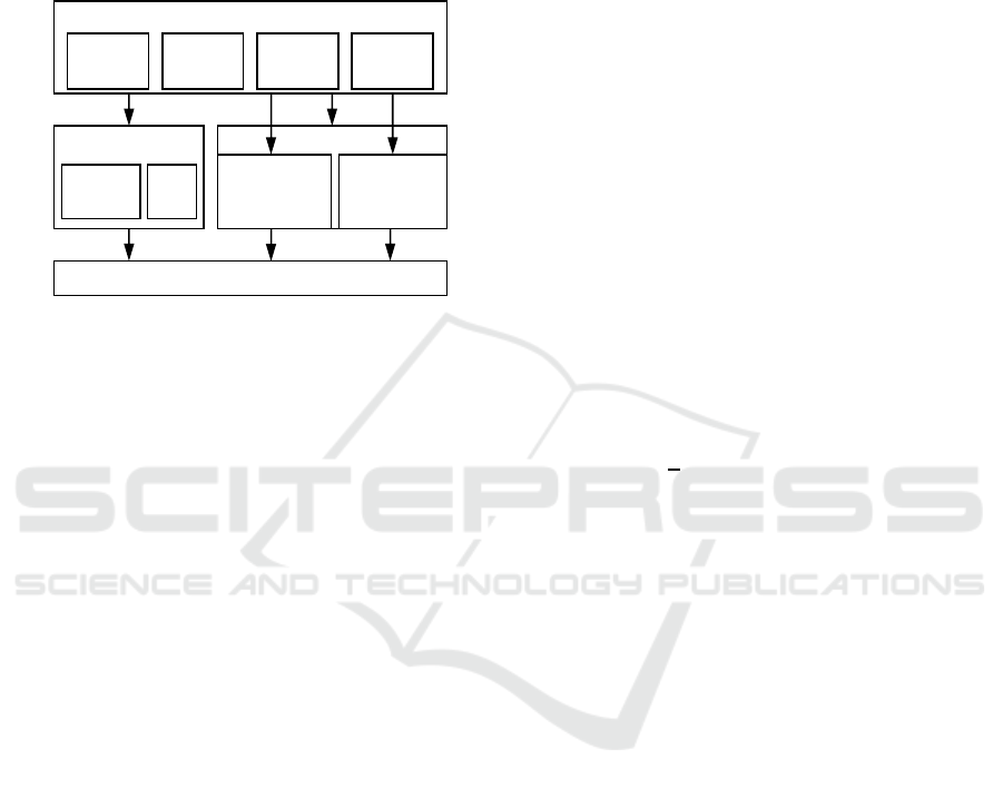
applications. Usually, these applications are encapsu-
lated modules that do not share resources. If two ap-
plications use the same resource (e.g. memory or pe-
ripherals), access is controlled by memory protection
functions of the operating system such as mutex.
However, particular care must be taken here to ensure
that no deadlocks occur (e.g. by path coverage tests).
Figure 6: Software structure of the real-time environment.
The access to the basic software as well as the mi-
crocontroller takes place via standardized interfaces.
The CMSIS API standard allows the usage of multi-
tasking, memory protection and so on independently
of the specifically implemented RTOS. In addition to
the operating system, the basic software also includes
functions for simplified hardware access (Hardware
Abstraction Layer, HAL) and more complex drivers
such as a TCP/IP stack.
5 APPLICATION OF LoRra
For the verification, optimization and demonstration
of the LoRra platform, the seamless functional design
of a State of Charge (SoC) estimator as part of a bat-
tery management system (BMS) for LiFePO
4
cells
will be performed in this section. The design process
is carried out according to the methodology presented
in Section 2. First, the concept of the BMS is intro-
duced. After that, the modelling and synthesis is done
using the LoRra model libraries. Finally, the results
of MiL-, SiL- and HiL-simulations are discussed.
5.1 BMS
The battery system is a typical embedded control sys-
tem containing four LiFePO
4
batteries connected in
series, sensors, actuators and an information-pro-
cessing unit. The BMS consists of a central battery
management controller, which is used for high-order
algorithms such as SoC estimation, power prediction
or a safety concept, and decentralized cell modules on
each battery cell. The cell modules provide as well
acquisition of the terminal voltage and communica-
tion via CAN to the control unit as the local execution
of the load balancing.
An essential function of the BMS is the SoC esti-
mation. Since many other functions depend on the es-
timated SoC, only minor deviations of maximum
±1% may occur during operation (long-term behav-
iour). A further challenge is the determination of the
unknown SoC during initialization of the BMS (con-
vergence behaviour). The estimated SoC must reach
a stationary value within a short time (maximum 5s).
5.2 Modelling and Synthesis
To design the SoC estimator using the LoRra plat-
form, a sufficiently accurate model of the battery pack
is needed. The LoRra model library offers among oth-
ers the nonlinear battery model, introduced in section
4.1, which has already been identified and verified.
An Extended Kalman Filter (EKF) according to
(Quantmeyer, 2014b) is used for SoC-estimation be-
cause of the nonlinear system behaviour. Therefore
the battery model is transformed into state-space with
the state vector
, consisting of the SoC and the over
voltages at the RC-elements (
), the current
as in-
put and the terminal voltage
as output.
The algorithm of the EKF consists of a correction
and a prediction step. First, the states predicted by the
last time step are corrected, using measurement data
and the error covariance. Then the states and error co-
variance for the next step are predicted by using the in-
puts. The filter is initialized at the correction step with
initial values for the states and the error covariance.
The covariance matrix of the measurement is
determined using various measurements on the real
system with help of the LoRra-iGES and a subsequent
analysis of the noise. Finally, the covariance matrix
of the system
was selected as a weighting matrix
with a compromise being made between stability of
the EKF and sufficiently fast convergence according
to (Liu-Henke, 2017).
5.3 MiL- / SiL-simulation
The designed EKF is now tested and optimized by
various offline simulations (MiL) in the LoRra plat-
form. For the tests, the battery starts with 99 %
and the EKF is initialized with = 80 % to test as
well the convergence as the stationary behaviour. Af-
ter a brief idling period the battery pack is subjected
to the dynamic stress test as already used for validat-
ing the battery model.
CMSIS-Driver
Microcontroller
Complex
drivers
Hardware
Abstraction
Layer
CMSIS-Wrapper
RTOS …
application software
XCP
Server
Appli-
cation 1
Appli-
cation 2
…
basic software
MODELSWARD 2020 - 8th International Conference on Model-Driven Engineering and Software Development
62
After a sufficient quality has been achieved, code
is generated from the EKF model using the LoRra-
Code-generator. The generated code is then further
tested and optimized using SiL-simulations in the
LoRra test environment.
5.4 HiL-simulation
After successful SiL-simulations, the EKF is inte-
grated into the real-time environment by the LoRra-
RTI, in order to perform HiL-simulations. For the
online-simulations, a special HiL-test-rig is used. It
measures the terminal voltage as well as the current,
using an AD-converter. The cell modules are con-
nected via CAN. A safety circuit is actuated by digital
outputs. In addition, an electronic load- / source mod-
ule is driven via CAN.
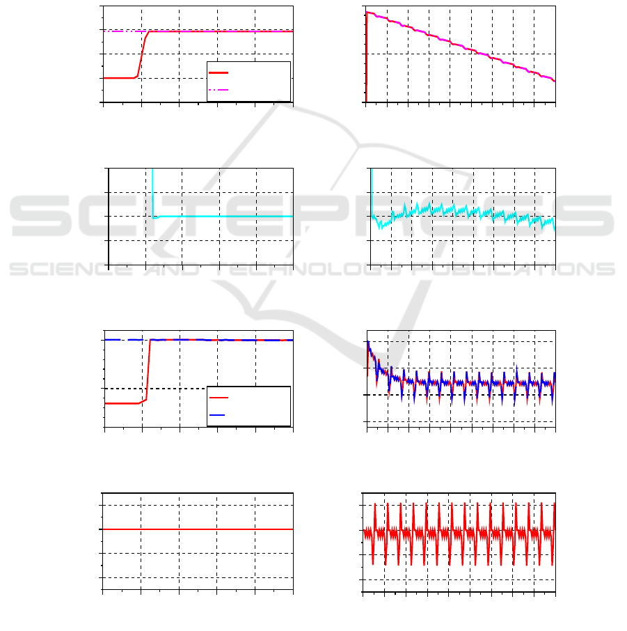
Figure 7 shows the measurement results, recorded
by LoRra-iGES. The diagram shows the SoC, the de-
viation between estimated and calculated SoC, the
terminal voltage, and the current profile. In the left
part you see clearly the rapid convergence of the fil-
ter. After that, the right part shows that the deviation
of the estimation is very small. Also, the measured
and estimated terminal voltages matches with high
accuracy.
Figure 7: Measurement results from the HiL-simulation.
024135
100
80
70
90
110
time in s
SoC in %
024135
0
-0.1
0.1
-0.05
0.05
time in s
deviation in %
024135
14
13.5
time in s
voltage in V
024135
0
-20
-10
10
time in s
current in A
02040608010 30 50 70 90
90
100
95
time in min
SoC in %
02040608010 30 50 70 90
0
-0.1
0.1
-0.05
0.05
time in min
deviation in %
02040608010 30 50 70 90
14
13
12.5
13.5
time in min
voltage in V
02040608010 30 50 70 90
0
-20
-10
10
time in min
current in A
measurement
calculation
measurement
estimation
The Seamless Low-cost Development Platform LoRra for Model based Systems Engineering
63

6 CONCLUSION AND OUTLOOK
In this paper, a seamless and integrated low-cost rapid
control prototyping development platform (LoRra for
short) based on the open source software Scilab was
presented. The model-based, verification-oriented
RCP development process, starting with the LoRra
model libraries, the automated generation of code with
the LoRra-Code-generator and its implementation on a
microcontroller as real-time hardware using the LoRra-
RTI, can thus be performed highly automated in a sin-
gle low-cost software environment. The three process
steps Model-in-the-Loop, Software-in-the-Loop and
Hardware-in-the-Loop are supported for testing and
verification.
Further work deals with the implementation of a
graphical user interface for measurement and calibra-
tion tasks. In addition, the development of a test field
for interconnected autonomous guided vehicles for
further verification is being forced. For this purpose,
it is planned to add functions from the IoT, Industry
4.0 and Smart Home areas to the LoRra-RTI.
ACKNOWLEDGEMENT
The results presented were obtained in the context of
the project LoCoRCP that is funded by the EFRE
Fund of the European Union (grant number ZW 6-
85003460). Responsibility for the con-tent of this pa-
per lies with the authors.
REFERENCES
Beine, M., Eisemann, U., Fleischer, D., Stamatov, S., 2009.
Key factors for successful integration of automatic code
generation in series production development. In SAE
2009 World Congress & Exhibition.
Bucher, R., Balemi, S., 2005. Scilab/Scicos and Linux
RTAI - a unified approach. In Proceedings of the 2005
IEEE Conference on Control Applications.
Campbell, S. L., Chancelier, J.-P., Nikoukhah, R., 2010. Mod-
eling and Simulation in Scilab/Scicos with ScicosLab 4.4.
Springer Science+Business Media. New York
Duma, R., Dobra, P., Trusca, M., 2009. Rapid Control Pro-
totyping educational toolbox for Scilab/Scicos. In Pro-
ceedings of European Control Conference 2009.
Grabmair, G., Mayr, S., Hochwallner, M., Aigner, M.,
2014. Model based control design - A free tool-chain.
In Proceedings of European Control Conference 2014.
Hanselmann, H., 1996. Automotive control: from concept
to experiment to product. In Proceedings of the Joint
Conference on Control Applications Intelligent Control
and Computer Aided Control System Design.
Jacobitz, S., Liu-Henke, X., 2019. A Real-Time Interface
for Xcos – Demonstrated on a Battery-management
System. In Scilab Conference 2019.
Jacobitz, S., Scherler, S., Liu-Henke, X., 2018. Model-
based design of a scalable battery management system
by using a low-cost Rapid Control Prototyping System.
In Proceedings of Thirteenth International Conference
on Ecological Vehicles and Renewable Energies.
Liu-Henke, X., Duym, S., 2005. Model-based functional
validation of the interconnected mechatronic vehicle
(original: Modellgestützte Funktionsabsicherung des
vernetzten mechatronischen Kraftfahrzeugs). In Pro-
ceedings of VDI Mechatronik 2005.
Liu-Henke, X., Feind, R., Roch, R., Quantmeyer, F., 2014.
Investigation of low-cost open-source platforms for de-
veloping of mechatronic functions with rapid control
prototyping. In 10th International Conference on
Mechatronic Systems and Materials.
Liu-Henke, X., Scherler, S., Jacobitz, S., 2017. Verification
oriented development of a scalable battery management
system for lithium-ion batteries. In Proceedings of
Twelfth International Conference on Ecological Vehi-
cles and Renewable Energies.
Nikoukhah, R., Steer, S., 1996. SCICOS - a dynamic sys-
tem builder and simulator. In Proceedings of the IEEE
International Symposium on Computer-Aided Control
System Design.
Quantmeyer, F., Liu-Henke, X., 2013. Hardware in the
Loop Test Rig for Development of Control Algorithms
for Electric Vehicles. In Solid State Phenomena, 198,
507-512.
Quantmeyer, F., Liu-Henke, X., 2014a. Modeling the Elec-
trical Behavior of Lithium-Ion Batteries for Electric Ve-
hicles. In Solid State Phenomena, 214, 40-47.
Quantmeyer, F., Liu-Henke, X., 2014b. State of Charge Es-
timation for Lithium-ion batteries in Electric Vehicles
using Extended Kalman Filtering. In 1st International
Symposium on Energy Challenges & Mechanics.
Reder, S., 2017. The ARGO Approach: Parallelization
Toolchain for Model-based Real Time Applications. In
Proceedings of the 12th HiPEAC conference.
Schuette, F., Berneck, D., Eckmann, M., Kakizaki, S.,
2005. Advances in Rapid Control Prototyping. In SAE
2005 World Congress & Exhibition.
Skiba, G., 2015. Utilizing Scilab and Xcos for real-time con-
trol and measurement applications. In ScilabTEC 2015.
Staron, M., 2017. Automotive Software Architectures.
Springer International Publishing. Cham.
Weichinger, K., 2011. A Nonlinear Model-Based Control
realized with an Open Framework for Educational Pur-
poses. In Proceedings from the 13th Real-Time Linux
Workshop.
MODELSWARD 2020 - 8th International Conference on Model-Driven Engineering and Software Development
64
