Labelling of Continuous Dynamic Interactions with the Environment
using a Dynamic Model Representation
Juan C. Ramirez and Darius Burschka
Machine Vision and Perception Group of Faculty of Informatics, Technische Universit
¨
at M
¨
unchen,
Boltzmannstr 3, Garching bei Munchen, Germany
Keywords:
Motion Analysis, Action Labeling, Task Characterization, Action Description, Task Prediction.
Abstract:
We propose an extension for a dynamic 3D model that allows a hieratchical labeling of continuous interactions
in scenes. While most systems focus on labels for pure transportation tasks, we show how Atlas information
attached to objects identified in the scene can be used to label not only transportation tasks but also physical
interactions, like writing, erasing a board, tightning a screw etc. We analyse the dynamic motion observed
by a camera system at different abtraction levels ranging from simple motion primitives, over single physical
actions to complete processes. The associated observation time horizons range from single turning motion
on the screws tightened during a task over the process of inserting screws to the entire process of building
a device. The complexity and the time horizon for possible predictions about actions in the scene increase
with the abstraction level. We present the extension at the example of typical tasks observed by a camera, like
writing and erasing a whiteboard.
1 INTRODUCTION
Complex environments expose multiple parallel ac-
tions happening in different parts of the scene. The
agents acting in the scene try to model the dynamic
changes, which allows them to predict the future
changes and reduces the required frequency in which
the action needs to be verified. Depending on the level
of the abstraction, the prediction horizon may vary
from a few seconds for primitive motion trajectories,
over multiple seconds for basic actions, like screw
tightening, all the way to multiple minutes in case that
the system can recognize the current process being ex-
ecuted in some part of the environment. A dynamic
model as the one presented in (Ramirez and Burschka,
2013) provides different abstraction modalities and
a-priori descriptors that can be used by dynamically
configurable plugins, like navigation, object recogni-
tion, action labeling modules, etc. The action labeling
presented in (Chen and Burschka, 2018) characterized
pure transportation actions that were segmented by
changes in the contact relation between the manipu-
lator and the object in the scene. This plugin uses ge-
ometric Localtion Areas stored in the geometric part
of the hybrid model (Fig.1). The current extension
utilizes a segment of the observed motion trajectory
associated with dynamic objects (blobs) in the model
to represent interactions with the physical strucutres
Observed
2/3D Scene
Dynamic 3D Model
Agents
Navigation/Transportation
Action Labeling
Object Recognition
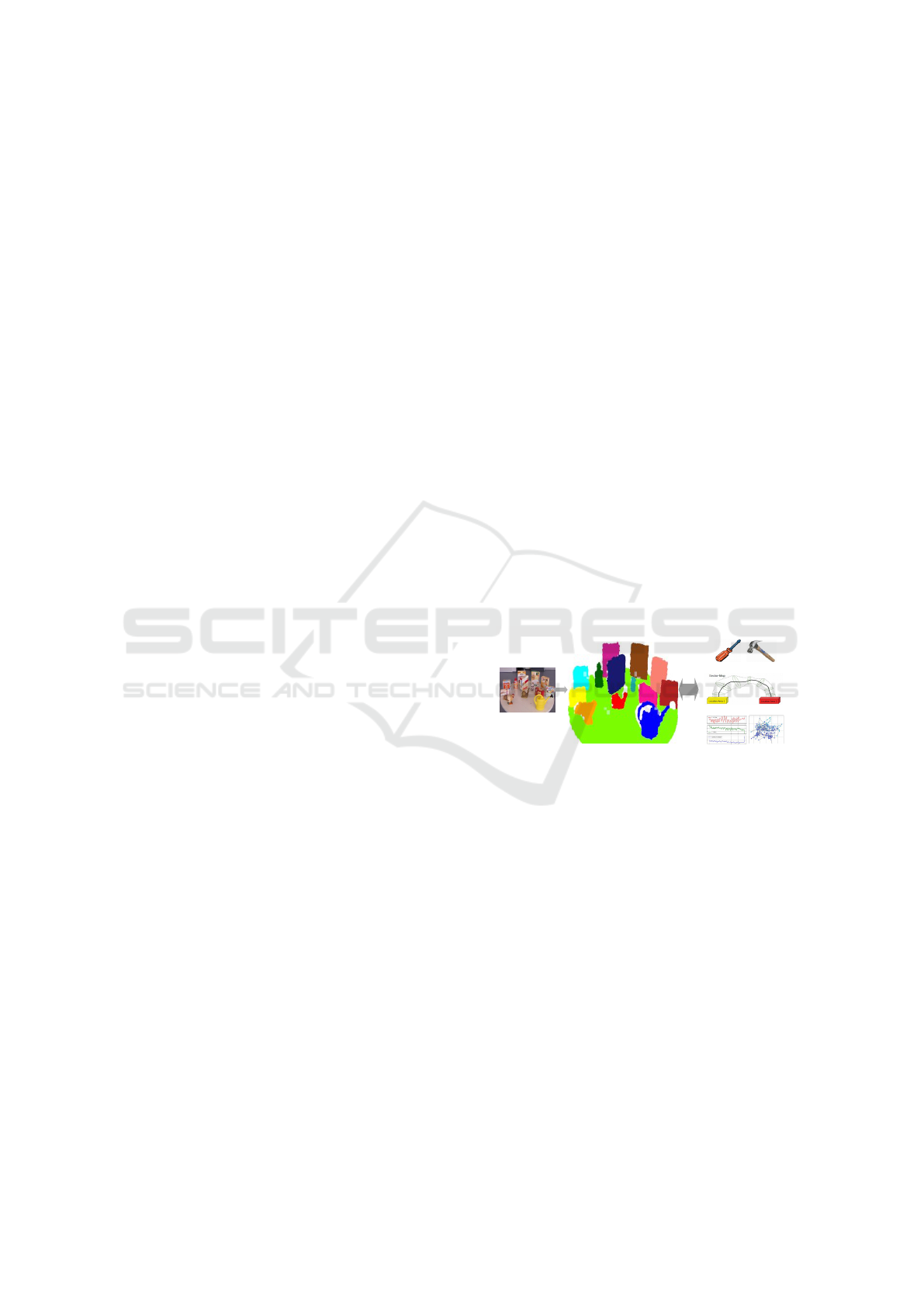
Figure 1: Different abstraction modalities, agents, acting
on a dynamic 3D model. The model offers geometric seg-
mented structures, blobs, as potential object candidates.
The agents, in turn, analize different aspects and function-
alities of the given blobs. The action labeling agent is the
main topic in this work.
in the scene at different abstraction layers. Analo-
gous to a typical visual prediction-correction tracking
scheme, in which a dynamic model is required to give
hints about the expected behavior of the state of the
target, a set of data providing information about hu-
man actions is also required to describe and disam-
biguate certain tasks from others. The results of the
analysis described in this paper provide a set of mo-
tion patterns for this purpose. We take into considera-
tion three main elements. The first aspect, commonly
overlooked in the visual identification or recognition
of human actions or activities, is to observe the mod-
ifications or alterations that such actions might pro-
voke in the immediate surroundings. For example,
794
Ramirez, J. and Burschka, D.
Labelling of Continuous Dynamic Interactions with the Environment using a Dynamic Model Representation.
DOI: 10.5220/0008986407940800
In Proceedings of the 15th International Joint Conference on Computer Vision, Imaging and Computer Graphics Theory and Applications (VISIGRAPP 2020) - Volume 4: VISAPP, pages
794-800
ISBN: 978-989-758-402-2; ISSN: 2184-4321
Copyright
c
2022 by SCITEPRESS – Science and Technology Publications, Lda. All rights reserved

(a) (b) (c) (d) (e)
(f) (g) (h) (i) (j)
Figure 2: Two introductory examples representing two different levels of prediction horizons. In the top row the child starts
walking (a) but he does not follow the predicted path (red line) (b), the child modifies his path (c), a last fitted trajectory (red
line) to the actual observed path (cyan points) is fitted (d). In the bottom row some words are written on a whiteboard (f,g)
and the motions motions of the hand are projected online onto the surface constraint (h) and PCA-enclosed (i). In both scenes
the plane constraint is estimated: the green floor and the wall in (a,f) and the motions are projected onto these planes: cyan
spots in (b,d) and black lines and points in (h). (e) shows the child’s projected path with its curvature values, in (j) projected
motion for the whiteboard example are shown.
by chopping, we could observe the state of the onion
or potato before the action, and confirm the slices of
onion or the stripes of potato afterwards. A second
element to consider is to know what object is in used.
With this we will be able to narrow a bunch of ac-
tions down to a small set of tasks that are specifically
related with the object. Since an object can have dif-
ferent functions the next direct element to examine
would be to observe how it is handled. Considering
that a task or action is linked to the use of one sin-
gle object and that an activity comprises a series of
tasks involving several objects, in this work we fo-
cus on the analysis of single tasks by integrating and
associating the above mentioned elements: what ob-
ject is in used, how it is handled and how it interacts
with the environment. However, instead of observing
the changes of the environment after a task execution,
which might be a challenge by its own, we simplify
and generalize this stage by combining the last two
elements in our approach: we project the path of the
executed motions onto the constraining surface near-
est to the action. The reasons for this: i) in many in-
door environments specific actions and activities oc-
cur close to or over supporting surfaces, e.g., table,
desk, stove, workbench, wall, sink, etc.; ii) having a
plane constraint as reference the distance from it to
the action motions can be decoupled from the orig-
inal motion measurement, this distance is in general
constant or presents small variations. The advantages
obtained with this are: i) the 3D motion path is re-
duced in one dimension leaving a 2D projected mo-
tion track as the action’s fingerprint on the plane, ii)
as explained in the paper, a semantic tracking, i.e.,
the prediction and monitoring of tasks can be per-
formed by decomposing the projected 2D pattern into
its primitive motion components.
Prediction Horizons. In fig.2 we show two exem-
plary scenarios that show two different levels of ab-
straction in the predcition of actions. The first scene
on the top row shows a child walking from the left to
receive an offered object on the right (a), under a low
level prediction scheme (red straight line) the child’s
walking can be estimated with the up-to-this-time ob-
served positions (cyan path) (b), the child’s actual mo-
tion does not follow the predicted path since he un-
expectedly turns back (c), in the end a straight path
could still be fitted to the entire observed path (d) al-
though it would not expose the actual behavior. In this
short prediction horizon the expected child’s behavior
is confirmed only during the first seconds. A higher
level predictor agent might take into consideration un-
expected but possible changes in the child’s state, e.g.,
by observing the curvature in his trajectory (e) labels
like walking, stoping, turning, etc. can be assigned.
In the bottom row a scene corresponding to writing
on a whiteboard is shown (f,g), the motions of the ac-
tive actor, the hand, are observed (tracked) and pro-
jected onto the surface constraint, the whiteboard (h),
and they are encapsulated by PCA (Principal Compo-
nent Analysis) for further processing (i), the projected
motions on the board are shown in (j). A long-term
Labelling of Continuous Dynamic Interactions with the Environment using a Dynamic Model Representation
795

prediction agent might combine these elements (ob-
ject, motion, interaction) and tag them as: writing on
a board. Depending on the abstraction level some-
times it is more convenient and beneficial to observe
closer and more attentive some motion features rather
than others. In the child example it is more advan-
tageous to keep track on how his actual position de-
viates from the predicted path at each step, whereas
in the whiteboard example it might be more helpful
to examine either the final written pattern e.g., by an
OCR (Optical Character Recognition) system or the
motion patterns projected onto the plane, in order to
determine the action in progress, writting vs erasing.
We organize the paper as follows. In the next
section we describe briefly some other published ap-
proaches to the visual recognition of actions or activ-
ities. In Sect. 3 the theorical and mathematical fun-
dations as well as the image processing procedures of
the approach are explained. We run some experiments
in different scenes with different objects/tools, the re-
sults are presented in Sect.4. In Sect. 5 we give some
final comments and remarks on the presented work.
2 RELATED WORK
It is not uncommon to find very frequently in this
line of research the words: activity, task, action, and
atomic action. In this context we define the follow-
ing concepts. Atomic action: or stroke or gesture,
generally they describe fast, short, instantaneous and
continuous motion displacements, e.g., a hand twist,
lifting an arm, etc; Action: or task, it is composed
by an ordered sequence of atomic actions, e.g., drink-
ing, writing, etc; Normally one action is associated
with one object. Activity: is a series of different ac-
tions that are shared in space and time, e.g., cook-
ing, driving, etc. One activity is associated with mul-
tiple objects. There exist also cases in which these
concepts overlap, for example, eating as an activity
or action, turning the steering wheel as an action or
atomic action. The literature in this area spans from
the recognition of atomic actions to the identifica-
tion of activities in a general, global perspective, this
is, such actions and activities are not linked to an
specific object. Here we describe some representa-
tive examples. In (Ju Sun et al., 2009) they tackled
the problem of action recognition in video sequences
scenes by introducing three levels of context, a point-
level context with a SIFT descriptor (Lowe, 2004),
an intra-trajectory context defined by the trajectory of
the salient SIFT features and an inter-trajectory con-
text where the intra-trajectory is related to the other
objects in the scene. The approach in (Kuehne et al.,
2012) combines histograms of sparse feature flow
with hidden Markov Model HMM for action recog-
nition. Global histograms of sparse feature flow are
built for each input image and processed for recog-
nition of small action units by the HMM stage, then
the actions units are combined into a meaningful se-
quence for the recognition of the overall task. Re-
cently in (Chen and Burschka, 2018) in order to pre-
dict and label human actions with objects they pro-
posed a graphical representation to link the objects
with their corresponding usual places inside a scene.
In this representation they decouple the action regions
inside the environment into location areas (LA) and
Sector Maps (SM). The former is where actually the
action occurs and the latter indicates rather the trans-
portation way between LAs. Following this approach
we can say that our work focus on the LAs, since
we observe mainly how an object interacts in order
to characterize its functionality.
3 APPROACH
Inside our analysis framework we can identify the
next main functional blocks: hand tracking, plane de-
tection and point projection to a plane. In Algo.1 we
present an overview of the workflow of the approach.
Algorithm 1: Main Workflow of the Approach.
Result: Projected Motions and Motion
Pattern
1 GET I
3d
(k); /* rgb-3d image */
2 DETECT-PLANE;
3 SEG-3D hand; /* 3D segmentation */
4 init KF
3d
; /* kalman filter */
5 while I
3d
(k) 6=
/
0 do
6 DETECT-PLANE;
7 KF
3d
.predict hand-pos;
8 SEG-3D hand-pos;
9 KF
3d
.correct hand-pos;
10 PROJECT-Hand-centroid;
11 end
12 run-PCAon( proj-pts );
13 get Motion-Patterns;
3.1 Hand Tracking and Plane Detection
We assume we know a-priori the object in used. For
this an additional object recognition block can be
added to the system or it can be simply introduced
manually. In any case we track the motions of the
hand rather than the object’s for several reasons: i) the
hand is the active actor in the visual environment that
VISAPP 2020 - 15th International Conference on Computer Vision Theory and Applications
796

generates the motions, ii) once the hand is grasping
an object its 3D geometry does not change abruptly,
which makes it simpler to track, as a blob, without any
need of a 3D model, iii) the hand covers partially or
almost totally the object it grasps, or the object is not
visible for the sensory system, like some objects in
our experiments: pen, knife, fork, eraser, screwdriver.
In this work we are not interested in hand gestures,
either, hence, our tracking model of the hand is a seg-
mented blob of 3D points corresponding to its visible
surface. The implemented a Kalman filter (Welch and
Bishop, 1995)(Kalman, 1960) tracks the trajectoty of
3D segmented hand’s centroid. To determine the con-
straining plane we mark three points inside the visual
2D scene. The normal-point form of the plane is de-
fined by the Eq. 1 and the potential 3D plane points
are chosen with a fixed distance threshold. See Fig.3.
ax + by + cz + d = 0 (1)
where a,b and c are the constants defining the normal
vector to the plane
ˆ
n = [a, b, c], and d is the distance
from the origin of the coordinate system to a reference
point on the plane d = −
ˆ
n · p.
Figure 3: The blob segmentation of the hand is highlighted
during the tracking. The detected plane (in green with blue
normal vector) during writting on the whiteboard, tighting
with a screwdriver and during drinking are also shown. The
tracked blob centroids are shown in green.
3.2 Projection onto Plane Constraint
In order to obtain the action’s fingerprint drawn on
the plane we project each tracked hand’s centroid onto
the plane by determining the 3D vector parallel to the
plane normal that connects the current observed cen-
troid to the plane, see Fig.4. According to (Schnei-
der and Eberly, 2003) the mathematical expression
to project a point onto a plane is given by Eq.2, and
the distance from the current centroid to the plane by
Eq.3.
q’ = q − (q ·
ˆ
n + d)
ˆ
n (2)
where k
ˆ
nk = 1, q is the current hand’s centroid and
q’ is its projection onto the plane.
r =
q ·
~
n + d
k
~
nk
(3)
Figure 4: For the chinese writting style on the whiteboard,
shown in the right picture, the 3D hand’s centroids (the
green points) are projected onto the plane (black points on
the orange background). The red line represents the vector
parallel to the plane normal projecting the current centroid
onto the plane.
being r the perpendicular distance from the plane to
the current hand’s centroid. In the last step we encap-
sulate the projected pattern on the plane by running
the Principal Components Analysis (PCA) (Bishop,
2006).
4 EXPERIMENTS
The application code was implemented in c++ pro-
gramming language running in an ASUS i7 laptop
with a Nvidia GeForce 940mx card. The footages are
playbacked at the same rate they were recorded. The
plane detection as well as the motion reprojection are
performed in real time. An overview of the presented
recorded scenes is shown in Table.1.
Table 1: Characteristics of the motions and projected pat-
terns.
Object Action Projected Motion Projected Pattern
Whiteboard
writting Periodic Structured
erasing Erratic Arbitary
Screwdriver
tighting Oscillatory Centralized
pocking Sharp, Jerky Asymmetric
Hammer
hitting Sharp, Period-ish Centralized
pulling Erratic Longer in one axis
knife chopping Periodic, Oscillatory Ellipt-ish
Pen writting Periodic Structured
Fork eating Period-ish Ellipt-ish
Glass drinking Period-ish Ellipt-ish
Writting and Erasing on Whiteboard. In both ac-
tions the grasped object is in general partially cov-
ered by the hand what makes it almost completely
unperceptible for the sensory system. The projected
motions on the plane exhibit different patterns as can
be seen in Fig.5 for the writting and erasing action.
Althouhg no pattern can be observed from the pro-
Labelling of Continuous Dynamic Interactions with the Environment using a Dynamic Model Representation
797
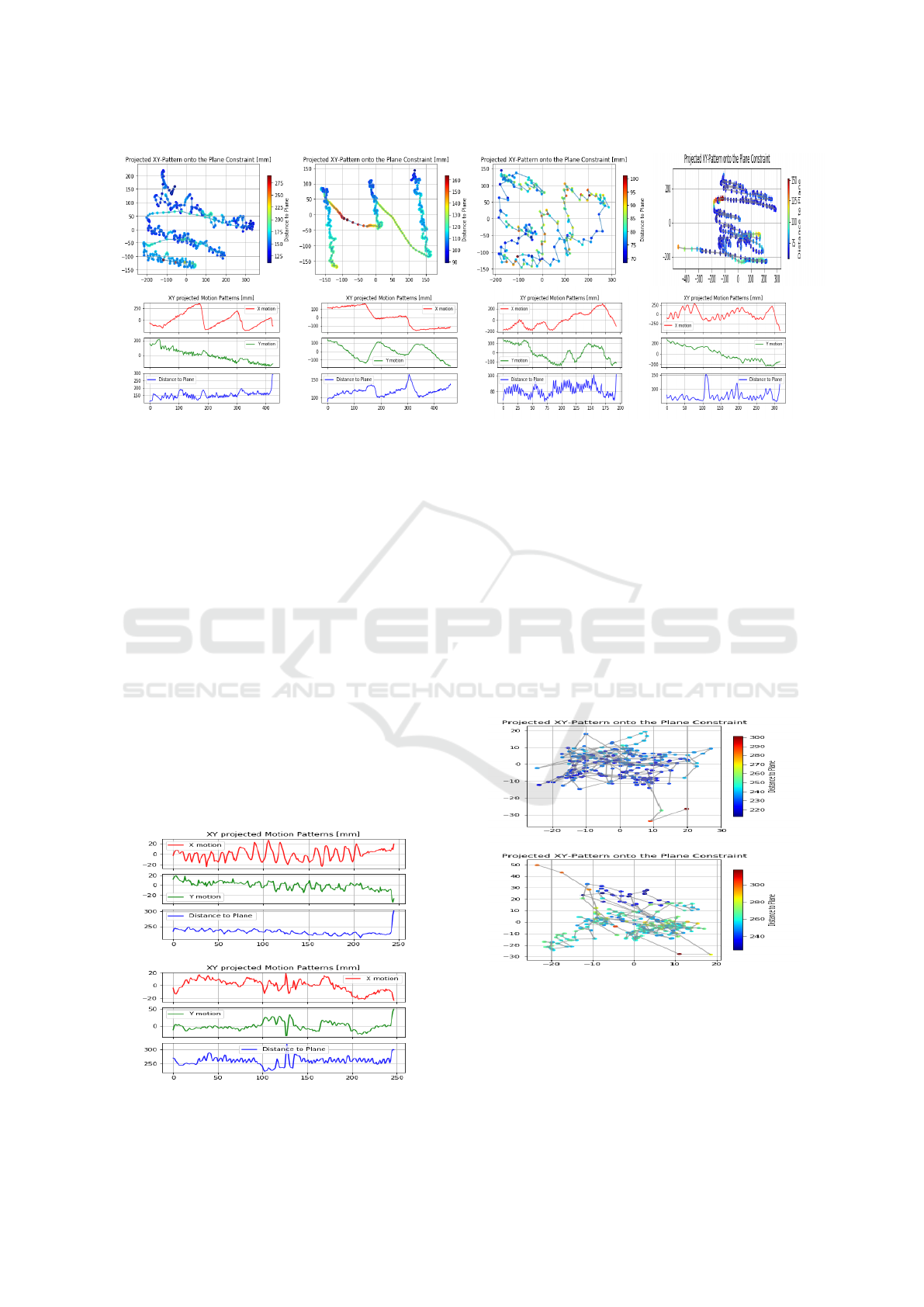
Figure 5: Whiteboard. Projected patterns on the top row, and their projected motions on the bottom row. The first column
shows the results for the occidental writing style with left-to-right horizontal writting progress and up-to-bottom row sequence,
the second column corresponds to the oriental style with up-to-down writing progress and rigth-to-left column sequence. The
last two columns correspond to two erasing sequences.
jected motion strokes corresponding to the erasing
task, since this is a rather arbitrary, disorganized ac-
tion, we can observe that the writting action gen-
erates a very structured pattern depending on the
writing style: with a constant increasing slope from
left to right corresponding to the motion along the
rows or with a decreasing slope corresponding to the
downward motion along the columns, both present-
ing small variations in the other axis that mirrors the
height or width of the written characteres. Addition-
ally, we also observe that during erasing the hand re-
mains most of time close to the whiteboard, whereas
the writting presents more separations periods.
Tighting and Poking with a Screwdriver. In Fig.6
it can be observed the irregular oscilations during the
tighting. The oscilations are more perceptible in one
Figure 6: Screwdriver. Projected motions for tighting (top)
and poking (bottom).
projected axis than the other, this could be caused by
the fact the that motions represent the positions of the
hand’s centroid which varies irregularly not only due
to its translation and rotation motions but also depend-
ing on how much of its surface is visible to the cam-
era at each frame. Instead of this erratic oscilations
the poking action presents small sharper patterns due
to the sudden hand strokes characteristic of the pok-
ing motion. In Fig.7 can be also observed that the
projected pattern of the tighting action is rather sym-
metricly sparse with a constant distance to the plane.
Figure 7: Screwdriver. Projected patterns for tighting (top)
and poking (bottom).
Hitting and Pulling with a Hammer. The spiky
plots in the three dimensions in Fig.8 give immedi-
ately the idea of an action with sudden, sharply mo-
tion strokes, which correspond to the act of hitting
with a hammer. In constrast, pulling with a hammer’s
VISAPP 2020 - 15th International Conference on Computer Vision Theory and Applications
798
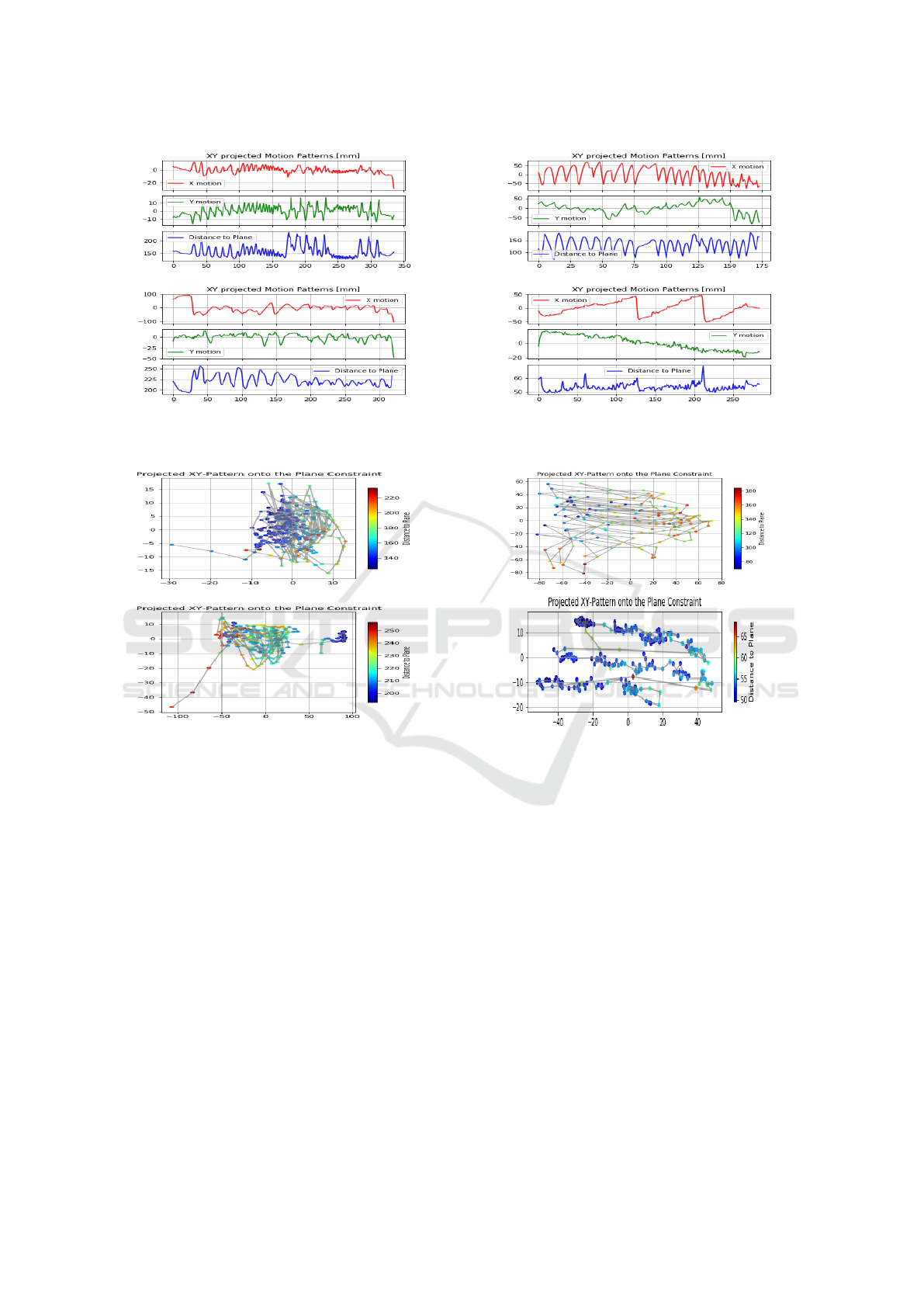
Figure 8: Hammer. Projected motions for hitting (top) and
pulling (bottom).
Figure 9: Hammer. Projected patterns for hitting (top) and
pulling (bottom).
claw presents irregular motion patterns but quite cen-
tralized and with more span in one direction due to
the swinging motion of pulling the hammer’s handle
back and forth, see Fig.9.
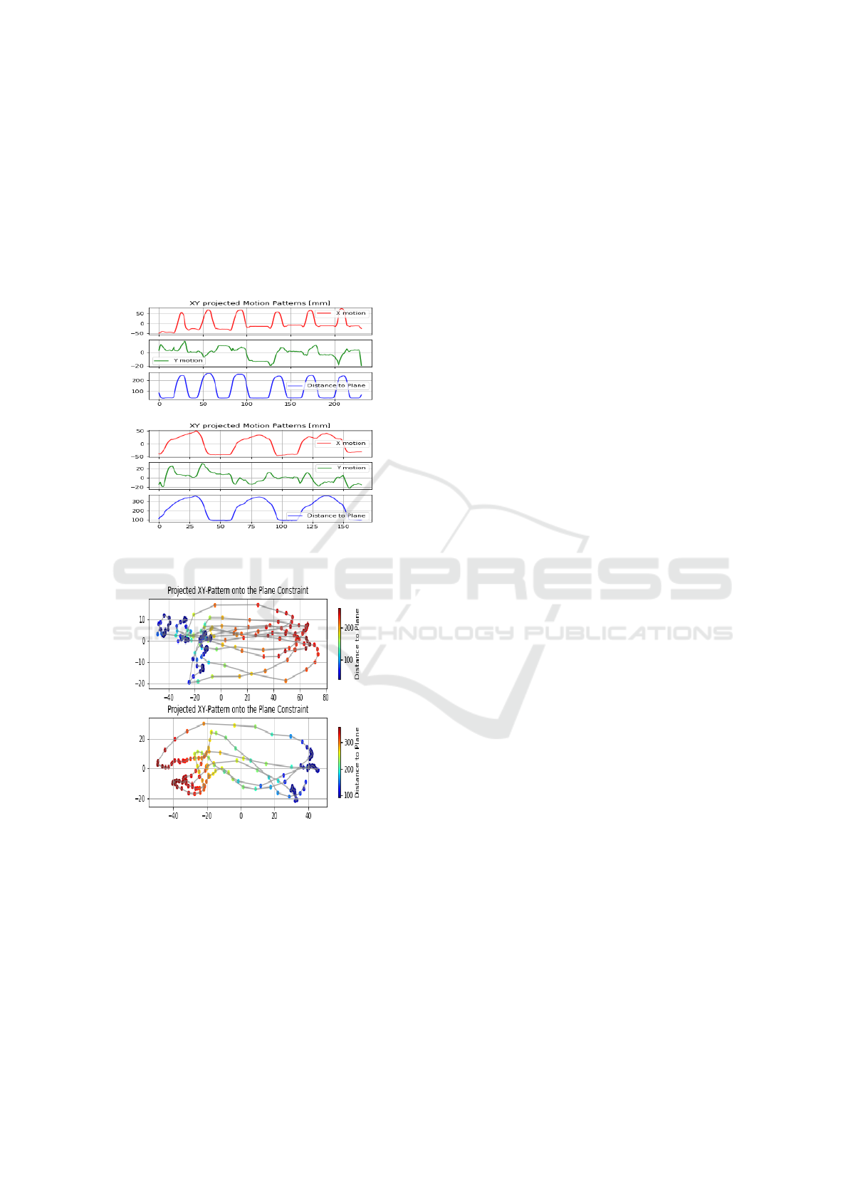
Chopping with a Knife and Writing with a Pen
over a Table. The almost regular oscilations in one
of the projected axis, x-axis in this case, and in the dis-
tance to the plane, see Fig.10, indicates that a circular-
ish pattern is drawn in a plane perpendicular to the
supporting chopping surface. This pattern indicates
the rhythm and main cutting direction, whereas the y-
axis indicates the hand’s centroid location along the
chopped object. Opposed to this oscilation pattern
the act of writting over a table presents the same very
well defined and structured motion pattern as writting
on the whiteboard. The constant slope motion in the
x-axis indicates the writting progress along the rows
with those sharp drops indicating the changes of rows.
Figure 10: Chopping vs Writting over a table. Projected
motions for chopping (top) and writting (bottom).
Figure 11: Chopping vs Writting over a table. Projected
patterns for chopping (top) and writting (bottom).
The small jerking on the y-axis indicates the draw-
ing and height of the characteres. The bias presented
in the y-axis going down might be related to the no-
perfect alignment between the PCA-axes and the row
lines during the writting, as shown in Fig.11.
Eating with a Fork and Drinking with a Glass on
a Table. If we were to observe and compare the
mimics of both actions without any object in the hand
we will find that both actions are quite identical and,
as shown in Fig. 13, they also present similar finger-
prints. The visual atomic actions with which we can
probably take them apart migth be in the way the hand
would grasp the object (fork/glass) and the backward
motion of the person’s head by drinking in constrast
to the slightly forward motion during eating. Athough
we do not observe these features in our approach,
what we do observe are: i) the frequency in wich the
hand moves back and forth from the table to the per-
Labelling of Continuous Dynamic Interactions with the Environment using a Dynamic Model Representation
799
son’s head, which is faster during eating, ii) the time
the hand stays close to the head is larger during drink-
ing, which occurs during phase when the glass is close
the mouth and it can be observed in the flatter wave
crests in the distance-to-plane plot for drinking, iii)
the head motion forwards for eating and backwards
for drinking can be perceived in the hand’s distance
to the plane in the plots, which is higher during drink-
ing, see Fig.12
Figure 12: Eating vs Drinking on a table. Projected motions
for eating (top) and drinking (bottom).
Figure 13: Eating vs Drinkig on a table. Projected patterns
for eating (top) and drinking (bottom).
5 CONCLUSIONS
In this work we presented an analysis framework that
allows us to extract the distinctive motion features that
charaterize and help to identify an action or task in
progress. This analysis mechanism, applied as an ex-
ternal agent, is fed with the segmented structures from
a dynamic 3D environment model to analyse their
dynamic properties and the interaction among them.
The agent profits not only from the extracted set of
decomposed motion primitives but also from their ar-
rangement and interactions with the environment to
boost the short-term prediction horizon from a geo-
metric level to higher level of motion understanding:
action labelling. The mext step in this work is to im-
prove the action labeling agent by giving it more au-
tonomy in the process e.g., hand, object detection, etc.
and integrating more required functional blocks with
objective to analyse more complex tasks and activities
in different scenarios.
REFERENCES
Bishop, C. M. (2006). Pattern Recognition and Ma-
chine Learning (Information Science and Statistics).
Springer-Verlag, Berlin, Heidelberg.
Chen, E. and Burschka, D. (2018). Object-centric ap-
proach to prediction and labeling of manipulation
tasks. pages 6931–6938.
Ju Sun, Xiao Wu, Shuicheng Yan, Cheong, L., Chua, T., and
Jintao Li (2009). Hierarchical spatio-temporal context
modeling for action recognition. In 2009 IEEE Con-
ference on Computer Vision and Pattern Recognition,
pages 2004–2011.
Kalman, R. E. (1960). A new approach to linear filtering
and prediction problems. Transactions of the ASME–
Journal of Basic Engineering, 82(Series D):35–45.
Kuehne, H., Gehrig, D., Schultz, T., and Stiefelhagen, R.
(2012). On-line action recognition from sparse feature
flow. In VISAPP.
Lowe, D. G. (2004). Distinctive image features from scale-
invariant keypoints. Int. J. Comput. Vision, 60(2):91–
110.
Ramirez, J. and Burschka, D. (2013). Dynamic 3d map-
ping - visual estimation of independent motions for
3d structures in dynamic environments. volume 2.
Schneider, P. and Eberly, D. H. (2003). Geometric Tools for
Computer Graphics. Morgan Kaufmann Publishers
Inc., San Francisco, CA, USA.
Welch, G. and Bishop, G. (1995). An introduction to the
kalman filter. Technical report, Chapel Hill, NC, USA.
VISAPP 2020 - 15th International Conference on Computer Vision Theory and Applications
800
