
MUHD: A Multi-channel Ultrasound Prototype for Remote Heartbeat
Detection
S. Franceschini
a
, M. Ambrosanio
b
and F. Baselice
c
Department of Engineering, University of Naples Parthenope, Naples, Italy
Keywords:
Ultrasound System, Heartbeat Detection, Bio-radar.
Abstract:
This paper presents a novel system based on ultrasonic waves that is capable of detecting heartbeat in a
contactless fashion. The aim of this work is to design, build and test a prototype that could be effective, simple
in its realisation and use and with a low cost of production. The idea is the exploit the displacement of the skin
related to cardiac activity, that is possible by using phase difference between a transmitted wave and the waves
resulting from the interaction with the subject skin. Nevertheless, this type of procedure is not new in the
scientific literature, but in this manuscript the authors contribution mainly consists in the implementation of a
multi-channel architecture in order to overcome the well known “null-point” issue. Furthermore, an a-priori
regularisation function is used for making the system more robust against noise and artifact. The performance
of the prototype has been tested on volunteers and the results are quite close to standard electrocardiography
used as reference.
1 INTRODUCTION
Remote sensing of human vital signs is of great in-
terest since the second half of the 20
th
century (Mas-
sagram et al., 2009). The ability of detecting heart-
beats and breath without any contact makes these
technologies very attractive for several applications,
such as occupancy sensing, identification devices,
driver-health control and others. Among these param-
eters, heart rate (HR) is of great interest.
Nowadays the gold-standard in HR monitoring
is the electrocardiogram (ECG), which consists in a
measure of the electrical heart activity that rules the
heartbeat. Even though it is very reliable, it has some
drawbacks such as susceptibility to moving artifacts
and the need of constant contact with subject’s skin,
which might be annoying for long time monitoring, or
simply impossible for some classes of patients (e.g.,
patients with burns or having allergies with electrodes
or gel employed in the measure).
Several techniques have been developed for the re-
mote monitoring of physiological parameters (Kran-
jec et al., 2014; Arcelus et al., 2013; Bonde et al.,
2018). The cardiac activity can be detected basically
a
https://orcid.org/0000-0002-7608-6686
b
https://orcid.org/0000-0003-3669-8183
c
https://orcid.org/0000-0002-5964-8667
in two ways: directly or indirectly, i.e. measuring
other parameters related to the heart activity. During
its rhythmical activity the heart has some volumetric
and pressure changes that cause waves propagating
through the body. These mechanical waves are visible
via sub-millimetre displacements of the skin, and usu-
ally are detected by very high resolution sensors often
exploiting the Doppler effect (Droitcour et al., 2004).
In the research community, articles based on electro-
magnetic (EM) radar devices for monitoring purposes
are quite numerous (Suzuki et al., 2008; Obeid et al.,
2010; Varanini et al., 2008). Although they can reach
high-level performance, their use is limited by their
cost, high susceptibility to external interference, high
amount of EM energy required for the two-way path
of the wave and the need of semi-fixed patients.
To overcome some of these issues, ultrasound
(US) systems have been proposed (Min et al., 2010).
These devices are cheaper than EM radars and free
from interference with other electronic devices. US
monitoring systems could be classified by their archi-
tecture, the most appropriated one is the short range
continuous wave (CW) US radar (Kim and Nguyen,
2004; Gu et al., 2010; Droitcour et al., 2001). Unlike
other approaches, this paper presents a multi-channel
CW-US system that measures the phase difference be-
tween a transmitted and received wave. Conversely
from the Doppler effect which allows a measure of
Franceschini, S., Ambrosanio, M. and Baselice, F.
MUHD: A Multi-channel Ultrasound Prototype for Remote Heartbeat Detection.
DOI: 10.5220/0008982700570063
In Proceedings of the 13th International Joint Conference on Biomedical Engineering Systems and Technologies (BIOSTEC 2020) - Volume 1: BIODEVICES, pages 57-63
ISBN: 978-989-758-398-8; ISSN: 2184-4305
Copyright
c
2022 by SCITEPRESS – Science and Technology Publications, Lda. All rights reserved
57

VCO
TX
RX
SWSD
XOR
to ADC
SWSD
d
0
h
Moving target
Figure 1: High-level sketch of a possible architecture of CW US system for the detection of moving targets. VCO: voltage-
controlled oscillator, TX: transmitting sensor, RX: receiving sensor, SWSD: square-wave shaping detector, XOR: exclusive
OR logic port, ADC: analog-to-digital converter.
skin-movement velocity, the proposed system mea-
sures its displacement. The choice of using different
channels is related to the need of overcoming the null-
point issue addressed in Section 2. Moreover the sys-
tem uses an a-priori-based detection strategy which
makes the measures more robust against noise and ar-
tifacts.
The remainder of the paper is as follows: Section
2 provides some details regarding the physical model,
while Section 3 is focused on the technical hardware
used for the prototype realisation. The description
of the idea behind the software implementations are
shown is Section 4, in the same Section a protocol ap-
plied on some volunteers and some results are shown.
Finally, some conclusions end the paper.
2 THEORETICAL MODEL
The main idea of this system is to exploit a secondary
effect of the cardiac activity for the heartbeat detec-
tion. During its rhythmical beating, the heart pro-
duces pressure variations in near tissues causing pres-
sure waves that propagate until the skin. Thus, as
a consequence of the heartbeat, tiny vibrations are
observable in regions near to the main human pres-
sure points. Considering the chest area, these vibra-
tions are typically between 0.2 and 0.5 mm with a fre-
quency between 1 and 2 Hz. It is important to notice
that the same region is also affected by the respira-
tion activity that is responsible of a 4-12 mm vibration
in a frequency range [0.1, 0.3] Hz(Konno and Mead,
1967; Massaroni et al., 2018b; Hassan et al., 2017;
Massaroni et al., 2018a). Providing useful informa-
tion from the movement of the skin is not easy both
for the superimposed presence of the breathing activ-
ity as well as for the weak vibrations to be detected.
Another issue is related to the undesired movements
of the patients that may worsen the quality of the
measures. Regarding the useful regions for collect-
ing the heartbeat information, an interesting region is
the pit of neck which seems to be a valid alternative to
the standard chest area (Silbernagl and Despopoulos,
2015).
Although the detection of sub-millimetre move-
ments is quite challenging, a good option for its de-
tection could be the use of a continuous-wave ul-
trasound (CW-US) system with a possible architec-
ture presented in Fig. 1. A sinusoidal wave is pro-
vided by a voltage-controlled oscillator (VCO) and
travels through the air reaching the region of inter-
est, and then goes back as back-scattered modulated
wave. If the target is moving, the reflected wave has
some phase variations. By comparing the transmitted
and received waves, and extracting the phase varia-
tion with a non-linear procedure, the system is capa-
ble of providing information regarding the heart activ-
ity. Referring to a model with the transmitter in front
of the target and a receiver aligned to the subject, it is
possible to write the transmitted wave S
tx
(t) as:
S
tx
(t) = A
tx
·cos [2π f
c
t +φ
n
(t)] , (1)
where f
c
is the carrier frequency, A
tx
is the signal
amplitude and φ
n
(t) is the phase noise of the VCO.
The reflected wave is multiplied by the transmitted
one and then low-pass filtered. The base-band output
S
B
(t) can be expressed as:
S
B
(t) ≈ A ·cos
k+
+β
c
·
1 +
d
0
√
h
2
+d
2
0
·x (t) + ∆φ
n
(t)
,
(2)
with A amplitude of the base-band signal, β
c
= 2π/λ
c
,
λ
c
is the carrier wavelength, d
0
is the mean distance
between the transmitter and the target, x(t) is the ra-
dial movement of the skin which is, in our case, the
quantity of interest, ∆φ
n
(t) is the residual noise, h is
the distance between transmitter and receiver, and k is
a constant quantity related to β
c
, d
0
and h.
BIODEVICES 2020 - 13th International Conference on Biomedical Electronics and Devices
58
If the target is quite near to the transmitter, the
phase noise of the reflected signal is almost equal to
the one of the local oscillator, so by mixing both sig-
nals the residual phase ∆θ
n
(t) is usually negligible.
Since the displacement is very small compared to the
wavelength, if k is an odd multiple of π/2, the base-
band output S
B
(t) becomes approximately linear re-
spect to the quantity x (t), which represents the opti-
mal case; conversely, if k is an even number of multi-
ples of π/2, the output signal is not linear anymore to
the cardiac information and this represents the worst
case, which is known as “null-point” and makes the
measures very inaccurate. Since the working point
depends on k, which is related to the target distance,
the null-point problem occurs every λ
c
/4.
For addressing this issue, several techniques have
been proposed as in (Xiao et al., 2006) and (Droitcour
et al., 2004). Our solution is designed to be cheap
and technologically easy to be implemented since it
is based on the spatial diversity of different receivers
positions. All the receivers, being placed at a different
distance from the transmitter (i.e., different h values),
they receive different signals which yields to different
phase terms.
The distance has to be chosen properly in order to
allow the system to be capable of using at least one
channel in every situation. The right distances are the
ones that guarantee to avoid the simultaneous pres-
ence of null-points in all channels. In the following
section, more details about the hardware and software
design of the prototype will be provided.
3 PROTOTYPE DEVELOPMENT
The proposed system is a coherent CW-US system
which has been tested in numerous cases, both on
moving phantoms as well as on human volunteers in
a laboratory-controlled scenario. The transmitted sig-
nal is a cosine at frequency of 40 kHz. Being the
wave transmitted in air, its velocity is approximately
equal to 343 m/s, with a wavelength of approximately
8 mm; therefore, the maximum allowed displacement
is equal to 4 mm and larger movements will result in
a non-unique solution in the non linear demodulation.
However, as shown in the Section 2, the displacement
to be detected is lower than this value.
The active part of the system is the VCO which
supplies the 40 kHz cosine used for the transmission.
The amplitude voltage is fixed to the one that ensures
safety values as sound pressure levels (SPL). More
in detail, this value must be lower than 105 dB for
a subject at a 30-cm distance in accordance with the
International Commission on Non-Ionising Radiation
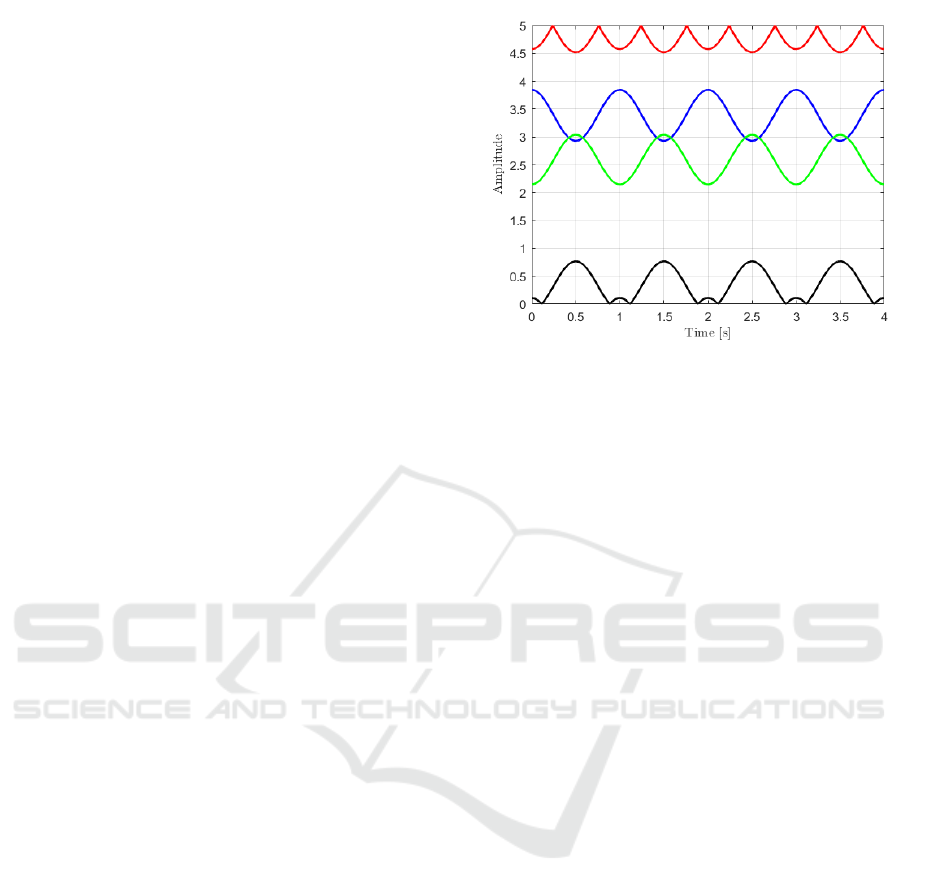
Figure 2: Numerical example of the null-point issue. Sup-
posed a cosine-law displacement of the target, the channels
in red and in black are affected by null points and the result-
ing signal is no more a cosine function.
Protection (ICNIRP) guideline (Jammet et al., 1984).
Both the transmitted and back-scattered waves are
then sent to a square-wave shaping detector (SWSD)
and converted into square waves with amplitude be-
tween 0 and 5 V. Finally, the signals are sent to an ex-
clusive OR logic port (XOR) which provides a signal
related to the phase difference between the transmitter
and the receiver.
In case of no differences, the output will be 0 Volt;
conversely, in case of a half-period delay the result
will be 5 Volt (the maximum value). The former case
results in a null output, which is the aforementioned
null-point. A numerical example of the possible effect
of the null point issue is shown in Fig. 2, in which
the target is moving following a cosine law and the
signal acquired by the red and black channels, which
are effected by the null-point problem, are not cosines
anymore.
A multi-channel system has been used to over-
come this problem, which allows to record signals
at different sensors locations. Therefore, if the null-
point occurs in one channel, it is very unlikely that it
will occur in all of them, having chosen the distances
among transmitter and receivers properly. In particu-
lar, since our purpose at this step is a near range de-
tection, the mutual distances between the transmitter
and the receivers are 1.6, 2.0, 3.0, 3.5 cm for the red,
green, violet and black-coloured sensors respectively.
This particular configuration ensures that there is no
null-point in all the four channels simultaneously if
the target is nearer than 40 cm from the prototype. If
the working distance increases, farther receivers loca-
tions must be considered.
Regarding the ultrasonic sensors, the models
40LT16 and 40LR16 manufactured by SensComp
MUHD: A Multi-channel Ultrasound Prototype for Remote Heartbeat Detection
59
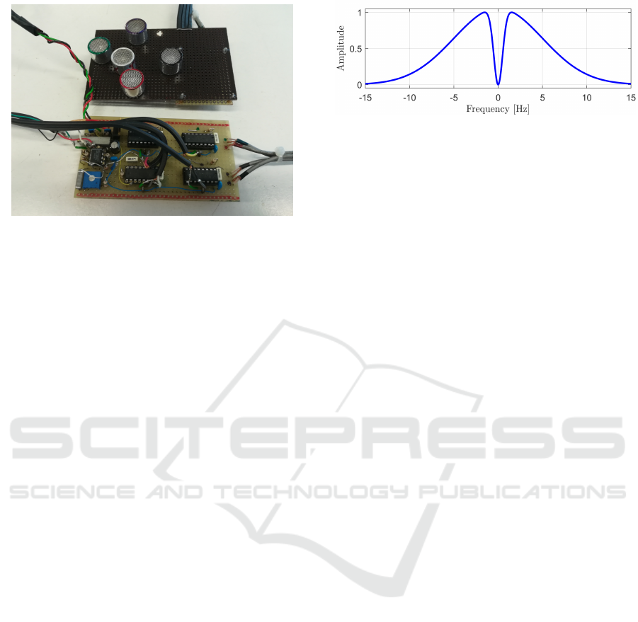
Figure 3: Picture of the prototype. In the top the board with
the US sensors, in the bottom the board with the electronics.
were employed for the transmitter and receivers, re-
spectively. These piezoelectric sensors have a quite
narrow bandwidth of about 2 kHz centred at 40 kHz
with a radiation pattern at -6 dB of approximately
sixty degrees both in the horizonal and vertical axes.
The SWSD electronics is mounted on one board,
while OR logic ports and the electronic components
are placed on a second board. A picture of the com-
plete prototype is shown in Fig. 3. The output signal
of the XOR port is sent to an analog-to-digital con-
verter (ADC) which, in our case is a PCI-6251 board
manufactured by National Instrument. This board has
a 16-bit resolution and a maximum sample rate of
1.25 MS/s. For our measures, the sampling frequency
was fixed at 200 Hz with sixteen-bit precision. A Lab-
VIEW script was used to manage the acquisition rou-
tine. Once acquired, the signals are processed in Mat-
lab (The Mathworks, Inc.).
4 DATA PROCESSING
In order to evaluate the capability of the prototype
to detect the heartbeat, the system was firstly tested
on moving phantoms and then on volunteers. The
complete signal processing is a step-by-step proce-
dure that aims at emphasising the heartbeat compo-
nents in the acquired signals. In this section, some
results and the procedure employed for the data pro-
cessing are reported.
4.1 Acquisition Protocol
The prototype has been tested on 4 male volunteers,
with an age between 30 and 60 years. Per each sub-
ject, two acquisitions of length 60 seconds of the car-
diac signal were recorded. In all the cases the proto-
Figure 4: Band-pass Gaussian-shaped filter for cutting-off
noise and breathing from the signal.
type was placed at 20-cm distance from the pit of the
neck, considering this area as target area. All the mea-
sures were recorded in the same scenario and condi-
tions. The volunteers laid down in a supine position,
breathing normally and relaxed. During the acquisi-
tion, in order to evaluate the performance of the sys-
tem, the ECG signal was also recorded. For this pur-
pose, three electrodes were placed on left and right
arms and on the right leg following the Einthoven’s
triangle. These electrodes are linked with a commer-
cial electronic board which filters and amplifies the
signal. The ECG signal is acquired with the same
DAQ used for the US sensors, guaranteeing the si-
multaneity of all the signals.
4.2 Pre-processing
After acquiring the signals, a filter to cut-off noise
and artifact effects is employed. More in detail, high-
frequency noise and low-frequency residual breathing
components are the main cause of signal degradation.
For the data pre-processing, a modified Gaussian-
shaped band-pass filter was employed whose fre-
quency response is reported in Fig. 4. The bandwidth
of this filter is [0.6, 6] Hz, which is a good compro-
mise between preserving the useful component of the
signal and reducing the amount of noise and breath-
ing effect. Fig. 5 shows a portion of a recorded fil-
tered US signal (in red) overlapped on the reference
ECG signal (in blue). It is worth to note that the sig-
nal measured by the proposed US system has peaks
which have a constant delay with respect to the ECG
ones, and the reason is related to the fact that the two
signals are different, since the former is mechanical,
while the latter is electrical.
4.3 Detection Strategy
The pre-processed data is cut into pieces of equal
length and filtered by means of a moving window.
The length of the window is fixed and properly se-
lected in order to have a region with the presence of
only one peak with the highest probability. The peak
is assumed to correspond to the maximum value in
BIODEVICES 2020 - 13th International Conference on Biomedical Electronics and Devices
60
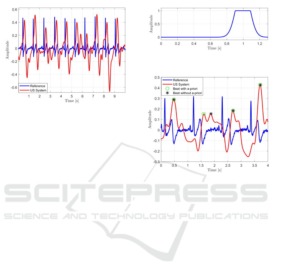
Figure 5: Plot of the reference ECG (blue) and filtered US
(red) signals (ten-second length signals).
each window. It is worth to note that this strategy is an
adaptive one, since after the detection of each heart-
beat, the next window will be starting from the time
instant at which the current heartbeat is estimated. For
the heartbeat detection, a good value for window’s
width seems to be 1.25 s, which works quite well for
healthy patients. However, in presence of two or more
peaks closer than 0.5 second, the one with higher am-
plitude is selected. The length of the moving window,
as well as the peak selection, are easily tunable in case
of patients affected by bradycardia or tachycardia.
4.3.1 Best Channel Selection
The detection strategy proposed previously is charac-
terised by different performance according to the con-
sidered channels. Therefore, it is worth to exploit an
automatic strategy for selecting the best channel per
each measure. To this aim, a two-step procedure was
adopted. Firstly, the recorded signals whose ampli-
tudes are close to the limits of the range [0, 5] Volt
are discarded, since they are intrinsically not reliable.
After that, the signal power in the frequency band-
width [0.9,1.2] Hz is estimated (which represents the
useful bandwidth for healthy people). The higher the
power, the higher the contribution of the cardiac sig-
nal is supposed to be in the overall acquired signal.
This measure represents an indirect evaluation of the
signal to noise (SNR) ratio, so the channel that has
the highest value is selected for the heartbeat detec-
tion step.
4.3.2 A-priori Regularisation Window
Even though the automatic choice of the best chan-
nel assures that the detection step is performed on
the channel with the highest SNR, artifacts and noise
Figure 6: Clipped Gaussian-shaped window employed for
the heartbeat detection step.
Figure 7: Effect of the regularisation window. In blue the
reference signal, in red the US signal, the black stars repre-
sent the beats detected without the use of the a-priori func-
tion, while the green circles are the beats detected by em-
ploying the clipped Gaussian-shaped window.
might still be present in the measures. In order
to make the detection step more robust, a clipped
Gaussian-shaped window is employed. This regulari-
sation window emphasises parts of the signal in which
the peaks are expected to be located with higher prob-
ability. To this aim, every searching window is mul-
tiplied with this window centred at the expected po-
sition of the beat. This instant is calculated using the
distance evaluated at the previous detected beat.
Fig. 6 shows an example of application of this
window in case that the expected beat is centred at
1 second from the previous one. Fig. 7 illustrates
a comparison of the heartbeat detection step by em-
ploying a clipped Gaussian-shaped function and with-
out any prior information. It is clear from the figure
that the detection strategy without the regularisation
window is not able to properly identify the heartbeat
peak.
4.4 Results
After the heartbeat detection step, an average BPM
value was calculated per each case. A comparison be-
tween the average BPMs evaluated via standard ECG
MUHD: A Multi-channel Ultrasound Prototype for Remote Heartbeat Detection
61

Table 1: Mean of heartbeats [BPM] measured by the ECG and the proposed US system.
Subject 1 Subject 2 Subject 3 Subject 4
Acq.1 Acq.2 Acq.1 Acq.2 Acq.1 Acq.2 Acq.1 Acq.2
ECG 64.10 65.55 57.28 58.04 67.30 70.07 56.74 63.83
US 64.10 65.55 57.28 58.18 67.42 70.09 56.80 63.89
and the ones by means of the prototype are presented
in Table 1. The table shows that the results obtained
by the proposed system are very similar to the ones
obtained by reference ECG with a very low error
(maximum absolute error of 0.12 s).
5 CONCLUSIONS
This manuscript presents a US prototype for non-
contact heartbeat detection. The system measures
skin displacement due to the pressure waves gen-
erated by the cardiac activity and exploits a multi-
channel architecture to overcome the null-point issue
and a windowing procedure for enforcing the heart-
beat detection. The prototype was built and tested on
four volunteers. Results are encouraging, as the sys-
tem was able to provide a performance level in detect-
ing heartbeats comparable to standard electrocardio-
graphy. Further work will focus on the improvement
of system robustness to subject movements and ex-
ternal artifacts, as well as on increasing the working
distance of the system.
ACKNOWLEDGEMENTS
The work has been partially supported by the funding
program “Bando di sostegno alla ricerca individuale
per il triennio 2015-2017” of the University of Napoli
Parthenope.
REFERENCES
Arcelus, A., Sardar, M., and Mihailidis, A. (2013). Design
of a capacitive ecg sensor for unobtrusive heart rate
measurements. In 2013 IEEE International Instru-
mentation and Measurement Technology Conference
(I2MTC), pages 407–410.
Bonde, A., Pan, S., Jia, Z., Zhang, Y., Noh, H. Y., and
Zhang, P. (2018). Vvrrm: Vehicular vibration-based
heart rr-interval monitoring system. In Proceedings of
the 19th International Workshop on Mobile Comput-
ing Systems & Applications, pages 37–42. ACM.
Droitcour, A., Lubecke, V., Lin, J., and Boric-Lubecke, O.
(2001). A microwave radio for doppler radar sensing
of vital signs. In International Microwave Symposium
Digest, volume 1, pages 175–178. IEEE.
Droitcour, A. D., Boric-Lubecke, O., Lubecke, V. M., Lin,
J., and Kovacs, G. T. (2004). Range correlation
and I/Q performance benefits in single-chip silicon
doppler radars for noncontact cardiopulmonary moni-
toring. IEEE Transactions on Microwave Theory and
Techniques, 52(3):838–848.
Gu, C., Li, C., Lin, J., Long, J., Huangfu, J., and
Ran, L. (2010). Instrument-based noncontact doppler
radar vital sign detection system using heterodyne
digital quadrature demodulation architecture. IEEE
Transactions on Instrumentation and Measurement,
59(6):1580–1588.
Hassan, M. A., Malik, A. S., Fofi, D., Saad, N. M., Ali,
Y. S., and Meriaudeau, F. (2017). Video-based heart-
beat rate measuring method using ballistocardiogra-
phy. IEEE Sensors Journal, 17(14):4544–4557.
Jammet, H. P., Bosnjakovic, B. F. M., Czerski, P., Faber,
M., Harder, D., Marshall, J., Repacholi, M. H., Sliney,
D. H., and Villforth, J. C. (1984). Interim guidelines
on limits of human exposure to airborne ultrasound.
international non-ionizing radiation committee of the
international radiation protection association. Health
Physics, 46:969–974.
Kim, S. and Nguyen, C. (2004). On the development of
a multifunction millimeter-wave sensor for displace-
ment sensing and low-velocity measurement. IEEE
Transactions on Microwave Theory and Techniques,
52(11):2503–2512.
Konno, K. and Mead, J. (1967). Measurement of the sepa-
rate volume changes of rib cage and abdomen during
breathing. Journal of applied physiology, 22(3):407–
422.
Kranjec, J., Begus, S., Drnovsek, J., and Gersak, G. (2014).
Novel methods for noncontact heart rate measure-
ment: A feasibility study. IEEE Transactions on In-
strumentation and Measurement, 63(4):838–847.
Massagram, W., Lubecke, V. M., and Boric-Lubecke, O.
(2009). Microwave non-invasive sensing of respira-
tory tidal volume. In Annual International Confer-
ence of Engineering in Medicine and Biology Society,
pages 4832–4835. IEEE.
Massaroni, C., Lopes, D. S., Lo Presti, D., Schena, E.,
and Silvestri, S. (2018a). Contactless monitoring of
breathing patterns and respiratory rate at the pit of the
neck: A single camera approach. Journal of Sensors,
2018.
Massaroni, C., Venanzi, C., Silvatti, A. P., Lo Presti, D.,
Saccomandi, P., Formica, D., Giurazza, F., Caponero,
M. A., and Schena, E. (2018b). Smart textile for
respiratory monitoring and thoraco-abdominal mo-
BIODEVICES 2020 - 13th International Conference on Biomedical Electronics and Devices
62

tion pattern evaluation. Journal of biophotonics,
11(5):e201700263.
Min, S. D., Kim, J. K., Shin, H. S., Yun, Y. H., Lee, C. K.,
and Lee, M. (2010). Noncontact respiration rate mea-
surement system using an ultrasonic proximity sensor.
IEEE Sensors Journal, 10(11):1732–1739.
Obeid, D., Sadek, S., Zaharia, G., and El Zein, G. (2010).
Multitunable microwave system for touchless heart-
beat detection and heart rate variability extraction. Mi-
crowave and optical technology letters, 52(1):192–
198.
Silbernagl, S. and Despopoulos, A. (2015). Color Atlas of
Physiology. Thieme.
Suzuki, S., Matsui, T., Imuta, H., Uenoyama, M., Yura, H.,
Ishihara, M., and Kawakami, M. (2008). A novel auto-
nomic activation measurement method for stress mon-
itoring: non-contact measurement of heart rate vari-
ability using a compact microwave radar. Medical &
biological engineering & computing, 46(7):709–714.
Varanini, M., Berardi, P., Conforti, F., Micalizzi, M.,
Neglia, D., and Macerata, A. (2008). Cardiac and
respiratory monitoring through non-invasive and con-
tactless radar technique. In Computers in Cardiology,
pages 149–152. IEEE.
Xiao, Y., Lin, J., Boric-Lubecke, O., and Lubecke, M.
(2006). Frequency-tuning technique for remote de-
tection of heartbeat and respiration using low-power
double-sideband transmission in the Ka-band. IEEE
Transactions on Microwave Theory and Techniques,
54(5):2023–2032.
MUHD: A Multi-channel Ultrasound Prototype for Remote Heartbeat Detection
63
