
Development of a New EMG Wearable Sensor for Myoelectric
Control
Clive Seguna, Steve Buhagiar, Jeremy Scerri and Kris Scicluna
Institute of Engineering and Transport, Electrical and Electronics, MCAST,
Corradino Hill Paola, Malta
Keywords: e-Health, Wireless, Wearable, Sensing, EMG, ECG, Telemetry.
Abstract: The application of wireless technology to monitor and record high quality real-time signals is playing an
important role in today`s world. Various applications such as electromyography and electrocardiography
require low-power and low-voltage portable wireless sensors for remote e-health monitoring. The use of such
technology allows patients with muscle or heart problems to be monitored from the comfort of their home.
Additionally, wireless implantable electromyogram sensing is also integrated in the design of intelligent
myoelectric control for powered prostheses. The specifications within such applications constrain the design
and development of wearable electromyographic sensors. This work presents a low-cost, portable, wireless
non-invasive 8-channel system to monitor and classify electromyographic signals related to hand or finger
movement. The proposed system operates at 1.0 V and draws a current of 1 mA in power-down mode. The
paper also discusses the hardware and software implementation details and presents various measurement
results. This work concludes through feature comparison with other similar technologies in the market.
1 INTRODUCTION
Wearable technology has been trending in healthcare
and myoelectric applications for the last decade.
Electromyography (EMG) sensors have been
succesfully used in assistive and therapeutic
healthcare. Such applications impose several
challenges on the development of such wearable
technology for the continuous daily health
monitoring; these include small form factor, minimal
power consumption, portability and extended battery
life. EMG signals are distributed in a frequency range
between 10 to 500 Hz. Additionally, EMG sensors are
also used in motion therapies in order to track patient
motion and applied forces (Nikolic, 1994), (Suster,
2007), (Cong, 2009), (Kamali, 2014).
EMG sensor which are expensive and have a large
form factor are already available in the market.
However, researchers are finding challenges in
designing and developing low-cost, low-voltage, and
small form-factor sensors that are able to detect finger
and hand movement (Nair, 2010), (Lui, 2000).
Such requirements are critical for wearable and
portable applications. Various EMG-based control
techniques apply the use of pattern recognition,
mapping techniques or models (Burke, 2004), neural
nets and time domain (Nagaraju, 2010), (Benatti,
2017), (Teng, 2014) analysis for the classification of
hand or finger movement (Cappellari, 2018),
(Berezhnoy, 2018), (Bembli, 2019), .This work
presents a new low-cost, low-voltage EMG sensor
designed to classify finger and hand movement in a
patient. Through the use of an LPC824 based
microcontroller system and the implementation of
custom signal conditioning circuitry the developed
non-invasive EMG wireless sensor is able to capture
and process 8 multiplexed EMG signals. The pre-
processed EMG data is then trasmitted wirelessly
over Bluetooth for the control and activation of a
robotic manipulator. Such features makes this sensor
suitable for various applications including muscle
movement and myoelectric control at low-cost by just
using commercial off-the shelf components.
Classification of finger and hand movement is
implemented through amplitude and time-domain
analysis (Mert et al., 2018).
Section 2 presents the circuit design for the
wireless EMG sensor. Section 3 describes the adopted
time-domain procedure for the classification and
detection of hand or finger movement. A detailed
description related with the measurement results is
given in Section 4.
160
Seguna, C., Buhagiar, S., Scerri, J. and Scicluna, K.
Development of a New EMG Wearable Sensor for Myoelectric Control.
DOI: 10.5220/0008979501600164
In Proceedings of the 13th International Joint Conference on Biomedical Engineering Systems and Technologies (BIOSTEC 2020) - Volume 1: BIODEVICES, pages 160-164
ISBN: 978-989-758-398-8; ISSN: 2184-4305
Copyright
c
2022 by SCITEPRESS – Science and Technology Publications, Lda. All rights reserved
2 EMG SENSOR CIRCUIT
DESIGN
This section describes the design and implementation
details related with the developed EMG sensory
module. The acquisition of the 8-channel EMG
signals is performed through the use of wet electrodes
connected in uni-polar configuration and then to an
instrumentation amplifier (IA) with a common-mode
rejection ratio (CMRR) of 120 dB, followed by
amplification and filtering stages. This arrangement
contributes to the reduction of common mode noise
which is present on both electrodes while retaining
the signal of interest. Further reduction in circuit
design is achieved through the use of a multiplexing
circuit that allows the switching between the 8-
channel selectable electrode signals. The
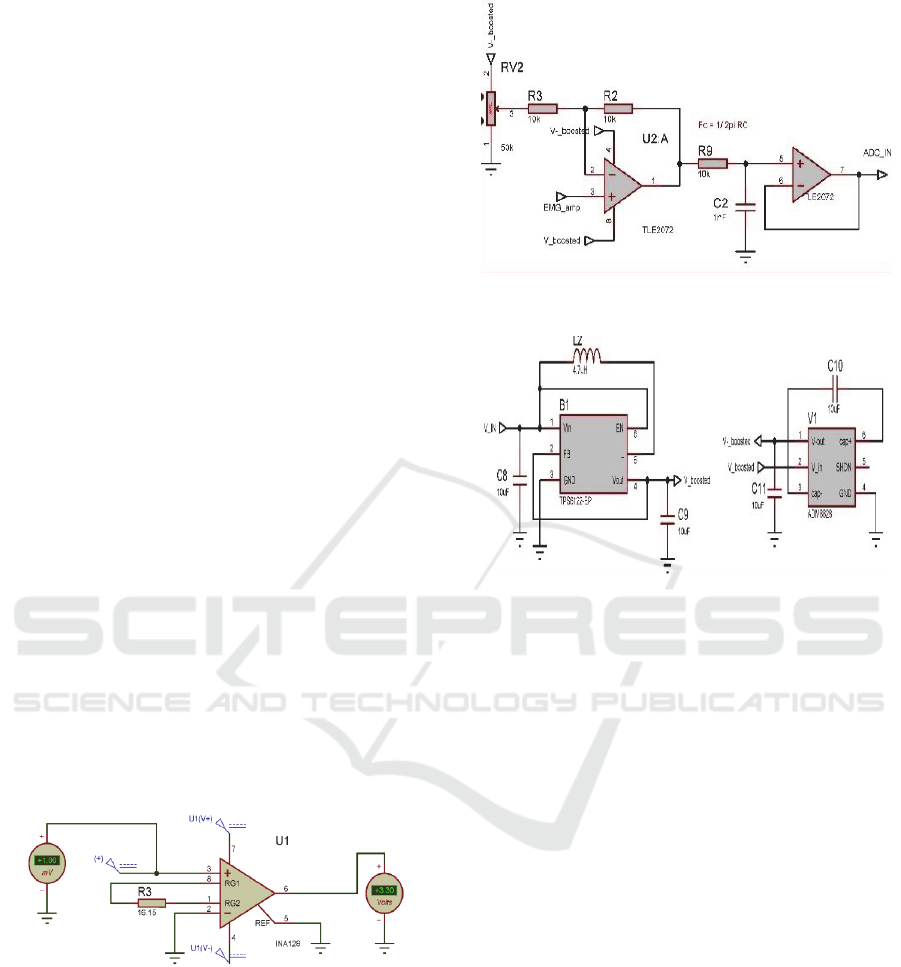
instrumentation amplifier circuitry shown in Figure 1
(gain of 3300), yields a maximum output voltage of
3.3 V peak to peak. A DC offset of 1.65 V is
introduced so that the full range of the 3.3 V
Analogue-to-Digital Converter (ADC) on the
LPC824 microcontroller is used. The DC offset
circuit is followed by an first order low-pass filter
(bandwidth f
3dB
= 15 kHz) as shown in Figure 2. The
adopted LPC824 ARM based Cortex M0+
microcontroller operates through an internal RC
oscillator running at 12 MHz, pre-scaled to 30 MHz
using an internal PLL. Additionally, this
microcontroller supports Direct Memory Access
(DMA), thus enabling the processing of 14
th
order
band-pass digital filter at a sampling frequency of 1.5
kHz. The dual rail supply voltage for instrumentation
amplifier is ± 5.0 V.
Figure 1: EMG Instrumentation Amplifier Circuit.
The TPS6122 buck-boost DC-DC converter circuitry
has a minimum input voltage of 0.7 V and output
voltage range of 1.8 to 5.5 V with a quiescent current
of 5.5 µA.
The analog stage requires a dual rail supply,
therefore a buck-boost convertor (negative supply) is
used to achieve the required voltages of ± 5.0 V. The
ADM8829 charge-pump voltage inverter changes the
input voltage outputted from the TPS6122 device into
Figure 2: DC offset and Low Pass Filter circuitry.
Figure 3: Buck-Boost Converter.
a negative voltage, creating a dual rail supply voltage
for the IA and op-amps.
The ADG708 multiplexer is used to switch
between selectable 8-channel electrodes whose
output is to be sampled by the ADC, and then filtered
through the 14
th
order digital infinite-impulse
response (IIR) band-pass digital filter using the
LPC824 microcontroller (bandwidth f1
3dB
= 25 Hz,
f2
3dB
= 225 Hz ). The filtered EMG data is then
transmitted from the LPC824 device to the HC06
bluetooth module and then received by a wireless
client device.
The maximum switching time in between
multiplexer channels is 14 ns when running on 5 V
and a typical power consumption of 1 µA.
Figure 5 illustrates the top and bottom views for
the manufactured system with a small form-factor of
33 by 20 mm. Two switch push-buttons, are used to
program the microcontroller. The internal LPC824
direct Memory Access (DMA) module allows
transfer of digital EMG data at a high transfer rate
with the intervention of very few CPU cycles. Test
pins were included in the module so to directly
monitor and record the amplified and filtered EMG
signals through an oscilloscope.
Development of a New EMG Wearable Sensor for Myoelectric Control
161
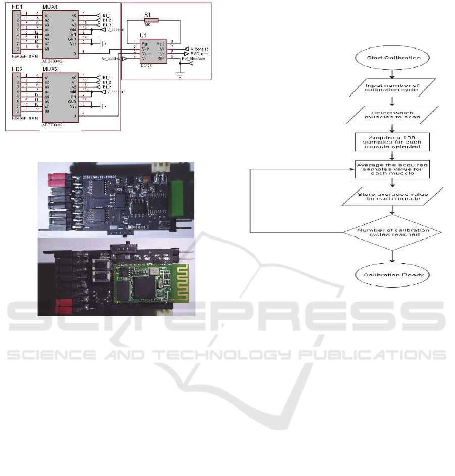
Figure 4: INA128 and multiplexing stage.
Figure 5: Top and bottom view of the wearable EMG sensor
with dimension 33mm by 20 mm.
3 EMG SENSOR
CLASSIFICATION
Analysis of EMG signals was performed using two
pairs of electrodes placed over the forearm muscle,
which is mostly active when moving the arm wrist.
The raw EMG signal was processed through root
mean square calculation. Classification of wrist and
hand movement was done through time-domain
amplitude analysis. A system calibration procedure
shown in Figure 6 allows the recognition of wrist or
hand movement via amplitude analysis. The
implementation for amplitude analysis identifies and
configures the thresholds measured when certain
hand gesture movements are made. Calibration
process follows electrode placement. This process
consisted of contracting the wrist in three different
positions multiple times and one at a time. With each
contraction, the amplitudes acquired from all
electrodes being recorded. This process was repeated
for a pre-defined amount of repetitions so to establish
the required thresholds. The amplitude analysis is
performed prior to the signal being filtered and then
Root Mean Squared; a moving average can be applied
to the signal if needed.
Figure 6: Calibration Procedure for the classification of
hand movement.
4 MEAUREMENT RESULTS
An illustration of the amplified raw, DC shifted EMG
signal for various hand movements is shown in Figure
7. This signal represents the electrical currents
generated by the muscle activity being controlled by
the nervous system and is also depended on the
anatomical and physiological properties of the
muscles. Additionally, the shown EMG signal in
Figure 7 has been filtered from noise being generated
from various tissues. For testing purposes, a 3D-
printed five degrees of freedom robotic manipulator
is to be controlled through six analogue or PWM
inputs located on the robot controller.
The acquired EMG myoelectric signals from 4
different channels are shown in Figure 8. The
calibration procedure was performed for adaptively
setting the required channel amplitude thresholds
needed for the classification of three hand
movements. Classification data is wirelessly
transmitted to a bluetooth client device located on the
robotic manipulator and controlled using an
embedded controller.
BIODEVICES 2020 - 13th International Conference on Biomedical Electronics and Devices
162
Figure 7: Amplitude response of filtered and smoothened
Raw EMG signal.
Examples of three different classified hand
motions are shown in Figure 9. The fist motion will
control the opening and closing of the claw actuation,
while two other hand movements rotates are used to
control the angular position robotic arm
that is
clockwise or counter-clockwise. The same
classification procedure has also been tested and
adopted for the classification of finger movement.
Through exstensive experimentation repetitive
measurement and performance results were noted.
5 DISCUSSION AND
CONCLUSION
In this work, the successful development of a low cost
and wearable 8-channel sEMG data acquisition
system was presented along with the implementation
of an adaptive threshold setting algorithm for the
classification and contraction detection of hand or
wrist movement. A feature comparison of the
proposed system with other similar sEMG sensors
including commercially available products in terms
of bandwidth, operating voltage, size, and contraction
detection is shown in Table 1. Such comparison,
illustrates that the developed non-invasive wearable
sEMG sensor has the smallest form factor operates
and operates at a low supply voltage of 1.0 V using
just one single-cell AAA battery. The developed
EMG sensor has also a very low weight of 6 grams,
four times less when compared to other similar work.
Additionally, through exstensive testing and from
the illustrated measurement results the threshold
setting amplitude analysis classification algorithm is
satisfactorily detects contractions and recognizes
wrist or finger movement.
Figure 8: EMG measurements for four EMG channels (mV
versus time ms).
Figure 9: Control of robotic manipulator through developed
EMG sensor.
Table 1 : Comparison with other similar Systems.
This
work
sEMG
Sensor
(Seguna,
2018
)
Myo
Armband
Hercules
(Mert, 2018)
Classification
of
Hand/Finger
Movement
Yes Yes No No
Contraction
Detection
Yes Yes No Yes
Wearable Yes Yes Yes Yes
Bandwidth
(Hz)
1200 20-589 - 20-500
Supply
Voltage
1.0 V 2.5 V 3.7 V 3.7 V
Dimensions
L x W (mm)
20 x 33 45 x 25
190 x 340 -
Weight
(grams)
6 24
93 -
Battery
Type
AAA
(x1)
-
Built-in
lithium
Ion
AA
(x2)
Development of a New EMG Wearable Sensor for Myoelectric Control
163

REFERENCES
Nikolic, R., et al.,“Instrumentation for ENG and EMG
recordings in FES systems”, IEEE Trans. Biomedical
Engineering, v. 41, nr. 7, pages 703-706, 1994.
Suster, M., et al., “A Wireless Strain Sensing Microsystem
with External RF Powering and Two-Channel Data
Telemetry Capability,” ISSCC, 2007, pages 380-381.
Cong, P., et al., “A Wireless and Batteryless 130 milligram
300μW 10-bit Implantable Blood Pressure Sensing
Microsystem for Real-time Genetically Engineered
Mice Monitoring”, ISSCC, 2009, pages 428-429.
Kamali, T., et al., ,“A multi-classifier approach to MUAP
classification for diagnosis of neuromuscular
disorders,” IEEE Trans. Neural Syst. Rehabil. Eng.,
vol. 22, no. 1, pages 191–200, Jan. 2014.
Nair, S., et al., “The application of machine learning
algorithms to the analysis of electromyographic
patterns from arthritic patients,” IEEE Trans. Neural
Syst. Rehabil. Eng., vol. 18, no. 2, pages 174–184, Apr.
2010.
Liu, W. and Humayun, M. S, “Retinal Prosthesis”, ISSCC,
2004, pages 218 – 225.
Burke, M., et al., “A micropower dry-electrode ECG
preamplifier,” Biomedical Engineering, IEEE
Transactions on, vol. 47, 2000, pages 155 –162.
Nagaraju, M., et al., “Circuit techniques for wireless
bioelectrical interfaces,” in 2010 International
Symposium on VLSI Design Automation and Test
(VLSI-DAT), 2010, pages 117 –120.
Benatti, S., et al., “A prosthetic hand body area controller
based on efficient pattern recognition control
strategies,” Sensors, vol. 17, no. 4, pages 2-17–4-17,
2017.
Teng, S., L, et al., “Programmable EXG biopotential front-
end IC for wearable applications”, IEEE Trans.
Biomed. Circuits Syst., vol. 8, no. 4, pages 543–551,
Aug. 2014.
Cappellari, P., et al., “Identifying Electromyography Sensor
Placement using Dense Neural Networks”, in
Proceedings of the 7th International Conference on
Data Science, Technology and Applications – pages
130-141, 2018.
Berezhnoy, V., Popov D., Afanasyev I. “The Hand-gesture-
based Control Interface with Wearable Glove System”,
in Proceedings of the 15th International Conference on
Informatics in Control, Automation and Robotics -
Volume 2: ICINCO, pages 458-465, 2018.
Bembli, S., et al., “A Terminal Sliding Mode Control using
EMG Signal: Application to an Exoskeleton-Upper
Limb System”, in Proceedings of the 16th International
Conference on Informatics in Control, Automation and
Robotics - Volume 2: ICINCO, pages 559-565, 2019.
Seguna, C., et al., “Development of a New Low-Cost EMG
Monitoring System for the Classification of Finger
Movement”, 2018 New Generation of CAS (NGCAS),
pp. 126-129, 2018.
Mert, E., et al., “An Embedded, Eight Channel, Noise
Cancelling, Wireless, Wearable sEMG Data
Acquisition System with Adaptive Muscle Contraction
Detection”, IEEE transactions on biomedical circuits
and systems, 2018.
BIODEVICES 2020 - 13th International Conference on Biomedical Electronics and Devices
164
