
RuleDSD: A Rule-based Modelling and Simulation Tool for DNA Strand
Displacement Systems
Vinay Gautam
a
, Shiting Long and Pekka Orponen
b
Department of Computer Science, Aalto University, 00076 Aalto, Finland
Keywords:
DNA Strand Displacement, DSD Modelling and Simulation, PySB, Rule-based Model, BioNetGen.
Abstract:
RuleDSD is a tool to support the rule-based modelling and simulation of DNA Strand Displacement (DSD)
systems. It constitutes a software pipeline programmed in Python and integrated with PySB, a standard frame-
work for rule-based modelling of biochemical systems. The input to RuleDSD is a domain-level model of
a DSD system, where each initial DNA complex is described at the level of named pairing domains. The
RuleDSD pipeline converts these domain-level descriptions into a canonical graph representation, and based
on this performs a full state-space enumeration of DNA species reachable by applying the basic rules of DNA
strand displacement reactions to the ensemble of initial species. The resulting chemical reaction network is
then converted into a BioNetGen model and imported into the PySB framework for deterministic or stochastic
simulation and analysis. Altogether, RuleDSD thus provides a customised front-end for rule-based modelling
and simulation of DNA Strand Displacement systems using the BioNetGen simulation engine, and opens up
further possibilities for harnessing the well-established rule-based modelling methods and tools that can easily
be utilised through the PySB wrapper.
1 INTRODUCTION
DNA molecules have proven to be a versatile sub-
strate for engineering synthetic biochemical systems
with programmable dynamic behaviours (Zhang and
Seelig, 2011). Over two decades, a variety of DNA
Strand Displacement (DSD) systems, such as molec-
ular motors (Yurke et al., 2000), walkers (Shin and
Pierce, 2004), DNA logic circuits (Seelig et al., 2006;
Qian and Winfree, 2011), enzyme-free catalytic sys-
tems (Zhang et al., 2007; Yin et al., 2008), and
systems implementing Chemical Reaction Network
(CRN) dynamics (Chen et al., 2013; Srinivas et al.,
2017) have been constructed. It has been demon-
strated theoretically that any CRN can be converted
into a DSD system of approximately equivalent be-
haviour (Soloveichik et al., 2010; Cardelli, 2013).
The DNA-based reaction mechanism of Toehold-
mediated DNA Strand Displacement (Yurke and
Mills, 2003; Zhang et al., 2007) provides an expe-
dient reaction toolbox (illustrated in Section 2) for
designing DSD systems. Starting with an initial set
of domain-level DNA molecular species and the set
a
https://orcid.org/0000-0003-1506-2071
b
https://orcid.org/0000-0002-0417-2104
of DNA interactions based on the DSD reaction tool-
box, one can formally derive a reaction network of
the DSD system by enumerating all possible reactions
between DNA species (Phillips and Cardelli, 2009;
Kawamata et al., 2011; Grun et al., 2015a). The de-
rived network provides a basis for both qualitative and
quantitative modelling and analysis of the DSD sys-
tem. The network information can, e.g., be used for
computing the state space of the DSD system, verify-
ing its input/output behaviour, and checking that the
derived behaviour of a DSD system corresponds to
the designer’s intentions.
Although small DSD systems can be modelled
by hand (Seelig et al., 2006; Zhang et al., 2007),
automated design and modelling frameworks are
needed for large, complex DSD systems (Yin et al.,
2008; Qian and Winfree, 2011; Chen et al., 2013;
Srinivas et al., 2017). Recently, several modelling
methods have been proposed and implemented as
software tools: Visual DSD (Lakin et al., 2011),
KinDA (Berleant et al., 2018), and DyNAMiC Work-
bench (Grun et al., 2015b). Visual DSD originally
allowed the modelling of only very simple DSD sys-
tems based on single-stranded DNA and partially
double-stranded DNA structures. However, over the
years, the tool has gone through several changes to
158
Gautam, V., Long, S. and Orponen, P.
RuleDSD: A Rule-based Modelling and Simulation Tool for DNA Strand Displacement Systems.
DOI: 10.5220/0008979101580167
In Proceedings of the 13th International Joint Conference on Biomedical Engineering Systems and Technologies (BIOSTEC 2020) - Volume 3: BIOINFORMATICS, pages 158-167
ISBN: 978-989-758-398-8; ISSN: 2184-4305
Copyright
c
2022 by SCITEPRESS – Science and Technology Publications, Lda. All rights reserved

enable the modelling of DSD systems consisting of
DNA loops, multi-branch DNA structures (Petersen
et al., 2016; Spaccasassi et al., 2018), and tethered
structures designed to interact locally (Lakin et al.,
2014). The other two DSD system design software
tools, KinDA and DyNAMiC Workbench, also pro-
vide integrated frameworks for the design, modelling
and analysis of a DSD system at the domain and se-
quence levels. Both these tools use an alternative enu-
meration method based on time-scale separation of
the reactions, which reduces the state-space of DSD
systems by condensing reactions leading to combina-
torial DNA structures (Grun et al., 2015a)
Domain-level modelling of DSD system be-
haviour is currently facing two main problems. First,
the increasingly large number of reactions consid-
ered between DNA species makes full enumeration
of a system’s state-space computationally infeasible.
To address this issue, (Kawamata et al., 2011) and
(Grun et al., 2015a) have proposed alternative meth-
ods to enumerate state spaces of DSD systems. Sec-
ond, as the complexity of DSD systems continues to
increase, new DNA structures with loops (Yin et al.,
2008), multiple branches (Kotani and Hughes, 2017)
and even pseudoknots (Bui et al., 2017) are used in the
implementation of DSD systems. Although the mod-
elling of DSD systems with such DNA structures was
previously not supported by any of the existing DSD
modelling tools, new implementation methods (Pe-
tersen et al., 2016; Spaccasassi et al., 2018) have re-
cently begun to address the issue.
In the field of biochemical system modelling,
rule-based models, such as BioNetGen (BNGL, in
short) (Faeder et al., 2009) and Kappa (Danos and
Laneve, 2004) have successfully employed methods
to address similar issues. For example, rule-based
models use a concise representation of combinatorial
structures and compact sets of rules to encode a large
number of biochemical interactions. In the present
work, we model DSD systems using a rule-based ap-
proach (Faeder et al., 2009). First, domain-level DNA
species are described using a representation scheme
inspired by rule-based models, as described in (Pe-
tersen et al., 2016). These textual descriptions are
then abstracted into a graph representation, which re-
duces structurally equivalent species representations
to a canonical format. Next, new DNA species are
created by applying graph rewriting rules that are
based on a set of generic DSD reaction types. This
graph processing produces a list of DNA species and
their DSD reaction network, which can be further
translated into the BNGL format and simulated using
the BNGL simulation engine. We provide a full soft-
ware pipeline for this rule-based DSD modelling ap-
proach, integrated with the PySB framework (Lopez
et al., 2013). The main contributions of this work
are twofold. First, the modelling approach discussed
here is general. Second, the work connects the task
of DSD modelling directly to the broader rule-based
modelling frameworks. Therefore, DSD models can
easily be imported to any of the engines developed so
far, or to be developed in future, for rule-based mod-
elling without need to develop own simulators.
In the following, Section 2 reviews the back-
ground on DSD systems, the mechanism of toehold-
mediated strand displacement, the DSD reaction tool-
box, domain-level representation of DSD systems,
and provides an overview of the rule-based modelling
approach. Section 3 outlines our RuleDSD pipeline
for modelling and simulation of domain-level DSD
systems and describes some implementation details
of the pipeline. Section 4 demonstrates simulation
results on a few example DSD systems. Section 5
concludes with some general observations and future
work.
2 BACKGROUND
We start our discussion by describing the terminol-
ogy and conventions used in this paper. We then
present the concept of domain-level design of DSD
systems and illustrate an established toolbox of DSD
reactions. We also outline a domain-level description
language for DSD models. At the end of the section,
the rule-based modelling approach and the BioNet-
Gen framework are briefly introduced.
2.1 DNA Strand Displacement Systems
In the domain-level design of Figure 1 and other de-
signs presented in the paper, each DNA strand is de-
noted by a line segment, with the 3’ end marked by
a half-arrowhead. Lowercase letters and numbers
are used as domain names, and complementary do-
mains are indicated by asterisks. Short “toehold” do-
mains are indicated by appending a caret (ˆ) to their
name, for example a toehold domain x would be rep-
resented as xˆ and its complement as xˆ
∗
. Double-
stranded DNA regions appear as two anti-parallel
line segments. We use the terms DNA species and
DNA complex interchangeably in the case of multi-
stranded DNA molecules, but DNA species contain-
ing only single DNA strands are explicitly mentioned
as single-stranded DNA.
Over the years, theoretical and experimental stud-
ies have established a toolbox of elementary DNA
reactions comprising both inter- and intramolecular
RuleDSD: A Rule-based Modelling and Simulation Tool for DNA Strand Displacement Systems
159
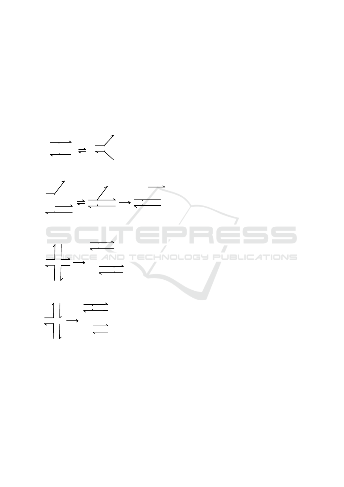
DNA interactions, as shown in Figure 1. The first
two mechanisms in the toolbox, the binding reaction
(RB) and the unbinding reaction (UR), are illustrated
by the domain-level schema in Figure 1a. In the RB
reaction, two single-stranded DNA molecules xˆ y and
xˆ
∗
z which contain matching complementary domains
xˆ and xˆ
∗
undergo a bimolecular reaction that pro-
duces a duplex combining the domains. The RU pro-
cess, which is the reverse of RB, is a unimolecular
reaction in which the duplex dissociates into its con-
stituent DNA strands.
x^
y
x^*
z
x^
y
x^*
z
RB
x^
y
x^*
y
y*
x^
x^*
y
y*
y
RU
RB
RU
x^
x^*
y
y*
y
R3
x^
x^*
y^
y^*
z
z*
z*
z
R4
x^
x^*
y^
y^*
z
z*
z*
z
x^
x^*
z
z*
z*
z
R4
x^
x^*
z
z*
z*
z
(a)
(b)
(c)
(d)
Figure 1: A toolbox of DSD reactions. (a) Binding and
unbinding reactions between two separate DNA strands.
(b) The toehold-mediated strand displacement process be-
tween a partially double-stranded DNA complex and a DNA
strand: an initiating toehold binding/unbinding is followed
by a 3-way branch migration. (c) A 4-way branch migra-
tion reaction between two DNA complexes each having two
DNA strands with mutually complementary domains. (d)
A variant of 4-way branch migration, where the two DNA
complexes are bound by a single toehold domain.
Figure 1b illustrates the key DSD pro-
cess of Toehold-mediated Strand Displacement
(TSD) (Yurke and Mills, 2003; Zhang et al., 2007)
that introduces dynamic control over the interactions
of DNA strands and consists of two reaction steps:
(1) toehold binding, and (2) branch migration. In
the TSD process, a short single-stranded toehold
domain xˆ
∗
serves as a binding site within a partially
double-stranded DNA molecular complex. The
toehold in the DNA complex co-localizes another
single-stranded DNA molecule, the invader or signal
strand xˆy. The toehold binding catalyzes a unimolec-
ular 3-way branch migration reaction (R3) (Zhang
et al., 2007), which releases the previously bound
DNA strand y. Another type of branch migration pro-
cess, a 4-way migration (Panyutin and Hsieh, 1994;
Kotani and Hughes, 2017) (R4), occurs when two
double-stranded DNA molecules that have mutually
complementary DNA strands exchange their strands
(Figure 1c, d).
Toehold domains play a major role in the design
of programmable DSD systems. First, their length
and sequence composition have a significant influence
over the kinetic rate of strand displacement (Zhang
et al., 2007): the rate varies million-fold over a toe-
hold length of six bases or less, and saturates for
longer toeholds. Second, toeholds also serve as recog-
nition domains for input signals (Zhang et al., 2007).
While the first feature provides a design mechanism
for programmable kinetic control based on compet-
ing DNA strand displacement reactions (Zhang and
Seelig, 2011), the second feature enables the design of
DNA strand displacement cascades using DNA com-
plexes with inactivated toeholds that are condition-
ally activated as the reaction proceeds (Seelig et al.,
2006). In principle, any mechanism that sequesters
the toehold domain and inhibits its hybridization can
be used for the inactivation. For example, toeholds
can be buried within double-stranded regions (Seelig
et al., 2006) or inside hairpin loops (Dirks et al., 2004;
Yin et al., 2008) to make them inactive.
2.2 Domain-level Description of DSD
Systems
DSD system modelling typically starts with an ab-
stract domain-level description in terms of a set of
DNA molecular species, each consisting of multi-
ple interacting DNA strands. Each DNA strand is
composed of a set of domains (Phillips and Cardelli,
2009), where each domain is functionally distinct and
corresponds to a contiguous sequence of nucleotides.
Domains can repeat within the same DNA strand, or
can appear in different DNA strands, but any two non-
BIOINFORMATICS 2020 - 11th International Conference on Bioinformatics Models, Methods and Algorithms
160

complementary domains are assumed to be mutually
orthogonal, i.e. the DNA sequences representing dif-
ferent domains are presumed to be designed for min-
imal interference as enforced by the Watson-Crick
base-pairing rules.
A domain-level description language called the
DSD language was introduced in (Phillips and
Cardelli, 2009) for formally describing DSD systems
so as to model and analyse their behaviour. Here
we illustrate the syntax of the DSD language briefly
with the examples of DNA molecules shown in Fig-
ure 1. A typical DSD system comprises two types
of DNA species: single-stranded DNA and multi-
stranded DNA complexes. A single-stranded DNA
species with domain sequence d
1
,d
2
....d
n
is repre-
sented as < d
1
d
2
....d
n
> or {d
1
d
2
....d
n
} in 5’-to-3’
or 3’-to-5’ orientation, respectively. For example, the
two single-stranded DNA species in Figure 1a (left)
would be represented as < xˆ y > (upper strand) and
{xˆ
∗
z} (lower strand). Note that since DNA strands
have a rotational symmetry, the two representations
in this case can be used interchangeably. A multi-
stranded DNA complex in the DSD language is repre-
sented as a sequence of segments consisting of either
single-stranded or double-stranded regions. Single-
stranded segments are represented as discussed above,
while the double-stranded segments are represented
as [d
i
], where d
i
is the domain in the upper strand, ori-
ented in the 5’-to-3’ direction. A nick in the upper or
lower strand is represented by ’:’ or ’::’, respectively.
For example, the double-stranded DNA complexes in
Figure 1b would be represented as {xˆ
∗
}[y] (left) and
[xˆ] < y >: [y] (middle).
The syntax of the original DSD language is lim-
ited to describing only simple DNA molecules with-
out multi-branch structures and hairpins. Therefore,
the four-arm DNA structures shown in Figure 1c,d,
and others having hairpins (Yin et al., 2008) could
not be modelled in the original framework. Re-
cently, (Petersen et al., 2016) introduced a modified
DSD language following the bond notation used in
the formal languages of rule-based models, such as
BNGL (Faeder et al., 2009) and Kappa (Danos and
Laneve, 2004). In the modified DSD language a bond
between two domains (d
1
and d
2
) is represented by a
bond label (d
1
!i and d
2
!i, where i is a bond label and
! is a positional operator) that is local to the DNA
species. Note that the two domains could be within a
single DNA strand or in two different DNA strands.
The other notations, such as the representations for
toehold domains and complementary domains remain
the same in the modified language as in the origi-
nal language. However, DSD models are represented
by processes, where a process P is a set of DNA
strands represented as P =< S
1
|S
2
....|S
n
>. In this
framework, DSD systems having DNA species with
arbitrary, complex DNA structures, such as multi-
branches, hairpin loops and pseudoknots can be rep-
resented.
2.3 Rule-based Modelling and BNGL
Rule-based modelling has recently emerged as a pow-
erful method for modelling and analysis of biochemi-
cal systems with complex reaction networks (Chylek
et al., 2014). Rule-based modelling frameworks, such
as BNGL (Faeder et al., 2009) and Kappa (Danos
and Laneve, 2004), are used to develop compact
models of biochemical systems using a finite set of
rules that can encode a large number of biochem-
ical interactions. A rule-based model can be used
to study stochastic and deterministic behaviours of
a given biochemical system. For biochemical sys-
tem with relatively small state-spaces, a system of
equations or an entire reaction network can be ex-
tracted that can further be simulated deterministically
using ODE solvers or stochastically using the Gille-
spie algorithm (Gillespie, 2007). For the modelling
of biochemical systems with large state-spaces, such
as polymerization reactions, network-free simulation
methods (Danos et al., 2007; Sneddon et al., 2011)
have been developed.
Here, we briefly describe the syntax of the BNGL
language. This language describes biochemical sys-
tems in terms of molecules or agents with sites, where
a site can either interact with other sites or manifest
different states. For example, a molecule M
1
with a
binding site b and another site s that can be in three
different states is represented as M
1
(b,s ∼ 0 ∼ 1 ∼ 2).
If there is another molecule M
2
with a matching bind-
ing site b (represented as M
2
(b)), a binding rule be-
tween these two can be written as:
M
1
(b,s ∼ 0 ∼ 1 ∼ 2)+ M
2
(b) → M
1
(b!1).M
2
(b!1) k
b
,
where the LHS represent reactant molecules (sepa-
rated by a ‘+’), the RHS represents a complex of
two molecules (bound by ‘.’), and the k
b
is rate con-
stant associated with the rule. The bond between two
molecules is represented by ‘!1’, where 1 is the bond
label and ‘!’ is a positional operator. The expressive
power in this rule comes from the language’s ability
that enables the rule to be applied to any molecule M
1
that is not bound at site b regardless of the state of s
and whether or not s is bound to another molecule.
Although it seems quite intuitive to apply rule-
based modelling to DSD systems, a direct translation
of DSD models into rule-based models using BNGL
RuleDSD: A Rule-based Modelling and Simulation Tool for DNA Strand Displacement Systems
161
is challenging due to two reasons (Petersen et al.,
2016). First, binding domains in DSD systems have a
spatial ordering, i.e. a binding at one domain enables
a configuration at another domain that may be bound
or free; however, rule-based models so far do not al-
low to encode such spatial aspects into the rule defini-
tions. Second, such translation would require writing
a large number of rules even for small systems due
to the many possibilities of pattern matching between
the sets of domains of two DNA complexes.
3 THE RuleDSD PIPELINE
Here, we introduce RuleDSD, a tool for rule-based
modelling of DSD systems that converts domain-level
DSD models into BNGL models and simulates them
using the PySB framework. The software pipeline, as
illustrated in Figure 3, is developed as a Python pack-
age DSDPy and integrated with the PySB framework.
4
5^
1
6
3^
4
2
2*
3^*
4*
5^*
6
3^
4
2
3^
4
1
2
2
3^
4
2*
3^*
4
5
4*
5^*
2
3^
4
2*
3^*
4*
5^*
(C)
(S)
(P1)
(I1)
(F)
(OP)
(I2)
(W)
1
2
2*
4*
5^*
3^*
4
5^
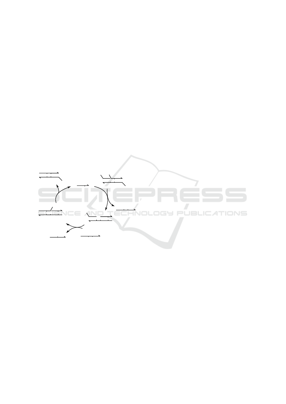
Figure 2: The catalytic DSD system described by (Zhang
et al., 2007), showing the domain-level network derived by
hand. There are three initial DNA species: Catalyst (C),
Substrate (S), and Fuel (F). As the substrate and catalyst re-
act, the displacement reaction produces intermediate DNA
species (I1) and a signal (P1). The DSD system further gen-
erates intermediate species (I2) and output (OP), as Fuel
(F) is consumed by intermediate species I1 to cause sec-
ond displacement reaction. The intermediate DNA species
I2 further turns into a non-reactive waste product (W) and
releases catalyst C back into the cycle.
In this section we discuss the pipeline and its in-
put and output with a representative example of a cat-
alytic DSD system shown in Figure 2. The input to
the pipeline, shown in Figure 4, is a simple text file
that consists of domain-level descriptions of the ini-
tial DNA species, their initial counts/concentrations
and kinetic rates of the DSD reactions. At the other
end of the pipeline, the user can run a script to sim-
ulate the deterministic or stochastic dynamics of the
described DSD system.
The translation/simulation pipeline, as shown in
Figure 3, comprises three modules. The first mod-
ule, DNA species graphs generation, converts the ini-
tial DNA species in a domain-level DSD model to a
canonical graphs representation. The second module,
DSD network generation, reads these input graphs
and transforms them using rules from the DSD reac-
tion toolbox to produce a netlist (a list of DNA species
and a corresponding reaction network) that represents
the full state-space of the DSD system. The output
from this module is a text file consisting of a list of
domain-level DNA species produced from graph pro-
cessing and chemical reactions between these species
with their kinetic rates. The final module, BNGL-
based simulation, reads the DSD netlist and generates
a PySB model in Python that can be simulated using
ODE-based or BNGL-based simulators in the PySB
framework.
3.1 The Strand Graph and the Bond
Graph
The first module in the RuleDSD pipeline, shown in
Figure 3, is a converter that reads the domain-level
DSD descriptions of the initial DNA species of our
representative example of a catalytic DSD system and
creates two types of abstract representations called
the Strand Graph (SG) and Bond Graph (BG) and
displayed in Figure 5a and b, respectively. For the
domain-level description of DSD systems, we use a
modified representation syntax based on article (Pe-
tersen et al., 2016). A DSD system D that has n DNA
species P
1
,P
2
,...,P
n
, is represented as:
D = P
1
//P
2
//...//P
n
where species P
i
is an N-stranded DNA molecule,
represented as:
P
i
=< S
i1
> < S
i2
> . .. < S
iN
>
The Strand Graph is a special type of hybrid graph
that is based on the representation used in (Petersen
et al., 2016). The SG of the representative catalytic
DSD system is shown in Figure 5a. The SG is speci-
fied by a pair of sets (V , E), where sets V and E repre-
sent vertices and edges, respectively. Each element in
set V consists of a directed graph whose vertices are
domains in the DNA strand and directed edges are co-
valent bonds between two domains, where edges are
directed in the 5’-to-3’ orientation. Each element in
set E consists of edges representing both existing and
admissible bonds between domains in the given set
BIOINFORMATICS 2020 - 11th International Conference on Bioinformatics Models, Methods and Algorithms
162
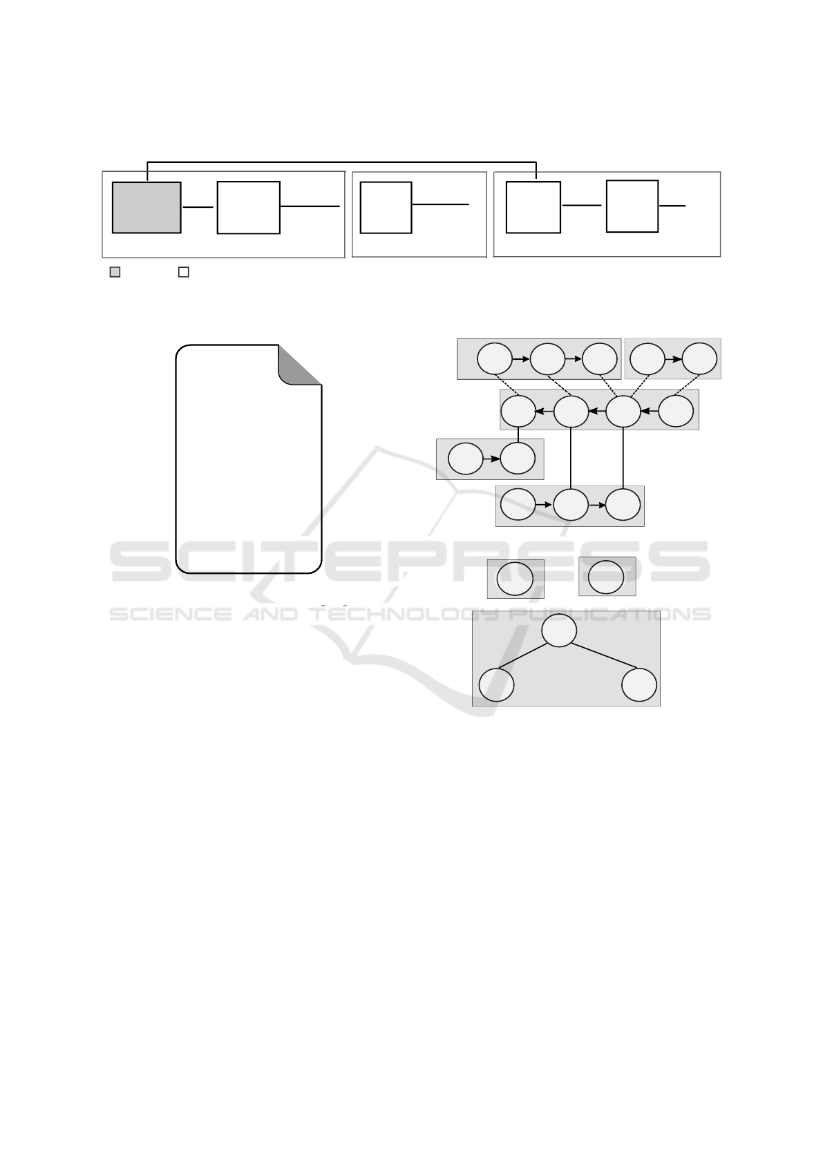
DSD system
description
Convert
DNA species
into graphs
Graph
Processor
Generate
PySB
model
PySB
BNGL
Simulator
simulation
results
DNA
species
--Strand graph
--Bond graph
--Species list
--DSD network
design.py
--DNA species count/concentration
--kinetics of DSD reactions
Domain-level DSD to DNA species graphs
DSD network generation
BNGL-based simulation
manual
automated
Figure 3: The RuleDSD pipeline for modelling and simulation of domain-level DSD systems.
catalytic_dsd_input.txt
<2 3^ 4>
//
<4 5^>
//
<1 2!1>
<6 3^!2 4!3>
<5^* 4*!3 3^*!2 2*!1>
--
ss1 6500
ss2 5000
ss3 5000
--
RB 0.0003
RU 0.1126
R3 20
R4 20
Figure 4: Input to the RuleDSD pipeline: a domain-level
DSD model of the catalytic system (catalytic dsd input.txt).
of DNA strands. The set E consists of two subsets
representing existing edges and admissible edges, re-
spectively.
The Bond Graph, which is derived from the Strand
Graph, is an undirected graph that may also include
cycles. The set of vertices V in a BG consists of an
enumerated list of DNA strands in the SG. The edge
set E represents existing domain-domain bonds be-
tween any two DNA strands or within a DNA strand
(cycle), and therefore it is equivalent to the subset
of edges that represent existing bonds in its corre-
sponding SG. The BG of the catalytic DSD example
is shown in Figure 5b. The edges are shown with
the domain-domain bond information (m > n[i]) that
represents an existing bond between i
th
domain of
enumerated DNA strand #m and a domain in #n. A
symmetric bond information with respect to the other
DNA strand is given by n > m[j]. There can be multi-
ple edges between a set of vertices in a BG, for ex-
ample, the vertices 3 and 5 in the figure have two
edges represented by 3 > 5[3,2], and symmetrically,
5 > 3[2,3].
1
2
2*
3^*
4*
5^*
4
5^
2
3^
4
6
3^
4
1 2
3
4
5
(a)
4
5
3
1
2
4 > 3[2]
3 > 4[4]
5 > 3[2,3]
3 > 5[3,2]
(b)
Figure 5: Graph representations of the initial DNA species
of the catalytic DSD system example. (a) Strand Graph:
the five DNA strands, each inside a gray rectangular outline
represents a vertex of the graph. The vertices are enumer-
ated as 1 (red),2 (green), 3 (blue), 4 (black) and 5 (pink).
Each vertex is again a directed graph having number of ver-
tices equal to the number of domains in the corresponding
DNA strand. There are three types of connecting lines be-
tween the domains (shown inside circles): lines with arrow-
head represent domain-domain covalent bond within a DNA
strand; solid and dotted lines respectively represent exist-
ing and admissible bonds between the domains of the DNA
strands. (b) Bond Graph has five vertices each representing
a single DNA strand. The three vertices (black, blue and
pink), constituting a partially double-stranded DNA com-
plex, are connected while the other two (red and green)
that represent the single-stranded DNA species are discon-
nected.
RuleDSD: A Rule-based Modelling and Simulation Tool for DNA Strand Displacement Systems
163
3.2 Graph Processing and DSD
Network Generation
The central role of the RuleDSD pipeline is to gen-
erate the DSD network given the initial species, and
this role is played by the graph processor in Fig-
ure 3. There is an outer phase and an inner phase
in the graph processor to generate the DSD network:
generate new species and map species. In the outer
phase, the processor steps into a loop where it per-
forms checks on currently available species to obtain
all possible valid rules (as described in Section 2.1)
that can be applied to those species, resulting in new
species. The processor first derives a list of initial
species from the Strand Graph input, then executes
Algorithm 1.
Algorithm 1: Generate New Species.
Input: InitSL: List of Initial species
Output: SL: List of all possible species
1: function GENERATION(InitSL)
2: SL ← InitSL
3: visited[i] ← False for i = 0 to len(SL) − 1
4: cursor ← 0
5: while not visited[cursor] do
6: oldlen ← len(SL)
7: for i = cursor to oldlen − 1 do
8: SL ← SL +CheckMonoReaction(i)
9: visited[i] ← True
10: end for
11: comb ← combinations of old species
(whose index i in SL satisfies i < oldlen) and new
species (whose index i ≥ oldlen)
12: for j ∈ comb do
13: SL ← SL +CheckBiReaction( j)
14: end for
15: if oldlen 6= len(SL) then
16: cursor ← oldlen
17: else
18: cursor ← oldlen − 1
19: end if
20: newlen ← len(SL)
21: for i = oldlen to newlen − 1 do
22: visited ← visited + False
23: end for
24: end while
25: return SL
26: end function
There are two types of checks on species:
CheckMonoReaction(), which checks possible
monomolecular reactions (i.e., RB, RU, R3 and R4),
and CheckBiReaction(), which checks possible
bimolecular reactions (i.e., RB). These functions
convert the input species in text representation to its
SG, perform the checks on its BG to speed up the
calculations, and translate the results from BG to text
using SG.
The inner phase map species happens within both
checks above. Note that a species generated at a later
point might coincide with a species that has occurred
at an earlier point. Therefore, a mapping scheme that
creates a relation between an SG and its unique rep-
resentation (id) must be addressed. In this paper, we
use the unique canonical form of an SG as the id of
a particular species. Such canonical form can be de-
rived by using an alphabetic sort and a Breadth-first
search (BFS) on the SG. When the outer phase ter-
minates, the graph processor has information on the
entire list of DNA species and chemical reaction net-
work, as shown in Table 1 and Figure 6, respectively,
for our representative example of catalytic DSD sys-
tem.
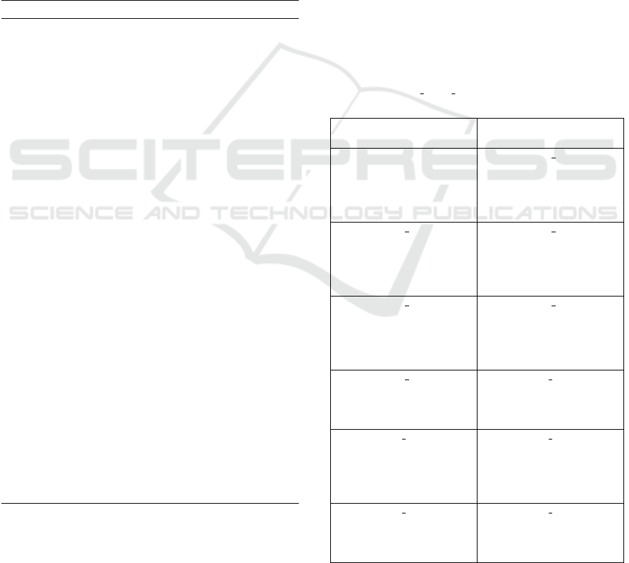
Table 1: The list of DNA species representing state-space
of the catalytic DSD system. Three species (ss1, ss2, and
ss3) are the initial species of the DSD system, and the other
eleven species (sp 4 - sp 14) are automatically generated by
RuleDSD.
ss1 ss2
< 2 3ˆ 4 > < 4 5ˆ>
ss3 sp 4
<1 2!1 > <4 5ˆ!1>
< 5ˆ
∗
4
∗
!2 3ˆ
∗
!3 2
∗
!1> <5ˆ
∗
!1 4
∗
!2 3ˆ
∗
!3 2
∗
!4 >
<6 3ˆ!3 4!2 > <6 3ˆ!3 4!2>
<1 2!4 >
sp 5 sp 6
<4!1 5ˆ!2 > < 4!1 5ˆ!2>
<5ˆ
∗
!2 4
∗
!1 3ˆ
∗
!3 2
∗
!4 > <5ˆ
∗
!2 4
∗
!1 3ˆ
∗
2
∗
!3 >
< 6 3ˆ!3 4> <1 2!3 >
< 1 2!4>
sp 7 sp 8
<6 3ˆ 4 > <2 3ˆ!1 4 >
<5ˆ
∗
!2 4
∗
!3 3ˆ
∗
!1 2
∗
!4 >
<4!3 5ˆ!2 >
<1 2!4 >
sp 9 sp 10
<2!1 3ˆ!2 4 > < 1 2>
< 5ˆ
∗
!3 4
∗
!4 3ˆ
∗
!2 2
∗
!1>
< 4!4 5ˆ!3>
sp 11 sp 12
<2 3ˆ!1 4!2 > <2!1 3ˆ!2 4!3 >
< 5ˆ
∗
!3 4
∗
!2 3ˆ
∗
!1 2
∗
!4> <5ˆ
∗
!4 4
∗
!3 3ˆ
∗
!2 2
∗
!1 >
<4 5ˆ!3 > <4 5ˆ!4 >
< 1 2!4>
sp 13 sp 14
< 2 3ˆ!1 4!2> <2!1 3ˆ!2 4!3 >
<5ˆ
∗
4
∗
!2 3ˆ
∗
!1 2
∗
!3 > <5ˆ
∗
4
∗
!3 3ˆ
∗
!2 2
∗
!1 >
< 1 2!3>
BIOINFORMATICS 2020 - 11th International Conference on Bioinformatics Models, Methods and Algorithms
164
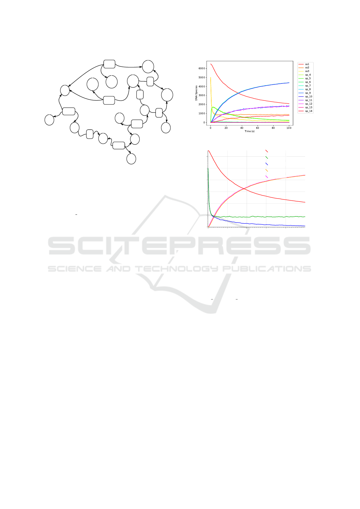
ss1
ss2
ss3
sp_4
sp_5
sp_6
sp_7
sp_8
sp_9
sp_10
sp_14
sp_11
sp_13
sp_12
RU|RB
R3
RB|RU
RU|RB
R3
R3
R3
RU|RB
RU|RB
Figure 6: The RuleDSD generated chemical reaction net-
work of our representative example of catalytic DSD sys-
tem. DNA species and reactions between them have circular
and rectangular outlines, respectively. Reaction transitions
between DNA species are shown in curved lines, where an
arrowhead marks the direction of the reaction transition.
For example, ss2 and ss3 react (shown by reaction rate, RB)
to produce sp 4, and this is a reversible reaction (reverse
reaction is shown by rate, RU).
4 RESULTS AND ANALYSIS
In this section, we present simulation results of
two DSD systems that have been modelled using
RuleDSD. We compare the results to the simulations
based on Visual DSD (Lakin et al., 2011). While the
deterministic simulations from both the tools are iden-
tical, stochastic simulations have some stochastically
indistinguishable variance.
4.1 Example 1
As a first example, we demonstrate a RuleDSD-based
simulation of the catalytic DSD system illustrated in
Section 3, Figure 2. The RuleDSD-generated full list
of DNA species of the catalytic DSD system is pre-
sented in Table 1. Note that the species are named
differently in the hand-derived reaction network (Fig-
ure 2) and the automatically generated RuleDSD list.
Figure 7 displays time-course plots of data from
a stochastic simulation of our catalytic DSD system
using RuleDSD and Visual DSD. The RuleDSD in-
put for this simulation is as in Figure 4, where ini-
tial DNA species, ss1, ss2, and ss3 are initialised with
population counts of 6500, 5000, and 5000, respec-
tively. The same simulation settings were also used
for the Visual DSD simulation.
While the dynamics of all DNA species gener-
(a)
DNA Species
0
1000
2000
3000
4000
5000
6000
0 20 40 60 80
Time (s)
ss1
ss2
ss3
sp1
sp2
(b)
Figure 7: Time-course data from stochastic simulations of
the catalytic DSD system using RuleDSD (a), and Visual
DSD (b).
ated by graph processing are plotted in the RuleDSD
simulation, only the initial, signal and output species
are plotted in the Visual DSD version. Note that the
species sp 10 and sp 7 in Figure 7a are identical to the
species sp1 and sp2 in Figure 7b, respectively. The
time-course data from the two stochastic simulations
reveal statistically equivalent simulation trajectories.
4.2 Example 2
As a second example, we present RuleDSD-based
simulation results of a DSD system consisting of
surface-tethered DNA complexes whose displace-
ment process involves both three-way and four-way
branch migration reactions (Qian and Winfree, 2014).
The initial DNA complexes, main reactions and inter-
mediate DNA complexes are shown in Figure 8.
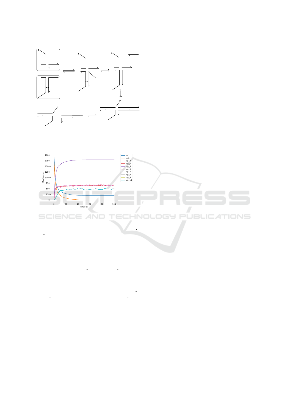
Time-course data from the stochastic simulation
of surface-tethered DSD system using RuleDSD is
shown in Figure 9. The two initial DNA species,
ss1 (blue) and ss2 (orange), undergo toehold binding,
as shown by a swift decrease in their respective ini-
tial populations, and produce an unstable intermedi-
RuleDSD: A Rule-based Modelling and Simulation Tool for DNA Strand Displacement Systems
165
L
T2^
T2^*
X*
X
T1^
A
A
A*
T1^*
X
X*
R
A
A*
T1^*
X
X*
R
L
T2^
T2^*
X*
X
T1^
A
A
A*
T1^*
X
X*
R
L
T2^
T2^*
X*
X
T1^
A
A*
T1^*
X
X*
R
L
T2^
T2^*
T1^
A
A*
T1^*
X
X*
R
L
T2^
T2^*
T1^
A
RB
UR
R3
R4
RB
UR
Figure 8: A surface-tethered DSD System involving both
3-way and 4-way branch migration reactions. Initial DNA
complexes are highlighted with outlines.
Figure 9: Stochastic simulation of a DSD system involv-
ing both three-way and four-way branch migrations. The
initial species, ss1 and ss2, have starting species counts of
2000 and 1800, respectively. Eight new DNA species (sp 3
– sp 10) were generated by the RuleDSD tool.
ate DNA complex, sp 3 (green that is covered by sp 6
(light green)).
The unstable DNA species, sp 3, undergoes a 3-
way branch migration that produces a sharp rise in the
populations of species sp 4 (red) and sp 5 (purple).
The DNA species sp 5 is another transitory DNA
structure that further reconfigures via a 4-way branch
migration producing sp 7 (pink), which further under-
goes a toehold dissociation to produce species sp 8
and sp 10. The dynamics of DNA species sp 4 and
sp 7 enter into a state of stochastic equilibrium due
to an effective reversible process that drives the tran-
sition back and forth between the two species. We
also simulated this DSD system using Visual DSD
and found identical time-course data, also reported
in (Petersen et al., 2016, Figure 7).
5 CONCLUSION AND FUTURE
WORK
In the context of domain-level DSD system mod-
elling, we have used a rule-based modelling approach
to represent DNA structures, converted them into
canonical graph representations, and applied rules
from the DSD reaction toolbox to generate a reaction
network that is simulated using the BNGL simulator
in the PySB framework. The RuleDSD pipeline is
publicly available for download as a Python package
at DSDPy.
We have studied several DSD systems using
RuleDSD and compared the results, such as the gener-
ated reaction networks and dynamics with the simula-
tions from Visual DSD. Due to space constraints only
two examples are reported here in Section 4; others
are available online at DSDPy. Both deterministic and
stochastic simulations of the studied systems show
compliance with Visual DSD (Lakin et al., 2011) sim-
ulations.
The RuleDSD implementation currently assumes
that there is more than one copy of each of the initial
DNA species in a given DSD system, thus the reac-
tion networks often grow very large or even infinite,
as both the generated DNA species and initial DNA
species can react to produce larger DNA structures.
However, the user can set a threshold value to limit the
size of the generated reaction networks in such cases
to prevent infinite growth. We aim to further develop
the RuleDSD tool to incorporate network-free simu-
lation methods, where species are generated by graph
processing only on demand, so that the entire network
does not need to be generated beforehand and hence
also DSD systems with very large state-spaces can be
modelled.
RuleDSD currently implements four basic types
of DSD reactions with generic kinetic rates. Al-
though a variety of DSD systems can quantitatively
be modelled using these generic reaction rates, we
need more types of reactions and variants of kinetic
rates to be included for qualitative analysis and accu-
rate modelling, respectively. For example, modelling
localised reactions (Bui et al., 2017), hairpin-based
reactions (Yin et al., 2008), and tethered DSD sys-
tems (Lakin et al., 2014) need specific kinetic rates to
be defined. Another feature currently lacking in the
RuleDSD that we are working on is a graphical user
interface for the visualization of DNA species and re-
action networks that are presently produced only in
text format.
BIOINFORMATICS 2020 - 11th International Conference on Bioinformatics Models, Methods and Algorithms
166

REFERENCES
Berleant, J., Berlind, C., Badelt, S., Dannenberg, F.,
Schaeffer, J., and Winfree, E. (2018). Automated
sequence-level analysis of kinetics and thermody-
namics for domain-level DNA strand-displacement
systems. Journal of the Royal Society Interface,
15(149):20180107.
Bui, H., Miao, V., Garg, S., Mokhtar, R., Song, T., and Reif,
J. (2017). Design and analysis of localized DNA hy-
bridization chain reactions. Small, 13(12):1602983.
Cardelli, L. (2013). Two-domain DNA strand displace-
ment. Mathematical Structures in Computer Science,
23(2):247–271.
Chen, Y.-J., Dalchau, N., Srinivas, N., Phillips, A., Cardelli,
L., Soloveichik, D., and Seelig, G. (2013). Pro-
grammable chemical controllers made from DNA.
Nature nanotechnology, 8(10):755.
Chylek, L. A., Harris, L. A., Tung, C.-S., Faeder, J. R.,
Lopez, C. F., and Hlavacek, W. S. (2014). Rule-
based modeling: a computational approach for study-
ing biomolecular site dynamics in cell signaling sys-
tems. Wiley Interdisciplinary Reviews: Systems Biol-
ogy and Medicine, 6(1):13–36.
Danos, V., Feret, J., Fontana, W., and Krivine, J. (2007).
Scalable simulation of cellular signaling networks. In
Asian Symposium on Programming Languages and
Systems, pages 139–157. Springer.
Danos, V. and Laneve, C. (2004). Formal molecular biol-
ogy. Theoretical Computer Science, 325(1):69–110.
Dirks, R. M., Lin, M., Winfree, E., and Pierce, N. A. (2004).
Paradigms for computational nucleic acid design. Nu-
cleic acids research, 32(4):1392–1403.
Faeder, J. R., Blinov, M. L., and Hlavacek, W. S. (2009).
Rule-based modeling of biochemical systems with
bionetgen. In Systems biology, pages 113–167.
Springer.
Gillespie, D. T. (2007). Stochastic simulation of chemical
kinetics. Annu. Rev. Phys. Chem., 58:35–55.
Grun, C., Sarma, K., Wolfe, B., Shin, S. W., and Winfree,
E. (2015a). A domain-level DNA strand displace-
ment reaction enumerator allowing arbitrary non-
pseudoknotted secondary structures. arXiv preprint
arXiv:1505.03738.
Grun, C., Werfel, J., Zhang, D. Y., and Yin, P. (2015b).
Dynamic workbench: an integrated development en-
vironment for dynamic DNA nanotechnology. Jour-
nal of the Royal Society Interface, 12(111):20150580.
Kawamata, I., Tanaka, F., and Hagiya, M. (2011). Abstrac-
tion of DNA graph structures for efficient enumera-
tion and simulation. In International Conference on
Parallel and Distributed Processing Techniques and
Applications, pages 800–806.
Kotani, S. and Hughes, W. L. (2017). Multi-arm junctions
for dynamic DNA nanotechnology. Journal of the
American Chemical Society, 139(18):6363–6368.
Lakin, M. R., Petersen, R., Gray, K. E., and Phillips, A.
(2014). Abstract modelling of tethered DNA circuits.
In International Workshop on DNA-Based Computers,
pages 132–147. Springer.
Lakin, M. R., Youssef, S., Polo, F., Emmott, S., and Phillips,
A. (2011). Visual DSD: a design and analysis tool for
DNA strand displacement systems. Bioinformatics,
27(22):3211–3213.
Lopez, C. F., Muhlich, J. L., Bachman, J. A., and Sorger,
P. K. (2013). Programming biological models in
python using pysb. Molecular systems biology, 9(1).
Panyutin, I. G. and Hsieh, P. (1994). The kinetics of spon-
taneous DNA branch migration. Proceedings of the
National Academy of Sciences, 91(6):2021–2025.
Petersen, R. L., Lakin, M. R., and Phillips, A. (2016). A
strand graph semantics for DNA-based computation.
Theoretical computer science, 632:43–73.
Phillips, A. and Cardelli, L. (2009). A programming lan-
guage for composable DNA circuits. Journal of the
Royal Society Interface, 6(suppl 4):S419–S436.
Qian, L. and Winfree, E. (2011). Scaling up digital circuit
computation with DNA strand displacement cascades.
Science, 332(6034):1196–1201.
Qian, L. and Winfree, E. (2014). Parallel and scalable com-
putation and spatial dynamics with DNA-based chem-
ical reaction networks on a surface. In International
Workshop on DNA-Based Computers, pages 114–131.
Springer.
Seelig, G., Soloveichik, D., Zhang, D. Y., and Winfree, E.
(2006). Enzyme-free nucleic acid logic circuits. sci-
ence, 314(5805):1585–1588.
Shin, J.-S. and Pierce, N. A. (2004). A synthetic DNA
walker for molecular transport. Journal of the Ameri-
can Chemical Society, 126(35):10834–10835.
Sneddon, M. W., Faeder, J. R., and Emonet, T. (2011). Ef-
ficient modeling, simulation and coarse-graining of
biological complexity with nfsim. Nature methods,
8(2):177.
Soloveichik, D., Seelig, G., and Winfree, E. (2010).
DNA as a universal substrate for chemical kinetics.
Proceedings of the National Academy of Sciences,
107(12):5393–5398.
Spaccasassi, C., Lakin, M. R., and Phillips, A. (2018). A
logic programming language for computational nu-
cleic acid devices. ACS synthetic biology.
Srinivas, N., Parkin, J., Seelig, G., Winfree, E., and Solove-
ichik, D. (2017). Enzyme-free nucleic acid dynamical
systems. Science, 358(6369):eaal2052.
Yin, P., Choi, H. M., Calvert, C. R., and Pierce, N. A.
(2008). Programming biomolecular self-assembly
pathways. Nature, 451(7176):318.
Yurke, B. and Mills, A. P. (2003). Using DNA to power
nanostructures. Genetic Programming and Evolvable
Machines, 4(2):111–122.
Yurke, B., Turberfield, A. J., Mills Jr, A. P., Simmel, F. C.,
and Neumann, J. L. (2000). A DNA-fuelled molecular
machine made of DNA. Nature, 406(6796):605.
Zhang, D. Y. and Seelig, G. (2011). Dynamic DNA nan-
otechnology using strand-displacement reactions. Na-
ture chemistry, 3(2):103.
Zhang, D. Y., Turberfield, A. J., Yurke, B., and Winfree, E.
(2007). Engineering entropy-driven reactions and net-
works catalyzed by DNA. Science, 318(5853):1121–
1125.
RuleDSD: A Rule-based Modelling and Simulation Tool for DNA Strand Displacement Systems
167
