
Configurable External Defibrillator Devoted
to Education and Clinical Trials
Victor D. N. Santos
1,2 a
, J. Cândido Santos
1b
and N. M. Fonseca Ferreira
1,3 c
1
Coimbra Polytechnic – ISEC, Rua Pedro Nunes - Quinta da Nora, 3030-199 Coimbra, Portugal
2
INESC Coimbra, Rua Sílvio Lima, pólo II DEEC, 3030-790 Coimbra, Portugal
3
GECAD, Polytechnic Institute of Porto (IPP), 4200-465 Porto, Portugal
Keywords: External Defibrillator, Defibrillation Waveforms, Rectilinear Biphasic, Biphasic Truncated Exponential.
Abstract: External defibrillators are recognized effective to revert ventricular fibrillation and pulseless ventricular
tachycardia. This paper presents a new settable defibrillator, designed to assess the effectiveness of the
following defibrillation waveforms during clinical trials: monophasic damped sinusoidal (MDS); biphasic
truncated exponential (BTE) and rectilinear biphasic waveform (RBW). The device flexibility allows the
setting of the defibrillation waveforms most relevant parameters, namely energy and pulses duration. The
device usage is also relevant in biomedical engineer and medical staff education and training programs.
1 INTRODUCTION
Cardiovascular diseases take a leading role in the
morbidity and mortality of the Western countries
populations. International experience shows that the
use of an automated external defibrillator (AED),
outside the hospitals, by non-medical personnel,
significantly increases the probability of survival of
the victims. However, only the existence of an
efficient survival chain, makes AED an effective way
to improve survival after cardiorespiratory arrest.
AED is a device capable of automatically
identifying defibrillating heart rhythms, alerting to
safety conditions, and complete the steps of the
approved algorithm on cardiopulmonary resuscitation
to produce electric discharges automatically or under
the command of an external operator, according to
predefined energy values. It also records the data
from the electrocardiographic to support later
auditing.
Patient’s defibrillation is obtained by the delivery
of a suitable electrical current through their
myocardium, able to depolarize a critical myocardial
mass and thereby re-establish a coordinated electrical
activity that leads to an organized sinus rhythm and
spontaneous circulation.
a
https://orcid.org/0000-0002-5441-4394
b
https://orcid.org/0000-0003-0494-4335
c
https://orcid.org/0000-0002-2204-6339
Several studies have demonstrated that biphasic
waveform shocks are superior to monophasic shocks
to revert cardiac arrest caused by ventricular
fibrillation (Keener et all., 1999; Zhang et all., 2003).
This arises from the fact that in biphasic waveforms
the current flows in a predefined direction during a
time period and thereafter reverses the current flow to
the opposite direction for the remaining pulse
duration. These type of pulses improve defibrillation
efficiency by diminishing the defibrillation threshold
value and the underling associated hazards.
Further studies (Zhang et all., 2003), performed in
animal’s, indicate that the benefits of biphasic
waveform could be further enhanced by using of a
triphasic waveform composed of three pulses with
reversed polarities i.e. the polarity of the second pulse
is opposite to that used on the first and third pulses.
Recent published studies (Mittal et all., 1999),
patents (Dascoli et all., 2017) and commercial devices
(Zoll, 2018) point to rectilinear biphasic waveform
(RBW). Those devices deliver an approximately
constant current during the first phase of a pulse,
independent of the patient’s transthoracic impedance
(TTI). The optimal current for ventricular
defibrillation appears to be 30 to 40 A (Tavakoli et
all., 2017). In the pulse second phase the current
142
Santos, V., Santos, J. and Ferreira, N.
Configurable External Defibrillator Devoted to Education and Clinical Trials.
DOI: 10.5220/0008977701420148
In Proceedings of the 13th International Joint Conference on Biomedical Engineering Systems and Technologies (BIOSTEC 2020) - Volume 1: BIODEVICES, pages 142-148
ISBN: 978-989-758-398-8; ISSN: 2184-4305
Copyright
c
2022 by SCITEPRESS – Science and Technology Publications, Lda. All rights reserved

decays according with a first order RC circuit
transient, negative exponential pulse, being its
polarity opposite regarding the first one.
This paper presents a novel programmable
defibrillator device devoted to either clinical studies
and educational purposes. The assessment of the
therapeutic efficiency of different defibrillation
waveforms is only possible by means of the pulses
characteristics definition: waveform, amplitude,
energy and individual pulses duration time periods.
The implemented device comprises a micro
controlled electronic unit connected with a Labview
application that performs the pulse configuration and
the acquired ECG signals processing. The device
allows the implementation of different defibrillation
waveforms. The monophasic damped sinusoidal
(MDS) is obtained from the Lown circuit being the
biphasic truncated exponential (BTE) and the
triphasic waveforms implemented using a H bridge.
The current based defibrillation waveform includes a
set of low value resistances that are electronically
bypassed as the capacitor voltage drops, keeping the
current value almost constant in the initial pulse
phase. Moreover, the implemented defibrillator has
an ECG signal acquisition unit, able to identify
defibrillable heart rhythms. The acquired signal is
later processed to synchronize the location of the
defibrillation pulse with respect to the QRS complex.
The paper is organized as follows. Section 2,
describes and analyses the waveforms typically used
on defibrillators, the underlying theoretical concepts
and the employed electronic circuits. Moreover, the
results retrieved from each particular circuits are also
presented. Section 3, presents the design and
implementation issues of the defibrillator. Section 4
covers the implementation and tests on the novel
defibrillator in the biomedical engineers courses
education in the Institute Polytechnic of Coimbra
(IPC). Finally, Section 5 presents the main
conclusions and future work.
2 DEFIBRILLATION
WAVEF OR MS
The developed defibrillator is capable to generate
different defibrillation pulses: MDS, BTE or RBW by
selecting one of the implemented circuits, explained
in detail in the following sections. The circuit analysis
is added to explain the waveform generation process
and its parameterization.
2.1 Origin and Evolution of the
Defibrillators
Defibrillation was first demonstrated in 1899 by
Prevost and Batelli. They discovered that small
electric shocks could induce ventricular fibrillation in
dogs, and that larger charges would reverse that
condition. The defibrillator was invented in 1932 by
Dr. William B. Kouwenhoven and its first use on a
human was conducted in 1947 by Claude Beck
(Akselrod et all., 2009; Tavakoli et all., 2017).
Until the early 1950s, defibrillation of the heart
was possible only when the chest cavity was open
during surgery. The technique used an alternating
current (AC) delivered to the sides of the exposed
heart by paddle electrodes. During his PhD work
Gurvich discovered that direct current (DC) shocks
were significantly more efficient and less damaging
than AC in defibrillation.
In 1959 Bernard Lown began to investigate the
use of monophasic DC shocks resultant from the
discharge of capacitors over patients. The designed
method assumes that a capacitor or a bank of
capacitors is kept at a high voltage (Akselrod et all.,
2009). The energy stored in the capacitors is then
delivered to the patient’s chest through an additional
inductor, in order to produce a classical MDS
waveform of finite duration. This approach follows
previous work performed in human patients reported
by both Gurvich and Peleska (Akselrod et all., 2009).
The Lown waveform was the standard for
defibrillation until the late 1980s when research
showed that a BTE waveform with both positive and
negative pulses could provide equal or even better
results requiring lower energy levels, thereby
increasing patient safety and reducing burden on the
power supply system and batteries (Akselrod et all.,
2009, Tavakoli et all., 2017).
2.2 Lown Defibrillator
The Lown defibrillator is based on the RLC series
circuit depicted in Fig. 1.
Figure 1: Lown defibrillator circuit. (Irwin, 2015).
Configurable External Defibrillator Devoted to Education and Clinical Trials
143
The analysis of the circuit assumes that the
capacitor was previously charged at a high voltage
level, being then connected in series to an inductor
and resistor at instant t = 0 s. The defibrillation pulse
applied to the patient (resistor) is the solution of the
second-order differential equation obtained by the
application of KVL around the circuit loop.
0
2
2
LC
ti
dt
tdi
L
R
dt
tid
(1)
The solution of (1) must be a function whose first
and second derivatives have the same form as the
original function in order to the left side of the
equation becoming zero (Irwin, 2015). The solution
st
eKti
is then replaced in (1) resulting in
0
1
2
LC
s
L
R
seK
st
(2)
Since
st
eK
is the assumed solution, the
expression in parentheses will have to be zero. That
quadratic equation is known as the characteristic
equation of the second-order differential equation (1),
since the roots of that equation dictate the behaviour
of
ti . Using the quadratic formula, two roots of (2)
can be found:
2
0
2
2
2
0
2
1
;
ss
(3)
assuming that
L
R
2
and
LC
1
0
(4)
The roots s
1
and s
2
are associated with the natural
response of the circuit; ω
0
is known as the undamped
natural frequency, expressed in radians per second
(rad/s); and α is the damping factor, expressed in
nepers per second.
If α > ω
0
both roots s
1
and s
2
are negative and real
(overdamped case) (Alexander, 2012). Thus, the
current decays and approaches zero as t increases.
tt
d
C
dd
ee
L
V
ti
2
(5)
with
2
0
2
d
.
If α < ω
0
the roots s
1
and s
2
are complex conjugate
being the electric current given by (underdamped
case) (Irwin, 2015; Alexander, 2012)
te
L
V
ti
d
t
d
C
sin
(6)
with
22
0
d
. In (5) and (6) the constant
factor was obtained from two initial conditions: the
initial value of the current and its first derivative.
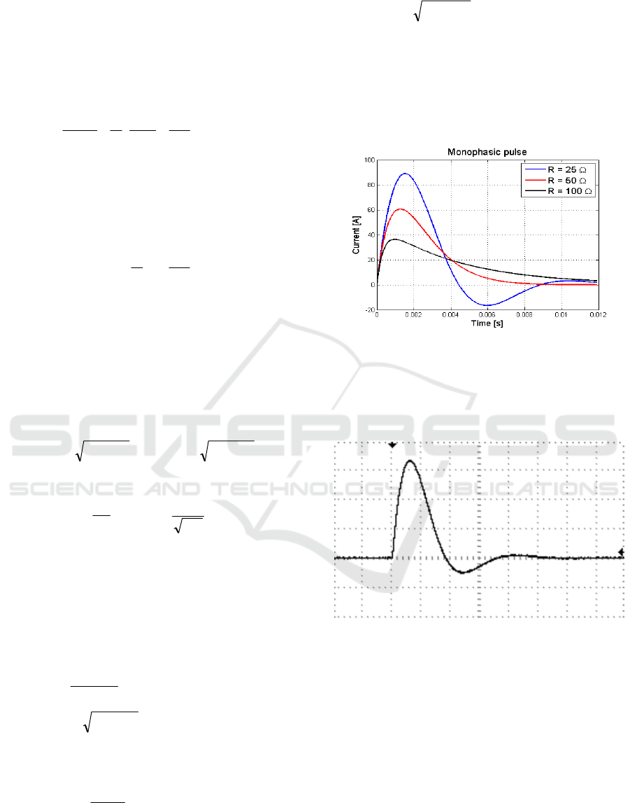
Fig. 2 presents the simulated MDS waveforms for
patients with resistance values equal to 25 Ω; 50 Ω
and 150 Ω. The results were obtained assuming the
usage of a 47 µF capacitor and a 33 mH inductor and
an initial voltage level in the capacitor, of 4.2 kV.
Figure 2: Lown waveform in function of the impedance.
Fig. 3 shows the MDS waveform acquired in the
lab using the above components and a R = 25 Ω. In
this case the system is underdamped with α = 378.78,
ω
0
= 802.96 rad/s and ω
d
= 708 rad/s.
Figure 3: Lown waveform in function of the impedance.
In Fig. 3 the signal was acquired setting the
TIME/DIV control of the oscilloscope to 1 ms/DIV.
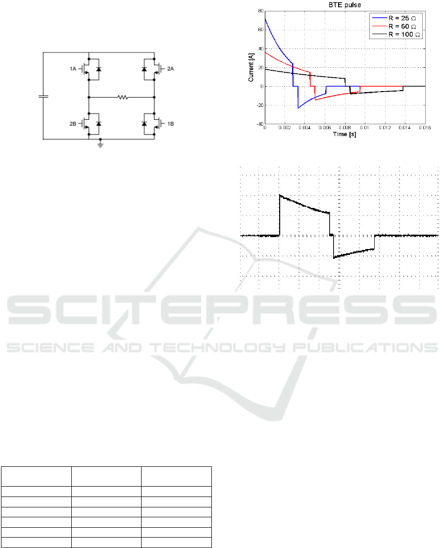
2.3 BTE Defibrillators
In order to generate a BTE waveform defibrillation
pulses a new circuit, represented in Fig. 4 is needed.
It uses a high-voltage capacitor and a H bridge. The
capacitor is charged with a high DC voltage value that
meets the selected energy value to be applied. After
charging the capacitor with the desired voltage value,
the energy stored in it is then delivered to the patient
as a defibrillation pulse. The H-bridge is used to
BIODEVICES 2020 - 13th International Conference on Biomedical Electronics and Devices
144
control transfer of energy from the capacitor to the
patient. It includes four electronic switches (placed on
the H-bridge legs), that are used to define the polarity
applied to the load (patient).
Figure 4: BTE waveform defibrillator circuit.
During the first phase of the waveform, the H
bridge connects the capacitors’ two terminals with the
defibrillator paddles placed on the patient. At the end
of the pulse first phase that connection is opened and
the terminals of the capacitor are switched to connect
in the reverse polarity to the mentioned paddles. It is
advisable to have a small guard time interval between
phases in order to avoid the simultaneous connection
of the switch in the same side of the H-bridge
(Sullivan, 1997).
The didactic version of the configurable external
defibrillator device uses the TB6612FNG H bridge to
control de discharge of the capacitor over the load
(patient). This driver IC is devoted to perform the
control of up two DC motors. The mentioned device
requires three input signals, IN1, IN2 and STBY to
select the four modes of operation corresponding to
the normal operation CW, in one direction, and CCW;
in the opposite direction; the high impedance mode
and the short brake mode.
The mentioned control signals are obtained from
a ATmega328P microcontroller according with the
patient impedance value.
Table 1: BTE parameters for adults (Philips, 1997).
Load
resistance (Ω)
Phase II
duration (ms)
Phase II
duration (ms)
25 2.8 2.8
50 4.5 4.5
75 6.25 5.0
100 8.0 5.3
125 9.64 6.4
150 11.5 7.7
Fig. 5 depicts the simulated BTE waveform
delivered to patients with resistance values equal to
25 Ω; 50 Ω and 150 Ω. The presented results assume
a 100 µF capacitor and an initial voltage of 1.8 kV.
The pulse phases durations of the BTE waveform are
presented in table I.
Figure 5: BTE waveform in function of the impedance.
Figure 6: BTE waveform.
Fig. 6 shows the BTE waveform obtained in the
laboratory, from the developed device using the
following components C = 100 uF and R = 50 Ω and
the H-bridge. The signal was acquired setting the
TIME/DIV control of the oscilloscope to 1 ms/DIV.
2.4 Rectilinear Biphasic Waveform
Defibrillators
The RBW implementation is based on the circuit used
for the BTE waveforms. In order to achieve an
approximately constant current during the first pulse,
as the capacitor discharges across the patient chest, is
needed to decrease the circuit impedance accordingly.
The underlying idea of a RBW defibrillator
operation comprises the inclusion of several series-
connected resistors, in the current path, in series with
the patient impedance. Each one of those additional
resistors is connected in parallel with a shorting
switch controlled by a micro-controller providing an
extremely low resistance path to the current (Fig. 7).
The resistors should have different resistance values
to tune the current with a high accuracy to a nearly
constant value.
Configurable External Defibrillator Devoted to Education and Clinical Trials
145

Figure 7: RBW defibrillator circuit.
When the H-bridge switches, of opposite legs, are
closed, in the beginning of the pulse, all the resistor-
shorting switches are open, to force the current to
passes through each one of the mentioned added
resistors.
As the voltage in the capacitor decays, with a time
constant R·C, the additional resistors in series with
the patient are successively shorted out. Each time
that one of the resistors is bypassed, the current
increases instantaneously, taking into account that the
capacitor voltage remains the same, as the event
happens. Thus, it can be observed significant ripple,
in the positive phase of the RBW (Fig. 8), matching
the repeated activation of the resistor-shorting
switches. The ripple magnitude is larger at the end of
the rectilinear phase because the time constant value
is smaller at the end of the phase than at the
beginning.
At the end of the positive phase all the H-bridge
switches legs are open to ensure a safety guard time
period before invert the direction of the current flow.
The polarity of the waveform is reversed by closing
the H-bridge switches that were open in first positive
phase and vice versa.
Figure 8: RBW waveform in function of the impedance.
Fig. 8 shows the RBW obtained by simulation. In
the conducted simulations was assumed impedances
equals to 50 Ω; 75 Ω and 100 Ω. Moreover, it was
assumed the usage of a 100 µF capacitor, three 10 Ω
additional resistor’s and an initial voltage value of
2.3 kV.
The device that generates the RBW defibrillator is
based on the TB6612FNG H bridge and on the earlier
mentioned ATMEL microcontroller. However,
additional control signals must be generated in order
to manage each one of the bypass transistors. The
signals are defined to turn on each transistor at
particular time instants. The transistors sequence of
operation is always the same and starts with the
transistor connected to the ground and ends with the
transistor connected with the H bridge.
3 DEFIBRILLATION DESIGN
ISSUES
The implemented novel defibrillator, is expected to
be comparable to the existent commercial devices
including all its features, being also compliant with
international standards. The prototype consists of a
hardware part that implements the mentioned
waveforms and performs the conditioning and
acquisition of the patient’s ECG signals and the TTI
evaluation. The device includes a power supply unit,
a micro-controller unit, and several electronic
components. The power source can come either from
a battery or from the main supply using an electronic
rectifier.
As mentioned earlier the capacitor is the vital
element of the defibrillator, it stores a large amount
of energy in its electric field, then releases it on a
patient’s chest accordingly with the system
configuration and TTI value. The capacitor charging
circuit includes a series-resistor to limit the current
value and two electronic sensors to measure, in real
time basis, the absorbed /delivered current (Hall
effect sensor) to/from the capacitor and the voltage
value across its terminals.
A signal conditioning circuit was also
implemented, depicted in Fig. 9, in order to perform
the mentioned ECG signal acquisition. That circuit
employs the low cost AD620 instrumentation
amplifier and the LM358N operational amplifier, a
band pass filter and right leg reference circuit.
BIODEVICES 2020 - 13th International Conference on Biomedical Electronics and Devices
146
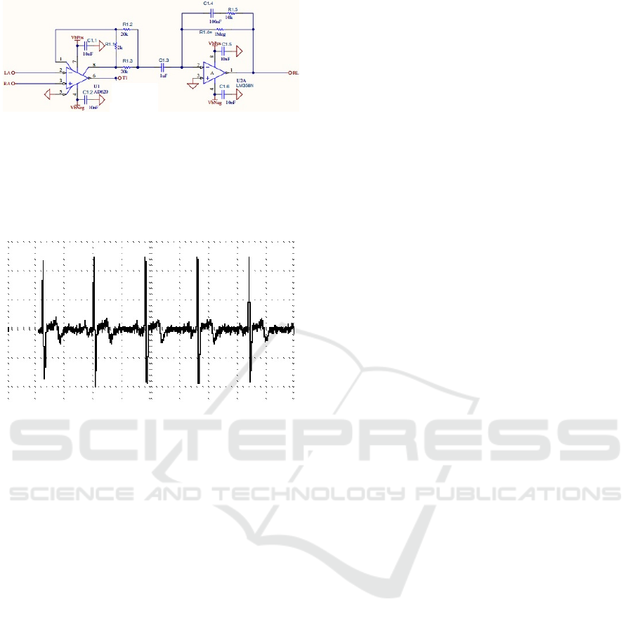
Figure 9: ECG signal conditioning circuit.
The amplified ECG signal is thereafter acquired
by a National Instruments low-cost, multifunction
DAQ. Fig. 10 presents the acquired ECG signal of a
healthy patient, in the test bed, using the conditioning
circuit of Fig 9.
Figure 10: Acquired ECG signal from a patient.
The described circuits are controlled by a software
component (LabView) which implements a state
machine underlying the operation of the external
defibrillator as well as all the signal processing
operations.
The procedures related with the defibrillator
capacitor are controlled by a state machine that ensure
the correct: charging state; charge maintenance,
discharge, safety discharge. The state machine also
controls other events that take place in a logical order
in order to avoid the occurrence of conditions that
compromise the device and/or the user safety.
The following features were implemented in the
software:
Defibrillator state machine;
Charging and discharging circuits monitoring;
ECG signal acquisition, filtering, processing
and representation;
QRS complex identification;
Patient impedance value assessment;
H bridge and control timing signals generation;
Data storage.
To avoid the hazard of ventricular fibrillation
resultant from the application of the DC pulse, the
discharge should be synchronized with the
electrocardiogram. The defibrillation pulse must be
applied during or immediately after the downward
slope of the R wave (Zoll, 2018). The synchronization
avoids the delivery of the shock during the T wave
that corresponds to a partially refractory vulnerable
period during which ventricular fibrillation could
occur in the presence of an external electric stimulus.
4 LIFE SUPPORT SYSTEMS
EDUCATION
The Coimbra Institute of Engineering (ISEC) is a
Portuguese higher education Polytechnic school,
integrated in the Coimbra Polytechnic Institute. Its
formative offer includes, among others, the
biomedical engineering and biomedical
instrumentation, first and second cycles whose
curricula have been designed accordingly to the
Bologna process.
The presented external defibrillator was designed
and implemented on the Life Support Systems (LSS)
curricular unit of the second semester of the
biomedical instrumentation master course. This unit
is relevant taken into account that in Portugal,
cardiovascular diseases are one of the most serious
health problems of the population (Santos, 2019).
This curricular unit aims to provide skills and
knowledge regarding the existent basic and advanced
life support equipment. Furthermore, it is intended
that students acquire fundamental knowledge, in the
electrical engineering area regarding the design,
implementation and maintenance of such equipment.
Additionally, R&D activities are encouraged on
students, which result on the proposal of new
approaches and circuits in compliance with the
international standards.
Students that successfully complete the unit
should be able to understand RC and RLC transients
in order to design Lown BTE and RBW
defibrillators’; to understand, pacemakers’ and AEDs
devices’ operation and functionalities. To understand
the underling theory and sensor technology needed to
obtain the vital signals monitoring and finally to
understand the operation principles of the most
common ventilators.
Configurable External Defibrillator Devoted to Education and Clinical Trials
147

5 CONCLUSIONS
This paper describes a novel defibrillator capable to
implement different defibrillation pulses, namely: the
MDS, BTE and RBW waveforms, using different
electrical and electronic components and circuits.
With respect to the Lown defibrillator is only
possible to define the energy delivered to the patient.
The generated MDS waveforms in the test bed, were
validated using the results obtained from simulation
of the RLC circuit under the same assumptions. The
defibrillator settings allow BTE and RBW waveforms
provision by means of the H bridge circuit usage. An
external micro-controller is responsible for the pulses
different phases timings accordingly with the
measured patient impedance value. The retrieved
laboratory results, from the defibrillator, were
compared and validated with the ones obtained by the
circuits simulation.
Additionally, more advanced features were also
employed and implemented in order to evaluate the
effectiveness of different defibrillation waveforms
and parameters during clinical trials.
Moreover, the design, implementation and test of
the developed configurable defibrillator in the LSS
curricular unit has engaged students on R&D
activities; promoted the academic success, the
students’ motivation facing a real practice problem
and the improvement of students’ skills teamwork,
communication and leadership.
ACKNOWLEDGEMENTS
This work has been supported by the Portuguese
Foundation for Science and Technology (FCT) under
project grant UID/MULTI/00308/2019.
REFERENCES
A.P. van Alem, Arrest 4: Out-of-hospital resuscitation with
automated external defribillators, University of
Amsterdam, UvA-DARE (Digital Academic
Repository), march 2004.
Akselrod H., Kroll M.W., Orlov M.V. “History of
Defibrillation”. In: Efimov I.R., Kroll M.W., Tchou P.J.
(eds), Bioelectric Therapy: Mechanisms and practical
implications. Springer, pp 15-40, 2009.
Charles Alexander, Matthew Sadiku, Fundamentals of
Electric Circuits: 5th edition, Prentice Hall, 2012.
Dascoli, M. et al. Zoll Medical Corporation, “Pediatric and
adult defibrillator,” U.S. Patent US10300293B2,
published Sep 7, 2017.
J. David Irwin, R. Mark Nelms, Basic engineering circuit
analysis. 11th edition Wiley, 2015.
J. P. Keener, T.J. Lewis, “The Biphasic Mystery: Why a
Biphasic Shock is More Effective than a Monophasic
Shock for Defibrillation,” Journal of Theoretical
Biology, vol. 200, 1, 1999. DOI:
10.1006/jtbi.1999.0972
Joseph L. Sullivan, Lawrence A. Borschowa, Richard C.
Nova, “H-bridge circuit for generating a high-energy
biphasic waveform in an external defibrillator”, U.S.
Patent US5824017A, issued march 5, 1997.
Mittal S, et. al., “Comparison of a novel rectilinear biphasic
waveform with a damped sine wave monophasic
waveform for transthoracic ventricular defibrillation,”
Journal of the American College of Cardiology, vol. 34,
5, 1999, DOI: 10.1016/S0735-1097(99)00363-0,
Philips HeartStart HS1 Defibrillators, Technical Reference
Manual, 2007.
Tavakoli Golpaygani, A et al. “A Study on Performance
and Safety Tests of Defibrillator Equipment” Journal of
biomedical physics & engineering, vol. 7, 4, pp. 397-
402. 1 Dec. 2017.
Victor D. N. Santos, J. Cândido Santos and Joaquim
Pereira; “Life Support Systems Education Based on
Project-Based Learning”, Proc. of the 3rd International
Conference on Engineering Applications, ICEA19,
Ponta Delgada, Portugal, July 8-11, 2019
Yi Zhang, Richard E Kerber, et al., “Triphasic waveforms
are superior to biphasic waveforms for transthoracic
defibrillation: Experimental studies,” Journal of the
American College of Cardiology, vol. 42, 3, 2003.
Zoll R Series Operator's Guide. Available in
https://www.zoll.com/
BIODEVICES 2020 - 13th International Conference on Biomedical Electronics and Devices
148
